EP0741378B1 - Dispositif pour afficher des illustrations, des textes et autres - Google Patents
Dispositif pour afficher des illustrations, des textes et autres Download PDFInfo
- Publication number
- EP0741378B1 EP0741378B1 EP96201009A EP96201009A EP0741378B1 EP 0741378 B1 EP0741378 B1 EP 0741378B1 EP 96201009 A EP96201009 A EP 96201009A EP 96201009 A EP96201009 A EP 96201009A EP 0741378 B1 EP0741378 B1 EP 0741378B1
- Authority
- EP
- European Patent Office
- Prior art keywords
- wheel
- shaped
- nose
- display means
- rotation
- Prior art date
- Legal status (The legal status is an assumption and is not a legal conclusion. Google has not performed a legal analysis and makes no representation as to the accuracy of the status listed.)
- Expired - Lifetime
Links
- 230000007423 decrease Effects 0.000 claims description 2
- 238000010276 construction Methods 0.000 description 4
Images


Classifications
-
- G—PHYSICS
- G09—EDUCATION; CRYPTOGRAPHY; DISPLAY; ADVERTISING; SEALS
- G09F—DISPLAYING; ADVERTISING; SIGNS; LABELS OR NAME-PLATES; SEALS
- G09F11/00—Indicating arrangements for variable information in which the complete information is permanently attached to a movable support which brings it to the display position
- G09F11/02—Indicating arrangements for variable information in which the complete information is permanently attached to a movable support which brings it to the display position the display elements being secured to rotating members, e.g. drums, spindles
- G09F11/025—Indicating arrangements for variable information in which the complete information is permanently attached to a movable support which brings it to the display position the display elements being secured to rotating members, e.g. drums, spindles the members being rotated simultaneously, each face of the member carrying a part of the sign
Definitions
- the invention relates to a device for displaying illustrations, texts or the like provided with a frame and with a plurality of display means which are rotatable about parallel axes of rotation, said display means comprising a few surfaces extending at least substantially parallel to said axes of rotation and including an angle with each other, said surfaces being provided with parts of the illustrations, texts or the like to be formed, whilst wheel-shaped driving means are disposed near ends of said display means, which wheel-shaped driving means can be rotated about their central axes extending transversely to the axes of rotation of the display means in order for said display means to be rotated, whereby said wheel-shaped means cooperate with pins secured to the ends of said display means, the pins are disposed in regularly spaced-apart relationship on a circle extending concentrically about the axis of rotation of the display means, whilst said wheel-shaped means is provided with a projecting nose, on either side of which passages for the pins are formed in said wheel-shaped means, all this in such a manner that
- a disadvantage of this known device is that the display means is freely rotatable about its axis if the pin of the wheel-shaped means is not coupled with the pins of the display means.
- the object of the invention is to provide a device whereby the display means are not freely rotatable.
- this object is accomplished in that the pins secured to the display means extend parallel to the axis of rotation of the respective display means, the projecting nose provided on the wheel-shaped means extends parallel to the axis of rotation of the respective wheel-shaped means, whereby two of the pins are each guided through one of said passages from one side of the wheel-shaped means to the other side of said wheel-shaped means.
- the wheel-shaped means prevent the display means from an undesired rotation.
- a device for displaying illustrations etc. is known from European Patent Application No. 0 539 308.
- Various illustrations, texts or the like can be displayed in succession with such a device by rotating the display means.
- three pins extending in radial direction with respect to the display means are secured to each display means.
- Said pins cooperate with a wheel-shaped means which is circumferentially provided with a helical groove in which said pins engage and through which said pins move in order to rotate the respective display means.
- the wheel-shaped means with a helical groove formed therein makes this a complicated and costly construction.
- the wheel-shaped means must furthermore be disposed beside the extension of the axis of rotation of the display means, which leads to a comparatively great width of the device, seen in a direction perpendicularly to the plane through the axes of rotation of the wheel-shaped means.
- One embodiment of the device according to the invention is characterized in that said wheel-shaped means is provided with two parallel flanges positioned as seen in axial direction on the same side of said nose, said flanges near said nose being provided with passages for guiding one of said pins from a side facing said nose of the flange located near said nose to a side facing away from said nose of the other flange, and vice versa.
- the nose is in engagement with said pins only over a particular part of a revolution of the wheel-shaped means.
- the flanges provide an accurate guiding and positioning of the pins positioned between the flanges.
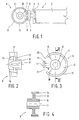
- Figure 1 is schematically shows one end of a display means with pins secured thereto and a wheel-shaped means cooperating with said pins.
- Figure 2 is a larger-scale view of a wheel-shaped means.
- Figure 3 is a side view of Figure 2.
- Figure 4 is a sectional view of Figure 3, along line IV-IV in Figure 3.
- Figures 5a-5g schematically show relative positions, seen from the central axis of the wheel-shaped means in the direction of the outer circumference of the wheel-shaped means, which pins secured to a display means and the wheel-shaped means take up with respect to each other when the wheel-shaped means is rotated in order to effect a rotation of the display means.
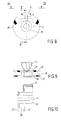
- Figure 6 is a perspective view of a second embodiment of a device according to the invention.
- Figure 7 is a perspective view of the device shown in Figure 6, in another position thereof.
- Figure 8 is a larger-scale view of a wheel-shaped means according to the invention shown in Figure 6.
- Figure 9 is a side view of Figure 8.
- Figure 10 is a sectional view of Figure 8, along line X-X in Figure 8.
- Figures 11A-G schematically show relative positions, seen from the central axis of the wheel-shaped means in the direction of the outer circumference of the wheel-shaped means, which pins secured to a display means and the wheel-shaped means take up with respect to each other when the wheel-shaped means is rotated in order to effect a rotation of the display means.
- Figure 1 shows one end of a display means 1, which is provided with three surfaces 2 including an angle with each other, which surfaces 2 form an equilateral triangle, seen in sectional view of the display means 1.
- a plurality of such display means are arranged in parallel relationship, and are journalled in supports 3 in such manner as to be rotatable about axes of rotation extending in the longitudinal direction of the display means, said supports 3 forming part of a frame of a device for displaying illustrations of which display means 1 forms part.
- the surfaces 2 are thereby intended for being provided with illustrations, texts or the like.
- a shaft 4 is mounted on one end of display means 1, the central axis of said shaft coincides with the axis of rotation of display means 1.
- a disc 5 extending perpendicularly to shaft 4 is mounted on the end of said shaft 4.
- Three pins 6 - 8 are mounted on said disc, on the side facing away from shaft 4, said pins extending parallel to shaft 4 and thus parallel to the axis of rotation of display means 1.
- the pins are thereby arranged at regular angular distances apart on a circle extending concentrically about the axis of rotation of display means 1.
- Said pins co-operate with a wheel-shaped means 9 illustrated in more detail in Figures 1 - 4.
- Said wheel-shaped means comprises a hub 10, in which a (preferably unround) hole 11 is formed, said hole being hexagonal in the illustrated embodiment.
- a plate-shaped disc 12 extending perpendicularly to the central axis of hole 11 is mounted on said hub, said disc extending through approximately 270° about the central axis of hole 11.
- Mounted on the outer circumference of said disc is a rim or strip 13 extending concentrically about the disc, the ends of which rim or strip project slightly beyond the ends of plate 12.
- a radially extending arm 14 is secured to hub 10, which arm divides the angle between boundary edges 15 and 16 of plate 12 in half, seen in the longitudinal direction of the central axis of hub 10.
- a plate-shaped means or nose 17 is mounted on the free end of arm 14. As will be apparent from Figure 3, said plate-shaped means or nose 17 is curved in the longitudinal direction of the central axis of hub 10, in such a manner that said plate-shaped means or nose 17 extends concentrically about the central axis of hub 10, whereby the spacing between the hub and the outer and the inner boundary surfaces of nose 17 is the same as the spacing between the hub and the inner and the outer boundary surfaces of rim 13.
- the width of the part of nose 17 positioned between the facing ends of rim 13 gradually decreases.
- the boundary edges 18 and 19 of rim 13 facing towards nose 17 thereby extend more or less parallel to the boundary edges of said nose positioned opposite said boundary edges 18 and 19.
- passages 20 and 21 are formed on either side of nose 17, between the boundary edges 18 and 19 of said rim 13 and the opposite boundary edges of nose 17, the longitudinal axes of said passages including an angle deviating from 90° with an imaginary plane extending through the central axis of hub 10 and the longitudinal axis of arm 14, whereby said passages 20 and 21 extend in opposed oblique directions with respect to said imaginary plane.
- a wheel-shaped means of this kind is disposed beside disc 5, in such a manner that the central axis of hub 10 is intersected perpendicularly by the extension of the axis of rotation of display means 1.
- pins 6 and 8 will be positioned on one side of rim 13 of wheel-shaped means 9 and pin 7 will be positioned on the other side of said rim 13, as a result of which said wheel-shaped means 9 prevents rotation of display means 1 about its axis of rotation.
- the wheel-shaped means 9 will be rotated so as to cause rotation of the display means about its axis of rotation, as is indicated by means of arrow A in Figure 5.
- Said diagrammatic Figure 5 shows the illustrated parts as seen from the central axis of wheel-shaped means 9 in the direction of the outer circumference of the wheel-shaped means, in particular in the direction of nose 17, as is indicated by arrow B ( Figure 3).
- the part of nose 17 that projects beyond rim 13 in a direction perpendicularly to the central axis of wheel-shaped means according to arrow B will come into contact with pin 7, which will cause display means 1 to rotate in the direction according to arrow B, as is indicated in Figure 5b .
- the wheel-shaped means 9 of display means 1 disposed in side-by-side relationship in the device may be mounted on a common unround shaft inserted into holes provided in the wheel-shaped means.
- the unround shaft is preferably twisted about a central axis extending in its longitudinal direction, so that a more or less "wavy" rotating movement of the display means 1 disposed in parallel relationship is effected, since it will be possible in a simple manner in that case for the pins 6-8 of successive display means to be positioned at different parts of the continuous part of the respective rim 13 in the position of rest.
- FIGS 6 - 11 show a second embodiment of the device according to the invention, which is provided with another wheel-shaped means 25.
- Said wheel-shaped means comprises a hub 10, in which a (preferably unround) hole 11, a hexagonal hole in the illlustrated embodiment, is formed.
- Two flanges 26, 27 extending transversely to the central axis of hole 11 are secured to said hub 10, which flanges extend parallel to each other.
- An annular guide slot 28 is located between flanges 26, 27.
- a radially extending arm 14 is secured to the hub 10.
- a plate-shaped means or nose 17 is secured to the free end of arm 14.
- Nose 17 is configured to extend concentrically about the central axis of hub 10, whilst the tip of the nose is directed towards flanges 26, 27.
- Flanges 26, 27 are provided with passages 29, 30 on either side of nose 17.
- the tip of nose 17 extends to within passage 29 of flange 26.
- pins 6, 8 are positioned within slot 28 and pin 27 is positioned on a side facing nose 17 of the flanges 26.
- Pins 6, 8 are precisely maintained in the position shown in Figure 6 by the flanges 26, 27 bounding slot 28.
- By rotating a shaft 31 extending through slot 11 in a direction indicated by arrow A the various positions A - G shown in Figure 11 are successively obtained until, after a single revolution of shaft 31, pins 7 and 8 are positioned within slot 28 and pin 6 is positioned on a side of flange 26 facing nose 17.
- the display means connected therewith has at the same time been tilted through 120°.
- pin 8 is led back to slot 28 via passage 30 as a result of the further pivoting of the nose in the direction indicated by arrow A, whilst pin 7 is moved into said slot via passage 29 (see Figures 11E-F).
- pins 7 and 8 are positioned within slot 28.
Landscapes
- Physics & Mathematics (AREA)
- General Physics & Mathematics (AREA)
- Engineering & Computer Science (AREA)
- Theoretical Computer Science (AREA)
- Television Systems (AREA)
- Devices For Indicating Variable Information By Combining Individual Elements (AREA)
- Displays For Variable Information Using Movable Means (AREA)
Claims (9)
- Un dispositif pour afficher des illustrations, des textes ou analogues muni d'un bâti et d'une pluralité de moyens d'affichage qui peuvent tourner autour d'axes de rotation parallèles, lesdits moyens d'affichage comprenant quelques surfaces (2) s'étendant de manière au moins sensiblement parallèle auxdits axes de rotation et formant un angle les unes avec les autres, lesdites surfaces (2) présentant des parties des illustrations, des textes ou analogues devant être formés, alors que des moyens d'entraínement (9) en forme de roue sont disposés près des extrémités desdits moyens d'affichage, ces moyens d'entraínement (9) en forme de roue pouvant tourner autour de leur axe central s'étendant transversalement aux axes de rotation des moyens d'affichage pour que lesdits moyens d'affichage soient entraínés en rotation, de sorte que lesdits moyens (9) en forme de roue coopèrent avec des tiges (6-8) fixées aux extrémités desdits moyens d'affichage (1), les tiges (6-8) sont disposées selon une relation régulièrement espacée sur un cercle s'étendant concentriquement autour de l'axe de rotation des moyens d'affichage, alors que lesdits moyens (9) en forme de roue sont munis d'un bec saillant (17) sur chaque côté duquel des passages (20, 21, 29, 30) pour les tiges (6-8) sont formés dans lesdits moyens (9) en forme de roue, tout ceci de telle manière que, lorsque les moyens (9) en forme de roue sont entraínés en rotation, l'un des axes (6-8) est engagé par le bec de manière à faire effectuer une rotation des moyens d'affichage respectifs (1), caractérisé en ce que les tiges (6-8) fixées aux moyens d'affichage (1) s'étendent parallèlement à l'axe de rotation des moyens d'affichage respectifs (1), le bec saillant prévu sur les moyens en forme de roue s'étend parallèlement à l'axe de rotation des moyens en forme de roue respectifs, de sorte que deux des tiges (6-8) sont chacune guidées à travers l'un desdits passages (20, 21, 29, 30) depuis un côté des moyens (9) en forme de roue jusqu'à l'autre côté desdits moyens (9) en forme de roue.
- Un dispositif selon la revendication 1, caractérisé en ce que l'axe de rotation de chaque moyen d'affichage (1) coupe, de manière au moins sensiblement perpendiculaire, l'axe central des moyens (9) en forme de roue associés.
- Un dispositif selon la revendication 1 ou 2, caractérisé en ce que lesdits moyens (9) en forme de roue sont munis de deux brides parallèles (26, 27) mises en place, vues dans la direction axiale, sur le même côté dudit bec (17), lesdites brides proches dudit bec étant munies desdits passages (29, 30) pour guider une desdites tiges depuis un côté dirigé vers le bec (17) de la bride (26) placée près dudit bec (17) jusqu'à un côté dirigé à l'opposé dudit bec de l'autre bride (27), et vice versa.
- Un dispositif selon la revendication 1 ou 2, caractérisé en ce que la mise en place et la largeur desdits moyens (9) en forme de roue sont telles que lesdits moyens (9) en forme de roue s'adaptent entre les tiges (6-8) mises en place de chaque côté desdits moyens (9) en forme de roue.
- Un dispositif selon la revendication 4, caractérisé en ce que lesdits moyens (9) en forme de roue sont munis d'un rebord (13) s'étendant le long d'une partie de la circonférence desdits moyens (9) en forme de roue, ledit rebord (13) étant relié à un moyeu (10) desdits moyens (9) en forme de roue par l'intermédiaire d'une partie (12) en forme de plaque s'étendant perpendiculairement à l'axe central desdits moyens (9) en forme de roue.
- Un dispositif selon la revendication 5, caractérisé en ce que ladite partie (12) en forme de plaque s'étend, autour de l'axe central desdits moyens (9) en forme de roue, sur un angle qui est inférieur à l'angle dont ledit rebord (13) s'étend autour de l'axe central desdits moyens en forme de roue.
- Un dispositif selon la revendication 5 ou 6, caractérisé en ce que ledit bec (17) est mis en place entre les extrémités en regard du rebord (13), et fait saillie au-delà dudit rebord (13) sur un côté de celui-ci.
- Un dispositif selon la revendication 7, caractérisé en ce que la largeur de la partie du bec (17) mise en place entre les extrémités en regard dudit rebord (13) diminue de manière graduelle dans une direction s'éloignant de la partie du bec (17) faisant saillie au-delà dudit rebord (13), alors que les bords limites des extrémités en regard dudit bec s'étendent de manière au moins sensiblement perpendiculaire aux bords limites opposés dudit bec (17).
- Un dispositif selon l'une quelconque des revendications précédentes, caractérisé en ce que les moyens (9) en forme de roue des moyens d'affichage prévus dans une relation de juxtaposition sont montés sur un arbre (31) qui est tordu autour de l'axe central.
Applications Claiming Priority (2)
| Application Number | Priority Date | Filing Date | Title |
|---|---|---|---|
| NL1000263 | 1995-05-01 | ||
| NL1000263A NL1000263C2 (nl) | 1995-05-01 | 1995-05-01 | Inrichting voor het weergeven van afbeeldingen, teksten of dergelijke. |
Publications (2)
| Publication Number | Publication Date |
|---|---|
| EP0741378A1 EP0741378A1 (fr) | 1996-11-06 |
| EP0741378B1 true EP0741378B1 (fr) | 2000-08-02 |
Family
ID=19760957
Family Applications (1)
| Application Number | Title | Priority Date | Filing Date |
|---|---|---|---|
| EP96201009A Expired - Lifetime EP0741378B1 (fr) | 1995-05-01 | 1996-04-24 | Dispositif pour afficher des illustrations, des textes et autres |
Country Status (4)
| Country | Link |
|---|---|
| EP (1) | EP0741378B1 (fr) |
| AT (1) | ATE195194T1 (fr) |
| DE (1) | DE69609556T2 (fr) |
| NL (1) | NL1000263C2 (fr) |
Cited By (1)
| Publication number | Priority date | Publication date | Assignee | Title |
|---|---|---|---|---|
| RU2504845C1 (ru) * | 2012-12-28 | 2014-01-20 | Общество с ограниченной ответственностью "Торговый Дом "РЕДИУС" | Механизм поворота призмы в рекламной установке |
Families Citing this family (1)
| Publication number | Priority date | Publication date | Assignee | Title |
|---|---|---|---|---|
| FR2797502B1 (fr) * | 1999-08-12 | 2002-01-11 | Solsystems | Dispositif d'entrainement des prismes rotatifs d'un systeme d'affichage-signalisation |
Family Cites Families (2)
| Publication number | Priority date | Publication date | Assignee | Title |
|---|---|---|---|---|
| IT8453291U1 (it) * | 1984-04-20 | 1985-10-20 | Elettrik Elcat S N C Di Anna Giannetti Sergio Massa E Cesare Re | Tabellone pubblicitario a corpi prismatici rotanti. |
| FR2683072B1 (fr) * | 1991-10-25 | 1995-08-25 | Mecatec | Panneau publicitaire forme par une serie d'organes mobiles prismatiques. |
-
1995
- 1995-05-01 NL NL1000263A patent/NL1000263C2/xx not_active IP Right Cessation
-
1996
- 1996-04-24 DE DE69609556T patent/DE69609556T2/de not_active Expired - Lifetime
- 1996-04-24 AT AT96201009T patent/ATE195194T1/de active
- 1996-04-24 EP EP96201009A patent/EP0741378B1/fr not_active Expired - Lifetime
Cited By (1)
| Publication number | Priority date | Publication date | Assignee | Title |
|---|---|---|---|---|
| RU2504845C1 (ru) * | 2012-12-28 | 2014-01-20 | Общество с ограниченной ответственностью "Торговый Дом "РЕДИУС" | Механизм поворота призмы в рекламной установке |
Also Published As
| Publication number | Publication date |
|---|---|
| ATE195194T1 (de) | 2000-08-15 |
| NL1000263C2 (nl) | 1996-11-04 |
| DE69609556D1 (de) | 2000-09-07 |
| EP0741378A1 (fr) | 1996-11-06 |
| DE69609556T2 (de) | 2001-04-19 |
Similar Documents
| Publication | Publication Date | Title |
|---|---|---|
| US6332649B1 (en) | Locking mechanism for an automobile seat | |
| EP2415545A1 (fr) | Dispositif de tronçonnage de tube et procédé de tronçonnage de tube | |
| EP0741378B1 (fr) | Dispositif pour afficher des illustrations, des textes et autres | |
| EP0532107B1 (fr) | Appareil d'épilation à disques muni d'un couplage d'arbres sans jeu | |
| EP1022711B1 (fr) | Dispositif moteur pour mettre en marche une unité d'affichage longue pour la présentation consécutive et à plusieurs reprises des séries d'images | |
| EP0499324A1 (fr) | Dispositif d'affichage d'éléments tournants | |
| US2625833A (en) | Geneva mechanism | |
| US2866353A (en) | Motion translating devices | |
| US5407008A (en) | Vertical blinds carrier assembly | |
| NL1001491C1 (nl) | Inrichting voor het naar keuze weergeven van een uitgekozen beeld. | |
| AU4662401A (en) | Tube bending machine | |
| US4192136A (en) | Adjustment of readout members in a digital clock | |
| US4265555A (en) | Dual pitch carriage drive mechanism | |
| US4663858A (en) | Apparatus for measuring dimensions of a slit | |
| JPH02128707A (ja) | シート等の調節装置 | |
| EP0654315A1 (fr) | Mécanisme de came différentiel pour contrôler des outils tournants | |
| RU73754U1 (ru) | Динамический стенд | |
| US4034859A (en) | Centrifugal brake mechanism | |
| US3673880A (en) | Variable speed drive | |
| KR200363565Y1 (ko) | 삼각기둥회전 광고판의 설치구조 | |
| RU137876U1 (ru) | Механизм поворота призмы рекламной установки и рекламная установка | |
| JP2019215335A (ja) | 駆動装置 | |
| CN110136599A (zh) | 基于行星齿轮原理的广告展示牌用底座 | |
| JPS62199729U (fr) | ||
| JPS6046434B2 (ja) | 表示装置の改良 |
Legal Events
| Date | Code | Title | Description |
|---|---|---|---|
| PUAI | Public reference made under article 153(3) epc to a published international application that has entered the european phase |
Free format text: ORIGINAL CODE: 0009012 |
|
| AK | Designated contracting states |
Kind code of ref document: A1 Designated state(s): AT BE CH DE ES FI FR GB IT LI LU NL SE |
|
| 17P | Request for examination filed |
Effective date: 19970418 |
|
| 17Q | First examination report despatched |
Effective date: 19980420 |
|
| GRAG | Despatch of communication of intention to grant |
Free format text: ORIGINAL CODE: EPIDOS AGRA |
|
| GRAG | Despatch of communication of intention to grant |
Free format text: ORIGINAL CODE: EPIDOS AGRA |
|
| GRAH | Despatch of communication of intention to grant a patent |
Free format text: ORIGINAL CODE: EPIDOS IGRA |
|
| GRAH | Despatch of communication of intention to grant a patent |
Free format text: ORIGINAL CODE: EPIDOS IGRA |
|
| GRAA | (expected) grant |
Free format text: ORIGINAL CODE: 0009210 |
|
| AK | Designated contracting states |
Kind code of ref document: B1 Designated state(s): AT BE CH DE ES FI FR GB IT LI LU NL SE |
|
| PG25 | Lapsed in a contracting state [announced via postgrant information from national office to epo] |
Ref country code: LI Free format text: LAPSE BECAUSE OF FAILURE TO SUBMIT A TRANSLATION OF THE DESCRIPTION OR TO PAY THE FEE WITHIN THE PRESCRIBED TIME-LIMIT Effective date: 20000802 Ref country code: IT Free format text: LAPSE BECAUSE OF FAILURE TO SUBMIT A TRANSLATION OF THE DESCRIPTION OR TO PAY THE FEE WITHIN THE PRE;WARNING: LAPSES OF ITALIAN PATENTS WITH EFFECTIVE DATE BEFORE 2007 MAY HAVE OCCURRED AT ANY TIME BEFORE 2007. THE CORRECT EFFECTIVE DATE MAY BE DIFFERENT FROM THE ONE RECORDED.SCRIBED TIME-LIMIT Effective date: 20000802 Ref country code: FR Free format text: LAPSE BECAUSE OF FAILURE TO SUBMIT A TRANSLATION OF THE DESCRIPTION OR TO PAY THE FEE WITHIN THE PRESCRIBED TIME-LIMIT Effective date: 20000802 Ref country code: FI Free format text: LAPSE BECAUSE OF FAILURE TO SUBMIT A TRANSLATION OF THE DESCRIPTION OR TO PAY THE FEE WITHIN THE PRESCRIBED TIME-LIMIT Effective date: 20000802 Ref country code: ES Free format text: THE PATENT HAS BEEN ANNULLED BY A DECISION OF A NATIONAL AUTHORITY Effective date: 20000802 Ref country code: CH Free format text: LAPSE BECAUSE OF FAILURE TO SUBMIT A TRANSLATION OF THE DESCRIPTION OR TO PAY THE FEE WITHIN THE PRESCRIBED TIME-LIMIT Effective date: 20000802 Ref country code: BE Free format text: LAPSE BECAUSE OF FAILURE TO SUBMIT A TRANSLATION OF THE DESCRIPTION OR TO PAY THE FEE WITHIN THE PRESCRIBED TIME-LIMIT Effective date: 20000802 Ref country code: AT Free format text: LAPSE BECAUSE OF FAILURE TO SUBMIT A TRANSLATION OF THE DESCRIPTION OR TO PAY THE FEE WITHIN THE PRESCRIBED TIME-LIMIT Effective date: 20000802 |
|
| REF | Corresponds to: |
Ref document number: 195194 Country of ref document: AT Date of ref document: 20000815 Kind code of ref document: T |
|
| REG | Reference to a national code |
Ref country code: CH Ref legal event code: EP |
|
| REF | Corresponds to: |
Ref document number: 69609556 Country of ref document: DE Date of ref document: 20000907 |
|
| PG25 | Lapsed in a contracting state [announced via postgrant information from national office to epo] |
Ref country code: SE Free format text: LAPSE BECAUSE OF FAILURE TO SUBMIT A TRANSLATION OF THE DESCRIPTION OR TO PAY THE FEE WITHIN THE PRESCRIBED TIME-LIMIT Effective date: 20001102 |
|
| EN | Fr: translation not filed | ||
| REG | Reference to a national code |
Ref country code: CH Ref legal event code: PL |
|
| PG25 | Lapsed in a contracting state [announced via postgrant information from national office to epo] |
Ref country code: LU Free format text: LAPSE BECAUSE OF NON-PAYMENT OF DUE FEES Effective date: 20010424 |
|
| PLBE | No opposition filed within time limit |
Free format text: ORIGINAL CODE: 0009261 |
|
| STAA | Information on the status of an ep patent application or granted ep patent |
Free format text: STATUS: NO OPPOSITION FILED WITHIN TIME LIMIT |
|
| 26N | No opposition filed | ||
| REG | Reference to a national code |
Ref country code: GB Ref legal event code: IF02 |
|
| PGFP | Annual fee paid to national office [announced via postgrant information from national office to epo] |
Ref country code: NL Payment date: 20120425 Year of fee payment: 17 Ref country code: DE Payment date: 20120420 Year of fee payment: 17 |
|
| PGFP | Annual fee paid to national office [announced via postgrant information from national office to epo] |
Ref country code: GB Payment date: 20120419 Year of fee payment: 17 |
|
| REG | Reference to a national code |
Ref country code: NL Ref legal event code: V1 Effective date: 20131101 |
|
| GBPC | Gb: european patent ceased through non-payment of renewal fee |
Effective date: 20130424 |
|
| PG25 | Lapsed in a contracting state [announced via postgrant information from national office to epo] |
Ref country code: GB Free format text: LAPSE BECAUSE OF NON-PAYMENT OF DUE FEES Effective date: 20130424 Ref country code: DE Free format text: LAPSE BECAUSE OF NON-PAYMENT OF DUE FEES Effective date: 20131101 |
|
| REG | Reference to a national code |
Ref country code: DE Ref legal event code: R119 Ref document number: 69609556 Country of ref document: DE Effective date: 20131101 |
|
| PG25 | Lapsed in a contracting state [announced via postgrant information from national office to epo] |
Ref country code: NL Free format text: LAPSE BECAUSE OF NON-PAYMENT OF DUE FEES Effective date: 20131101 |