EP0741409A2 - Kühlkörper für Halbleiterbauelemente - Google Patents
Kühlkörper für Halbleiterbauelemente Download PDFInfo
- Publication number
- EP0741409A2 EP0741409A2 EP96810261A EP96810261A EP0741409A2 EP 0741409 A2 EP0741409 A2 EP 0741409A2 EP 96810261 A EP96810261 A EP 96810261A EP 96810261 A EP96810261 A EP 96810261A EP 0741409 A2 EP0741409 A2 EP 0741409A2
- Authority
- EP
- European Patent Office
- Prior art keywords
- heat sink
- sink according
- shoulder
- distance
- insert
- Prior art date
- Legal status (The legal status is an assumption and is not a legal conclusion. Google has not performed a legal analysis and makes no representation as to the accuracy of the status listed.)
- Granted
Links
Images

Classifications
-
- F—MECHANICAL ENGINEERING; LIGHTING; HEATING; WEAPONS; BLASTING
- F28—HEAT EXCHANGE IN GENERAL
- F28F—DETAILS OF HEAT-EXCHANGE AND HEAT-TRANSFER APPARATUS, OF GENERAL APPLICATION
- F28F3/00—Plate-like or laminated elements; Assemblies of plate-like or laminated elements
- F28F3/02—Elements or assemblies thereof with means for increasing heat-transfer area, e.g. with fins, with recesses, with corrugations
- F28F3/04—Elements or assemblies thereof with means for increasing heat-transfer area, e.g. with fins, with recesses, with corrugations the means being integral with the element
- F28F3/048—Elements or assemblies thereof with means for increasing heat-transfer area, e.g. with fins, with recesses, with corrugations the means being integral with the element in the form of ribs integral with the element or local variations in thickness of the element, e.g. grooves, microchannels
-
- F—MECHANICAL ENGINEERING; LIGHTING; HEATING; WEAPONS; BLASTING
- F28—HEAT EXCHANGE IN GENERAL
- F28F—DETAILS OF HEAT-EXCHANGE AND HEAT-TRANSFER APPARATUS, OF GENERAL APPLICATION
- F28F3/00—Plate-like or laminated elements; Assemblies of plate-like or laminated elements
- F28F3/02—Elements or assemblies thereof with means for increasing heat-transfer area, e.g. with fins, with recesses, with corrugations
- F28F3/04—Elements or assemblies thereof with means for increasing heat-transfer area, e.g. with fins, with recesses, with corrugations the means being integral with the element
-
- H—ELECTRICITY
- H10—SEMICONDUCTOR DEVICES; ELECTRIC SOLID-STATE DEVICES NOT OTHERWISE PROVIDED FOR
- H10W—GENERIC PACKAGES, INTERCONNECTIONS, CONNECTORS OR OTHER CONSTRUCTIONAL DETAILS OF DEVICES COVERED BY CLASS H10
- H10W40/00—Arrangements for thermal protection or thermal control
- H10W40/20—Arrangements for cooling
- H10W40/22—Arrangements for cooling characterised by their shape, e.g. having conical or cylindrical projections
- H10W40/226—Arrangements for cooling characterised by their shape, e.g. having conical or cylindrical projections characterised by projecting parts, e.g. fins to increase surface area
-
- Y—GENERAL TAGGING OF NEW TECHNOLOGICAL DEVELOPMENTS; GENERAL TAGGING OF CROSS-SECTIONAL TECHNOLOGIES SPANNING OVER SEVERAL SECTIONS OF THE IPC; TECHNICAL SUBJECTS COVERED BY FORMER USPC CROSS-REFERENCE ART COLLECTIONS [XRACs] AND DIGESTS
- Y10—TECHNICAL SUBJECTS COVERED BY FORMER USPC
- Y10T—TECHNICAL SUBJECTS COVERED BY FORMER US CLASSIFICATION
- Y10T29/00—Metal working
- Y10T29/49—Method of mechanical manufacture
- Y10T29/4935—Heat exchanger or boiler making
Definitions
- the invention relates to a heat sink for semiconductor components or the like.
- DE-PS 35 18 310 describes extruded solid profiles with lateral formations as cooling fins, which are inserted in a form-fitting manner in the grooves of the base plate.
- This publication also mentions so-called rib ratios (ratio of height to clear distance) of more than 12: 1, which determines the limit of the surface that can be reached.
- rib ratios ratio of height to clear distance
- both technical and economic aspects require a minimum rib thickness.
- the production of a heat sink with thin fins with a high number of fins is at the expense of economy because of the greater effort.
- a generic heat sink with between two - with the base plate forming a kind of rectangular channel - flank walls extending cooling fins represents an improvement. Both the inner surfaces of the flank walls and the outer surfaces of the cooling fins are also equipped with corrugations that run parallel to the base plate.
- the two rib walls of each cooling fin are connected at one end by a coupling base which can be fixed in the insert groove of the base plate and at the other end by a crossbar; Another crosspiece divides the rib cavity into two channels approximately halfway up.
- heat sinks for forced ventilation or forced convection In contrast to heat sinks for forced ventilation or forced convection, heat sinks for free convection allow fins of small thickness and relatively large height. Such ribs cannot be produced as extruded profiles. The use of normal sheet metal is not possible, since the small width of the insert grooves of the base or base profile required for this cannot be achieved by extrusion technology.
- the cooling fins are each designed as cooling plates made of a thin strip of material, and their longitudinal section is expanded at least in the area of their connection to the basic profile by profiling; this enables the connection with insert grooves of compressible dimensioning.
- the cooling plate is formed from a sheet of metal in a wave-like manner, the distance between the two longitudinal planes determined by the shaft tips crossing the longitudinal axis corresponding to the width of those insert grooves.
- a further embodiment shows a cooling plate, which is profiled sawtooth-like in longitudinal section to form shoulder-like shoulders.
- a longitudinal desk surface runs between two adjacent shoulder-like heels, which ends at the tip of one shoulder.
- the other side of the desk area can merge into an axially parallel area piece.
- the base or base profile offers a transverse indentation between two insert grooves in each case, which can taper inwards.
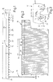
- 1, 2 consists of a base or base profile 12 and cooling plates 16 of length a of 240 mm and height b of 120 mm which are clamped in insert grooves 14.
- the sheet used for this with a thickness d of 1.4 mm is corrugated in the direction of its longitudinal axis A (FIG. 6); this can be seen above all from FIGS. 6, 7 on the basis of waves 18.
- Their shaft tips 19 each determine a parallel plane E on both sides of that longitudinal axis A. The distance between the planes E corresponds to the width i of the insert grooves 14.
- the basic or base profile 12 with a length e of 583 mm, a width f of 70 mm and a height h of 15 mm is, for example, extruded from AlMgSi O.5 F 22.
- Both the surface 20 and the end faces 21 of the base or base profile 12 are flat, whereas the bottom surface 22 according to FIG. 3, which has transverse insert grooves 14 extending transversely to its longitudinal extent, between adjacent insert grooves 14 of constant width i of approximately 1.6 mm flanking - ribs 24 transverse indentations 26 offers inwardly tapering width n.
- the distance q between the insert grooves 14 measures 11 mm, the height distance t between the lowest and the lowest of the transverse indentation 26 here 0.7 mm; the depth z of the transverse recess 26, which is deeper in relation to the insertion groove 14, is 5 mm.
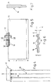
- FIGS. 8 to 10 shows, as cooling plate 16 a, a longitudinally sawtooth-profiled sheet metal with shoulder shoulders 28 running transversely to the longitudinal axis A on its two outer surfaces, each of which extends from a surface piece 29 parallel to the longitudinal axis A, one of which extends at an acute angle w connects to desk surface 30 inclined to longitudinal axis A.
- the shoulder shoulders 28 are offset by a dimension x in the longitudinal direction - successively in the longitudinal section.
Landscapes
- Engineering & Computer Science (AREA)
- Physics & Mathematics (AREA)
- Thermal Sciences (AREA)
- Mechanical Engineering (AREA)
- General Engineering & Computer Science (AREA)
- Cooling Or The Like Of Semiconductors Or Solid State Devices (AREA)
- Devices That Are Associated With Refrigeration Equipment (AREA)
- Cooling Or The Like Of Electrical Apparatus (AREA)
- Glass Compositions (AREA)
Abstract
Description
- Die Erfindung betrifft einen Kühlkörper fur Halbleiterbauelemente od.dgl. Geräte mit in Abstand zueinander an ein Grundprofil aus stranggepreßtem Aluminium oder anderem Leichtmetall angeschlossenen und davon aufragenden Kühlrippen, die jeweils in einer Einsatznut od.dgl. Ausnehmung des Grundprofils festliegen.
- Die DE-PS 35 18 310 beschreibt stranggepreßte Vollprofile mit seitlichen Ausformungen als Kühlrippen, die in Einsatznuten der Grundplatte formschlüssig eingesetzt werden. Zudem erwähnt diese Druckschrift sog. Rippenverhältnisse (Verhältnis der Höhe zum lichten Abstand) von mehr als 12 : 1, womit die Grenze der erreichbaren Oberfläche bestimmt ist. Sowohl technische als auch wirtschaftliche Gesichtspunkte erfordern je nach Rippenhöhe eine Mindestrippendicke. Die Fertigung eines Kühlkörpers mit dünnen Rippen bei hoher Rippenzahl geht wegen des größeren Aufwandes zu Lasten der Wirtschaftlichkeit.
- Gegenüber der Lehre der DE-PS 35 18 310 stellt eine gattungsgemäßen Kühlkörper mit zwischen zwei -- mit der Grundplatte eine Art Rechteckrinne ergebenden -- Flankenwänden verlaufenden Kühlrippen nach der EP-A-O 483 058 der Anmelderin eine Verbesserung dar. Sowohl die Innenflächen der Flankenwände als auch die Außenflächen der Kühlrippen sind mit Riffelungen ausgestattet, die parallel zur Grundplatte verlaufen. Die beiden Rippenwände jeder Kühlrippe sind an einem Ende durch einen in der Einsatznut der Grundplatte festlegbaren Kupplungssockel und am anderen Ende durch einen Quersteg verbunden; ein weiterer Quersteg teilt den Rippenhohlraum etwa in halber Höhe in zwei Kanäle. Mit diesem Kühlkörper sollten sowohl die Wanddicken von Kühlrippen als auch der Herstellungsaufwand für den Kühlkörper vermindert werden.
- Im Gegensatz zu Kühlkörpern für Zwangsbelüftung bzw. erzwungene Konvektion lassen Kühlkörper fur freie Konvektion Rippen geringer Dicke und relativ großer Höhe zu. Als Strangpreßprofile sind solche Rippen nicht herstellbar. Der Einsatz von normalen Blechen ist nicht möglich, da die hierfür erforderliche geringe Weite der Einsatznuten des Grund- oder Basisprofils strangpreßtechnisch nicht realisiert zu werden vermag.
- In Kenntnis dieses Standes der Technik hat sich der Erfinder die Aufgabe gestellt, die Herstellung des gattungsgemäßen Kühlkörpers freier Konvektion zu verbessern.
- Zur Lösung dieser Aufgabe führt die Lehre nach dem unabhängigen Anspruch; die Unteransprüche geben günstige Weiterbildungen an.
- Erfindungsgemäß sind die Kühlrippen jeweils als Kühlplatten aus einem dünnen Werkstoffstreifen ausgebildet, und ihr Längsschnitt ist zumindest im Bereich ihrer Verbindung mit dem Grundprofil teilweise durch Profilierung erweitert; hierdurch wird die Verbindung mit Einsatznuten preßbarer Dimensionierung ermöglicht.
- Bei einer Ausgestaltung des Kühlkörpers ist die Kühlplatte aus einem Blech wellenartig ausgeformt, wobei der die Längsachse querende Abstand zwischen zwei von den Wellenspitzen bestimmten Ebenen der Breite jener Einsatznuten entspricht.
- Eine weitere Ausgestaltung zeigt eine Kühlplatte, die längsschnittlich unter Bildung schulterartiger Absätze sägezahnartig profiliert ist.
- Dank dieser Maßgaben werden also zwei Lösungswege angeboten, zum einen der Einsatz eines wellenartig ausgeformten Bleches, zum anderen die Verwendung eines sägezahnförmig verformten Bleches, wobei das eingefügte Blech wesentlich länger sein kann als das Grundprofil.
- Nach einem weiteren Merkmal der Erfindung verläuft zwischen zwei benachbarten schulterartigen Absätzen eine längsschnittliche Pultfläche, die an der Spitze des einen Absatzes endet. Die andere Seite der Pultfläche kann in ein achsparalleles Flächenstück übergehen.
- Im Rahmen der Erfindung liegt es, daß das Grund- oder Basisprofil zwischen jeweils zwei Einsatznuten eine Quereinformung anbietet, die sich einwärts verjüngen kann.
- Zudem hat es sich als günstig erwiesen, diese Quereinformung tiefer in das Grundprofil hineinzuführen als die Einsatznut.
- Weitere Vorteile, Merkmale und Einzelheiten der Erfindung ergeben sich aus der nachfolgenden Beschreibung bevorzugter Ausführungsbeispiele sowie anhand der Zeichnung; diese zeigt in:
- Fig. 1, 4, 8:
- teilweise Seitenansichten von Ausführungen eines Kühlkörpers aus einem Grundprofil und daran festgelegten Kühlplatten;
- Fig. 2, 5:
- zwei Frontansichten zu den in Fig. 1, 4 dargestellten Kühlkörpern (Fig. 5 teilweise geschnitten gemäß Linie V-V der Fig. 4);
- Fig. 3:
- einen vergrößerten Ausschnitt aus Fig nach deren Feld III;
- Fig. 6, 7:
- vergrößerte Querschnitte der Fig. 5. nach deren Schnittlinien VI-VI bzw. VII-VII;
- Fig. 9:
- einen Abschnitt aus einer Frontansicht zu Fig. 8;
- Fig. 10:
- den Schnitt durch Fig. 9 nach deren Linie X-X.
- Ein Kühlkörper 10 besteht gemäß Fig. 1, 2 aus einem Grund- oder Basisprofil 12 und von diesem in Einsatznuten 14 klemmend gehaltenen Kühlplatten 16 der Länge a von 240 mm und der Höhe b von 120 mm. Das dafür eingesetzte Blech der Dicke d von 1,4 mm ist in Richtung seiner Längsachse A (Fig. 6) gewellt; dies lassen vor allem die Fig. 6, 7 anhand von Wellen 18 erkennen. Deren Wellenspitzen 19 bestimmen an beiden Seiten jener Längsachse A jeweils eine dazu parallele Ebene E. Der Abstand der Ebenen E voneinander entspricht der Breite i der Einsatznuten 14.
- Das Grund- oder Basisprofil 12 einer Lange e von 583 mm, einer Breite f von 70 mm und einer Höhe h von 15 mm ist beispielsweise aus AlMgSi O.5 F 22 stranggepreßt.
- Sowohl die Oberfläche 20 als auch die Stirnflächen 21 des Grund- oder Basisprofils 12 sind eben, wohingegen die -- jene quer zu seiner Längserstreckung verlaufenden Einsatznuten 14 aufweisende -- Unterfläche 22 gemäß Fig. 3 zwischen -- benachbarte Einsatznuten 14 stetiger Breite i von etwa 1,6 mm flankierenden -- Rippen 24 Quereinformungen 26 sich einwärts verjüngender Weite n anbietet. Der Abstand q zwischen den Einsatznuten 14 mißt 11 mm, der Höhenabstand t zwischen deren Tiefstem und dem Tiefsten der Quereinformung 26 hier 0,7 mm; die Tiefe z der im Verhältnis zur Einsatznut 14 tieferen Quereinformung 26 beträgt 5 mm.
- Dies Ausführungsbeispiel der Fig. 8 bis 10 zeigt als Kühlplatte 16a ein längsschnittlich sägezahnartig profiliertes Blech mit an seinen beiden Außenflächen quer zur Längsachse A verlaufenden Schulterabsätzen 28, von denen jeweils ein zur Längsachse A paralleles Flächenstück 29 ausgeht, an das eine in einem spitzen Winkel w zur Längsachse A geneigte Pultfläche 30 anschließt. Die Schulterabsätze 28 sind in Längsrichtung -- im Längsschnitt aufeinander folgend -- um ein Maß x versetzt.
Claims (8)
- Kühlkörper für Halbleiterbauelemente od.dgl. Geräte mit in Abstand zueinander an ein Grundprofil aus stranggepreßtem Aluminium oder anderem Leichtmetall angeschlossenen und davon abragenden Kühlrippen, die jeweils in einer Einsatznut od.dgl. Ausnehmung des Grundprofils festliegen,
dadurch gekennzeichnet,
daß die Kühlrippen jeweils als Kühlplatte (16, 16a) aus einem dünnen (Dicke d) Werkstoffstreifen ausgebildet sind und ihr Längsschnitt zumindest im Bereich ihrer Verbindung mit dem Grundprofil teilweise durch Profilierung erweitert ist. - Kühlkörper nach Anspruch 1, dadurch gekennzeichnet, daß die Kühlplatte (16) aus einem Blech wellenartig ausgeformt ist, wobei der die Längsachse (A) querende Abstand zwischen zwei von den Wellenspitzen (19) bestimmten Ebenen (E) etwa der Breite (i) der Einsatznuten (14) entspricht.
- Kühlkörper nach Anspruch 1, dadurch gekennzeichnet, daß der Längsschnitt der Kühlplatte (16a) unter Bildung schulterartiger Absätze (28) sägezahnartig profiliert ist, wobei der die Längsachse (A) querende Abstand zwischen zwei von den Spitzen der schulterartigen Absätze (28) bestimmten Ebene (E) etwa der Breite (i) der Einsatznuten (14) entspricht.
- Kühlkörper nach Anspruch 1 oder 3, dadurch gekennzeichnet, daß zwischen zwei benachbarten schulterartigen Absätzen (28) eine längsschnittliche Pultfläche (30) verläuft, die an der Spitze des einen Absatzes endet.
- Kühlkörper nach Anspruch 3 oder 4, dadurch gekennzeichnet, daß die andere Seite der Pultfläche (30) in ein achsparalleles Flächenstück (29) übergeht.
- Kühlkörper nach wenigstens einem der Ansprüche 1 bis 5, dadurch gekennzeichnet, daß das Grundprofil (12) zwischen zwei benachbarten Einsatznuten (14) jeweils eine Quereinformung aufweist.
- Kühlkörper nach Anspruch 6, dadurch gekennzeichnet, daß sich der Querschnitt der Quereinformung (26) einwärts verjüngt.
- Kühlkörper nach Anspruch 6 oder 7, dadurch gekennzeichnet, daß das Tiefste der Einsatznut (14) und das Tiefste der Quereinformung (26) einen Abstand (d) bestimmen.
Applications Claiming Priority (2)
| Application Number | Priority Date | Filing Date | Title |
|---|---|---|---|
| DE29507286U DE29507286U1 (de) | 1995-05-04 | 1995-05-04 | Kühlkörper für Halbleiterbauelemente o.dgl. Geräte |
| DE29507286U | 1995-05-04 |
Publications (3)
| Publication Number | Publication Date |
|---|---|
| EP0741409A2 true EP0741409A2 (de) | 1996-11-06 |
| EP0741409A3 EP0741409A3 (de) | 1997-06-11 |
| EP0741409B1 EP0741409B1 (de) | 2001-10-17 |
Family
ID=8007507
Family Applications (1)
| Application Number | Title | Priority Date | Filing Date |
|---|---|---|---|
| EP96810261A Expired - Lifetime EP0741409B1 (de) | 1995-05-04 | 1996-04-24 | Kühlkörper für Halbleiterbauelemente |
Country Status (8)
| Country | Link |
|---|---|
| US (2) | US6234246B1 (de) |
| EP (1) | EP0741409B1 (de) |
| AT (1) | ATE207242T1 (de) |
| DE (2) | DE29507286U1 (de) |
| DK (1) | DK0741409T3 (de) |
| ES (1) | ES2162011T3 (de) |
| PT (1) | PT741409E (de) |
| TR (1) | TR199600281A2 (de) |
Families Citing this family (16)
| Publication number | Priority date | Publication date | Assignee | Title |
|---|---|---|---|---|
| JP3552047B2 (ja) * | 2000-10-25 | 2004-08-11 | 古河電気工業株式会社 | ヒートシンク、その製造方法、および、押圧治具 |
| WO2002070977A1 (en) | 2001-03-01 | 2002-09-12 | Norsk Hydro Asa | Heat exchanger having fins |
| US8464781B2 (en) | 2002-11-01 | 2013-06-18 | Cooligy Inc. | Cooling systems incorporating heat exchangers and thermoelectric layers |
| US7591302B1 (en) | 2003-07-23 | 2009-09-22 | Cooligy Inc. | Pump and fan control concepts in a cooling system |
| US7188661B2 (en) * | 2003-11-13 | 2007-03-13 | Thermamasters, Llc | Process for joining members of a heat transfer assembly and assembly formed thereby |
| US7077188B2 (en) * | 2004-09-27 | 2006-07-18 | Shyh-Ming Chen | Heat dissipating device with heat conductive tubes |
| US7036566B1 (en) * | 2005-10-06 | 2006-05-02 | Tsung-Hsien Huang | Heat dissipating module |
| FR2898668B1 (fr) * | 2006-03-15 | 2008-06-27 | Ferraz Date Ind Soc Par Action | Echangeur de chaleur destine au refroidissement d'un composant electronique et son procede de fabrication |
| CN101715536A (zh) * | 2007-05-02 | 2010-05-26 | 固利吉股份有限公司 | 用于电子冷却应用的微管/多端口逆流散热器设计 |
| TWI312046B (en) * | 2007-08-24 | 2009-07-11 | Ama Precision Inc | Led base with heat fins |
| US9297571B1 (en) | 2008-03-10 | 2016-03-29 | Liebert Corporation | Device and methodology for the removal of heat from an equipment rack by means of heat exchangers mounted to a door |
| US20100065248A1 (en) * | 2008-09-17 | 2010-03-18 | Asia Vital Components Co., Ltd. | Heat sink |
| US20110073292A1 (en) * | 2009-09-30 | 2011-03-31 | Madhav Datta | Fabrication of high surface area, high aspect ratio mini-channels and their application in liquid cooling systems |
| USD634278S1 (en) * | 2009-10-15 | 2011-03-15 | Sapa Ab | Heat sink |
| EP2894954B1 (de) * | 2013-12-06 | 2021-08-11 | Marchesi Metal Technology (Suzhou) Co., Ltd | Wärmeableitendes gehäuse mit integrierten kühlrippen |
| JP2024086427A (ja) * | 2022-12-16 | 2024-06-27 | 日本発條株式会社 | 放熱構造体およびその製造方法 |
Family Cites Families (14)
| Publication number | Priority date | Publication date | Assignee | Title |
|---|---|---|---|---|
| US2404166A (en) * | 1943-10-02 | 1946-07-16 | Emma G Danilla | Device for use in roasting poultry and the like |
| FR1462160A (fr) * | 1963-05-28 | 1966-04-15 | Chausson Usines Sa | Procédé de fabrication d'un élément échangeur de chaleur, élément obtenu par ce procédé et application de cet élément à la constitution d'échangeurs de chaleur particuliers |
| DE2502472C2 (de) * | 1975-01-22 | 1982-09-02 | Siemens AG, 1000 Berlin und 8000 München | Kühlkörper für Thyristoren |
| JPS5585049A (en) * | 1978-12-21 | 1980-06-26 | Toshiba Corp | Cooling fin |
| JPS57196552A (en) * | 1981-05-27 | 1982-12-02 | Nec Corp | Radiator |
| DE3518310A1 (de) * | 1985-05-22 | 1986-11-27 | Aluminium-Walzwerke Singen Gmbh, 7700 Singen | Kuehlkoerper fuer halbleiterbauelemente und verfahren zu seiner herstellung |
| DE3814145C2 (de) * | 1988-04-27 | 1998-07-23 | Hess Joachim | Vorrichtung zum Zuführen oder Abführen von Wärme |
| JPH06198383A (ja) * | 1992-09-21 | 1994-07-19 | Hideaki Serizawa | 放熱板及びその製作方法 |
| US5542176A (en) * | 1992-09-21 | 1996-08-06 | Hideaki Serizawa | Radiation plate and method of producing the same |
| DE4314663A1 (de) * | 1993-05-04 | 1994-11-10 | Alusuisse Lonza Services Ag | Kühlkörper für Halbleiterbauelemente |
| JP2701692B2 (ja) * | 1993-05-06 | 1998-01-21 | 日本軽金属株式会社 | ヒートシンク及びその製造方法 |
| US5435384A (en) * | 1994-07-20 | 1995-07-25 | Wu; Chung | Heat dissipating plate |
| US5499450A (en) * | 1994-12-19 | 1996-03-19 | Jacoby; John | Method of manufacturing a multiple pin heatsink device |
| US5535515A (en) * | 1995-03-13 | 1996-07-16 | Jacoby; John | Method of manufacturing a stress-free heatsink assembly |
-
1995
- 1995-05-04 DE DE29507286U patent/DE29507286U1/de not_active Expired - Lifetime
-
1996
- 1996-04-03 TR TR96/00281A patent/TR199600281A2/xx unknown
- 1996-04-05 US US08/628,805 patent/US6234246B1/en not_active Expired - Fee Related
- 1996-04-24 ES ES96810261T patent/ES2162011T3/es not_active Expired - Lifetime
- 1996-04-24 PT PT96810261T patent/PT741409E/pt unknown
- 1996-04-24 AT AT96810261T patent/ATE207242T1/de not_active IP Right Cessation
- 1996-04-24 EP EP96810261A patent/EP0741409B1/de not_active Expired - Lifetime
- 1996-04-24 DE DE59607913T patent/DE59607913D1/de not_active Expired - Fee Related
- 1996-04-24 DK DK96810261T patent/DK0741409T3/da active
-
1997
- 1997-08-20 US US08/915,187 patent/US5950721A/en not_active Expired - Fee Related
Also Published As
| Publication number | Publication date |
|---|---|
| ATE207242T1 (de) | 2001-11-15 |
| EP0741409A3 (de) | 1997-06-11 |
| ES2162011T3 (es) | 2001-12-16 |
| DE29507286U1 (de) | 1995-07-20 |
| US6234246B1 (en) | 2001-05-22 |
| DK0741409T3 (da) | 2002-02-11 |
| US5950721A (en) | 1999-09-14 |
| PT741409E (pt) | 2002-02-28 |
| TR199600281A2 (tr) | 1996-11-21 |
| EP0741409B1 (de) | 2001-10-17 |
| DE59607913D1 (de) | 2001-11-22 |
Similar Documents
| Publication | Publication Date | Title |
|---|---|---|
| EP0741409B1 (de) | Kühlkörper für Halbleiterbauelemente | |
| DE3518310C2 (de) | ||
| DE69509273T2 (de) | Aufhängevorrichtung | |
| EP0892123A2 (de) | Träger, insbesondere ein aus einer Leichtmetallegierung stranggespresstes Hohlprofil eckigen Querschnitts, und Bausatz aus derartigen Trägern | |
| DE10200019B4 (de) | Kühlkörper für Halbleiterbauelemente, Verfahren zu dessen Herstellung und Werkzeug zur Durchführung des Verfahrens | |
| DE2241407A1 (de) | Waermetauscher und verfahren zu ihrer herstellung | |
| EP0483058B1 (de) | Kühlkörper für Halbleiterbauelemente | |
| EP0734062B1 (de) | Kühlkörper für Halbleiterbauelemente od. dgl. | |
| DE4314663A1 (de) | Kühlkörper für Halbleiterbauelemente | |
| DE10016012B4 (de) | Verbundprofil für Fenster, Fassaden, Türen oder Lichtdächer | |
| EP2054930A1 (de) | Kühlkörper für halbleiterbauelemente od. dgl. geräte sowie verfahren zu seiner herstellung | |
| EP0795905B1 (de) | Kühlkörper für Halbleiterbauelemente od. dgl. Einrichtungen | |
| EP3643846B1 (de) | Schiene | |
| EP0032408A2 (de) | Wärmeisolierender Profilkörper | |
| DE2610466B1 (de) | Isolationsprofil fuer ein waermeisolierendes aluminiumprofil | |
| EP0430921A1 (de) | Wand, die aus kastenförmigen Plattenelementen besteht | |
| DE29602366U1 (de) | Kühlkörper für Halbleiterbauelemente o.dgl. | |
| DE29601776U1 (de) | Kühlkörper für Halbleiterbauelemente o.dgl. | |
| EP0960985A2 (de) | I-förmiger Träger für Gebäudekonstruktionen | |
| DE10056387B4 (de) | Kühlvorrichtung und Verfahren zu deren Herstellung sowie Vorrichtung zur Durchführung des Verfahrens | |
| DE19841911A1 (de) | Kühlkörper für im wesentlichen L-förmige oder T-förmige Kühlrippen | |
| DE19830512A1 (de) | Kühlkörper mit Querrippen | |
| DE19616017C2 (de) | Verbindung von wenigstens zwei Profilteilen | |
| DE202013104990U1 (de) | Kühlkörper | |
| WO2000003574A2 (de) | Kühlkörper mit querrippen |
Legal Events
| Date | Code | Title | Description |
|---|---|---|---|
| PUAI | Public reference made under article 153(3) epc to a published international application that has entered the european phase |
Free format text: ORIGINAL CODE: 0009012 |
|
| AK | Designated contracting states |
Kind code of ref document: A2 Designated state(s): AT BE DE DK ES FR GB GR IE IT NL PT SE |
|
| PUAL | Search report despatched |
Free format text: ORIGINAL CODE: 0009013 |
|
| AK | Designated contracting states |
Kind code of ref document: A3 Designated state(s): AT BE DE DK ES FR GB GR IE IT NL PT SE |
|
| 17P | Request for examination filed |
Effective date: 19971211 |
|
| 17Q | First examination report despatched |
Effective date: 19990329 |
|
| GRAG | Despatch of communication of intention to grant |
Free format text: ORIGINAL CODE: EPIDOS AGRA |
|
| GRAG | Despatch of communication of intention to grant |
Free format text: ORIGINAL CODE: EPIDOS AGRA |
|
| GRAH | Despatch of communication of intention to grant a patent |
Free format text: ORIGINAL CODE: EPIDOS IGRA |
|
| ITF | It: translation for a ep patent filed | ||
| GRAH | Despatch of communication of intention to grant a patent |
Free format text: ORIGINAL CODE: EPIDOS IGRA |
|
| GRAA | (expected) grant |
Free format text: ORIGINAL CODE: 0009210 |
|
| AK | Designated contracting states |
Kind code of ref document: B1 Designated state(s): AT BE DE DK ES FR GB GR IE IT NL PT SE |
|
| REF | Corresponds to: |
Ref document number: 207242 Country of ref document: AT Date of ref document: 20011115 Kind code of ref document: T |
|
| RAP2 | Party data changed (patent owner data changed or rights of a patent transferred) |
Owner name: ALCAN TECHNOLOGY & MANAGEMENT AG |
|
| REG | Reference to a national code |
Ref country code: IE Ref legal event code: FG4D Free format text: GERMAN |
|
| REF | Corresponds to: |
Ref document number: 59607913 Country of ref document: DE Date of ref document: 20011122 |
|
| GBT | Gb: translation of ep patent filed (gb section 77(6)(a)/1977) |
Effective date: 20011106 |
|
| REG | Reference to a national code |
Ref country code: ES Ref legal event code: FG2A Ref document number: 2162011 Country of ref document: ES Kind code of ref document: T3 |
|
| REG | Reference to a national code |
Ref country code: GB Ref legal event code: IF02 |
|
| NLT2 | Nl: modifications (of names), taken from the european patent patent bulletin |
Owner name: ALCAN TECHNOLOGY & MANAGEMENT AG |
|
| REG | Reference to a national code |
Ref country code: DK Ref legal event code: T3 |
|
| REG | Reference to a national code |
Ref country code: PT Ref legal event code: SC4A Free format text: AVAILABILITY OF NATIONAL TRANSLATION Effective date: 20011122 |
|
| ET | Fr: translation filed | ||
| REG | Reference to a national code |
Ref country code: GR Ref legal event code: EP Ref document number: 20020400064 Country of ref document: GR |
|
| PLBE | No opposition filed within time limit |
Free format text: ORIGINAL CODE: 0009261 |
|
| STAA | Information on the status of an ep patent application or granted ep patent |
Free format text: STATUS: NO OPPOSITION FILED WITHIN TIME LIMIT |
|
| 26N | No opposition filed | ||
| PGFP | Annual fee paid to national office [announced via postgrant information from national office to epo] |
Ref country code: IE Payment date: 20090427 Year of fee payment: 14 Ref country code: ES Payment date: 20090427 Year of fee payment: 14 Ref country code: DK Payment date: 20090428 Year of fee payment: 14 |
|
| PGFP | Annual fee paid to national office [announced via postgrant information from national office to epo] |
Ref country code: SE Payment date: 20090429 Year of fee payment: 14 Ref country code: PT Payment date: 20090407 Year of fee payment: 14 Ref country code: NL Payment date: 20090423 Year of fee payment: 14 Ref country code: IT Payment date: 20090428 Year of fee payment: 14 Ref country code: FR Payment date: 20090417 Year of fee payment: 14 Ref country code: DE Payment date: 20090429 Year of fee payment: 14 Ref country code: AT Payment date: 20090401 Year of fee payment: 14 |
|
| PGFP | Annual fee paid to national office [announced via postgrant information from national office to epo] |
Ref country code: BE Payment date: 20090528 Year of fee payment: 14 |
|
| PGFP | Annual fee paid to national office [announced via postgrant information from national office to epo] |
Ref country code: GR Payment date: 20090428 Year of fee payment: 14 Ref country code: GB Payment date: 20090429 Year of fee payment: 14 |
|
| BERE | Be: lapsed |
Owner name: *ALUSUISSE TECHNOLOGY & MANAGEMENT A.G. Effective date: 20100430 |
|
| REG | Reference to a national code |
Ref country code: PT Ref legal event code: MM4A Free format text: LAPSE DUE TO NON-PAYMENT OF FEES Effective date: 20101025 |
|
| REG | Reference to a national code |
Ref country code: NL Ref legal event code: V1 Effective date: 20101101 |
|
| EUG | Se: european patent has lapsed | ||
| REG | Reference to a national code |
Ref country code: DK Ref legal event code: EBP |
|
| GBPC | Gb: european patent ceased through non-payment of renewal fee |
Effective date: 20100424 |
|
| REG | Reference to a national code |
Ref country code: IE Ref legal event code: MM4A |
|
| REG | Reference to a national code |
Ref country code: FR Ref legal event code: ST Effective date: 20101230 |
|
| PG25 | Lapsed in a contracting state [announced via postgrant information from national office to epo] |
Ref country code: NL Free format text: LAPSE BECAUSE OF NON-PAYMENT OF DUE FEES Effective date: 20101101 Ref country code: IE Free format text: LAPSE BECAUSE OF NON-PAYMENT OF DUE FEES Effective date: 20100426 Ref country code: AT Free format text: LAPSE BECAUSE OF NON-PAYMENT OF DUE FEES Effective date: 20100424 |
|
| PG25 | Lapsed in a contracting state [announced via postgrant information from national office to epo] |
Ref country code: PT Free format text: LAPSE BECAUSE OF NON-PAYMENT OF DUE FEES Effective date: 20101025 Ref country code: DE Free format text: LAPSE BECAUSE OF NON-PAYMENT OF DUE FEES Effective date: 20101103 |
|
| PG25 | Lapsed in a contracting state [announced via postgrant information from national office to epo] |
Ref country code: IT Free format text: LAPSE BECAUSE OF NON-PAYMENT OF DUE FEES Effective date: 20100424 Ref country code: BE Free format text: LAPSE BECAUSE OF NON-PAYMENT OF DUE FEES Effective date: 20100430 Ref country code: GR Free format text: LAPSE BECAUSE OF NON-PAYMENT OF DUE FEES Effective date: 20101103 Ref country code: GB Free format text: LAPSE BECAUSE OF NON-PAYMENT OF DUE FEES Effective date: 20100424 |
|
| PG25 | Lapsed in a contracting state [announced via postgrant information from national office to epo] |
Ref country code: DK Free format text: LAPSE BECAUSE OF NON-PAYMENT OF DUE FEES Effective date: 20100503 |
|
| REG | Reference to a national code |
Ref country code: ES Ref legal event code: FD2A Effective date: 20110715 |
|
| PG25 | Lapsed in a contracting state [announced via postgrant information from national office to epo] |
Ref country code: ES Free format text: LAPSE BECAUSE OF NON-PAYMENT OF DUE FEES Effective date: 20110705 |
|
| PG25 | Lapsed in a contracting state [announced via postgrant information from national office to epo] |
Ref country code: ES Free format text: LAPSE BECAUSE OF NON-PAYMENT OF DUE FEES Effective date: 20100425 |
|
| PG25 | Lapsed in a contracting state [announced via postgrant information from national office to epo] |
Ref country code: FR Free format text: LAPSE BECAUSE OF NON-PAYMENT OF DUE FEES Effective date: 20100430 |
|
| PG25 | Lapsed in a contracting state [announced via postgrant information from national office to epo] |
Ref country code: SE Free format text: LAPSE BECAUSE OF NON-PAYMENT OF DUE FEES Effective date: 20100425 |