EP0741421A2 - Organe d'entraînement par des vibrations - Google Patents
Organe d'entraînement par des vibrations Download PDFInfo
- Publication number
- EP0741421A2 EP0741421A2 EP96302447A EP96302447A EP0741421A2 EP 0741421 A2 EP0741421 A2 EP 0741421A2 EP 96302447 A EP96302447 A EP 96302447A EP 96302447 A EP96302447 A EP 96302447A EP 0741421 A2 EP0741421 A2 EP 0741421A2
- Authority
- EP
- European Patent Office
- Prior art keywords
- vibration actuator
- side portions
- frame side
- vibration
- elastic member
- Prior art date
- Legal status (The legal status is an assumption and is not a legal conclusion. Google has not performed a legal analysis and makes no representation as to the accuracy of the status listed.)
- Ceased
Links
Images


Classifications
-
- H—ELECTRICITY
- H02—GENERATION; CONVERSION OR DISTRIBUTION OF ELECTRIC POWER
- H02N—ELECTRIC MACHINES NOT OTHERWISE PROVIDED FOR
- H02N2/00—Electric machines in general using piezoelectric effect, electrostriction or magnetostriction
- H02N2/0005—Electric machines in general using piezoelectric effect, electrostriction or magnetostriction producing non-specific motion; Details common to machines covered by H02N2/02 - H02N2/16
- H02N2/001—Driving devices, e.g. vibrators
- H02N2/003—Driving devices, e.g. vibrators using longitudinal or radial modes combined with bending modes
-
- H—ELECTRICITY
- H02—GENERATION; CONVERSION OR DISTRIBUTION OF ELECTRIC POWER
- H02N—ELECTRIC MACHINES NOT OTHERWISE PROVIDED FOR
- H02N2/00—Electric machines in general using piezoelectric effect, electrostriction or magnetostriction
- H02N2/02—Electric machines in general using piezoelectric effect, electrostriction or magnetostriction producing linear motion, e.g. actuators; Linear positioners ; Linear motors
- H02N2/026—Electric machines in general using piezoelectric effect, electrostriction or magnetostriction producing linear motion, e.g. actuators; Linear positioners ; Linear motors by pressing one or more vibrators against the driven body
-
- H—ELECTRICITY
- H02—GENERATION; CONVERSION OR DISTRIBUTION OF ELECTRIC POWER
- H02N—ELECTRIC MACHINES NOT OTHERWISE PROVIDED FOR
- H02N2/00—Electric machines in general using piezoelectric effect, electrostriction or magnetostriction
- H02N2/02—Electric machines in general using piezoelectric effect, electrostriction or magnetostriction producing linear motion, e.g. actuators; Linear positioners ; Linear motors
- H02N2/028—Electric machines in general using piezoelectric effect, electrostriction or magnetostriction producing linear motion, e.g. actuators; Linear positioners ; Linear motors along multiple or arbitrary translation directions, e.g. XYZ stages
-
- H—ELECTRICITY
- H02—GENERATION; CONVERSION OR DISTRIBUTION OF ELECTRIC POWER
- H02N—ELECTRIC MACHINES NOT OTHERWISE PROVIDED FOR
- H02N2/00—Electric machines in general using piezoelectric effect, electrostriction or magnetostriction
- H02N2/10—Electric machines in general using piezoelectric effect, electrostriction or magnetostriction producing rotary motion, e.g. rotary motors
- H02N2/103—Electric machines in general using piezoelectric effect, electrostriction or magnetostriction producing rotary motion, e.g. rotary motors by pressing one or more vibrators against the rotor
Definitions
- the present invention relates to a vibration actuator which is typically represented by an ultrasonic motor.
- the present invention relates, in particular, to a vibration motor which utilizes elliptic motion caused by synthesizing longitudinal vibration and bending vibration.
- a vibration actuator of this type generates a travelling vibration wave in a ring-shaped elastic member by exciting electro-mechanical converting elements, thereby driving a movable member (rotor) as a relative moving member which is in press contact with the elastic member.
- a vibration applying electro-mechanical converting element is disposed on one end portion of a rod-shaped elastic member, and a vibration absorbing electro-mechanical converting element for absorbing reflection of a travelling wave is disposed on the other end portion.
- the former vibration actuator is assembled in, e.g., a lens barrel of a camera, and is used for driving an AF lens upon rotation of the movable member.
- a blur prevention device for correcting an image blur by moving a portion of a photographing optical system in a plane substantially perpendicular to the optical axis.
- the former actuator cannot be applied to this device since its driving direction does not match.
- the latter actuator cannot be easily assembled in a cylindrical lens barrel, and makes the device bulky to attain driving operations in two directions, i.e., the X- and Y-directions in the plane perpendicular to the optical axis.
- An object of the present invention is to provide a vibration actuator which is capable of moving one-dimensionally or two-dimensionally on a flat plane and can be easily assembled in a cylindrical portion such as a lens barrel of a camera.
- a vibration actuator comprising an elastic member an outer shape of which is constituted by a polygon having at least one pair of parallel or substantially parallel opposed sides and formed in the shape of a frame, and electro-mechanical converting elements which are joined to the frame side portions of the elastic member containing the parallel sides and which generate the elliptic motion at predetermined positions in the frame side portions by generating vibrations in a longitudinal vibration mode and a bending vibration mode in the frame side portions with a drive signal.
- the electro-mechanical converting elements to be joined to the frame side portions can be arranged to be controlled independently of each other.
- each of the driving force extracting members has a curved-face contact portion to a relative moving member.
- the electro-mechanical converting elements are driven in response to a drive signal to generate vibrations in the longitudinal vibration mode and the bending vibration mode in the frame side portions of the elastic member, and the elliptic motion is generated at the predetermined positions in the frame side portions due to degeneration of the vibrations.
- the vibration actuator it becomes possible for the vibration actuator to move one-dimensionally or two-dimensionally on the flat plane parallel to the elastic member.
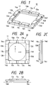
- Figs. 1 to 4 are views showing the first embodiment of a vibration actuator according to the present invention.
- Fig. 1 is a perspective view for showing the whole constitution of the vibration actuator of the present embodiment.
- Figs. 2A to 2C are views for showing three sides of the vibration actuator shown in Fig. 1.
- Figs. 3A to 3D are charts for explaining an operation of the vibration actuator of the present embodiment.
- Fig. 4 is a block diagram for showing the control effected on each electro-mechanical converting member.
- the vibration actuator 10 in the present embodiment is constituted by an elastic member 11 which is formed in the shape of a frame having an outer form constituted by a regular square, pairs of piezoelectric elements 12a and 13a, 12b and 13b, 12c and 13c, and 12d and 13d which function as electro-mechanical converting members to be jointed to the upper planes of the four frame side portions 11a, 11b, 11c and 11d of the elastic member 11, and driving force extracting members 14a, 14b, 14c and 14d disposed in the vicinities of the lower plane of the elastic member 11.
- the elastic member of the present embodiment is formed in the shape of a frame the outer form of which is a regular square, and is made of metallic or plastic elastic material. Since being formed in the shape of a frame, the elastic member 11 can easily be assembled in, for example, a lens barrel, and if the lens barrel is assembled to be accommodated within the apparatus, the size of the whole apparatus can be reduced to the minimum. It is noted that in Fig. 2A a position at which the lens barrel is assembled is shown by the dotted chain line.
- vibrations in the longitudinal vibration mode and the bending vibration mode are generated upon applying of a driving voltage onto the pairs of piezoelectric elements 12a and 13a, 12b and 13b, 12c and 13c, and 12d and 13d functioning as the electro-mechanical converting members. Then, since a synthetic motion of these vibrations generates an elliptic motion, it is important to make the longitudinal vibration mode coincident with the bending vibration mode as much as possible.
- the paired piezoelectric elements 12a and 13a, 12b and 13b, 12c and 13c, and 12d and 13d are respectively attached, in the present embodiment, by bonding.
- Each of these piezoelectric elements is formed into the shape of a thin plate by PZT, or the like.
- the pairs of piezoelectric elements 12a and 13a, 12b and 13b, 12c and 13c, and 12d and 13d which are respectively adjacent in the frame side portions 11a to 11d are arranged to be separated from each other with a predetermined distance therebetween.
- Each of the pairs of piezoelectric elements 12a and 13a, 12b and 13b, 12c and 13c, and 12d and 13d which are respectively adjacent in the frame side portions 11a to 11d is polarized. Then, two input voltages A and B having a phase difference of ⁇ /2 therebetween are applied onto the adjacent piezoelectric elements, respectively.
- the paired adjacent piezoelectric elements 12a and 13a, 12b and 13b, 12c and 13c, and 12d and 13d are polarized to have the polarity in the same direction.
- the high-frequency voltages A and B have a phase difference of the ⁇ /2 therebetween. Note that the polarities of each of the paired adjacent piezoelectric elements 12a and 13a, 12b and 13b, 12c and 13c, and 12d and 13d are opposite to each other.
- the driving force extracting members 14a, 14b, 14c and 14d are portions for extracting the elliptic motion which is generated by the synthetic vibration of the longitudinal vibration and the bending vibration of the elastic member 11. These driving force extracting members 11a to 11d make relative motion while contacting to a fixing member (a relative moving member) in pressure.
- the driving force extracting members 14a to 14d are disposed on the lower face of the elastic member 11 in the vicinities of the apexes of the regular square. These positions in the vicinities of the apexes should be kept away from the node positions of the longitudinal vibration which is generated in the elastic member 11 in order to extract the driving force efficiently. In the present embodiment, they are positioned at the antinodes of the vertical vibration in a substantially vertical direction with respect to a plane of movement, which vibration is generated in the bending vibration mode.
- the driving force extracting members 14a to 14d are made of silicon nitride in order to improve its abrasion-proof capability, and is made to have a curved-face tip end which serves as a contact portion so as not to impede the elliptic motion as far as possible. To this end, a decrease in the driving force due to the contact with the relative moving member is suppressed as much as possible so that the driving force can be extracted efficiently.
- Fig. 3A changes with time of the two high-frequency voltages A and B which are supplied to the vibration actuator 10 are indicated as t 1 to t 9 .
- Each transversal axis in Fig. 3A indicates an effective value of the high-frequency voltages A and B.
- Fig. 3B shows deformations of a cross-section of the vibration actuator 10, and indicates changes with time (t 1 to t 9 ) in the bending vibration which is generated in the vibration actuator 10.
- Fig. 3C shows deformations of the cross-section of the vibration actuator 10, and indicates changes with time (t 1 to t 9 ) in the extending and contracting vibrations which is generated in the vibration actuator 10.
- Fig. 3D shows changes with time (t 1 to t 9 ) in the elliptic motion which is generated in the driving force extracting members 14b and 14c of the vibration actuator 10.
- the high-frequency voltage A generates a positive voltage
- the high-frequency voltage B generates the same positive voltage in the same manner, as shown in Fig. 3A.
- the bending motions caused by the high-frequency voltages A and B are mutually negated so that the material particles Y1 and Z1 have the amplitude of zero.
- the expanding and contracting vibrations caused by the high-frequency voltages are generated in the direction of expansion.
- the material particles Y2 and Z2 show, as indicated by the arrows in the figure, the maximum expansion around the node X.
- the both vibrations mentioned above are compounded so that composition of motions of the material particles Y1 and Y2 makes a motion of the material particle Y and composition of motions of the material particles Z1 and Z2 makes a motion of the material particle Z.
- the high-frequency voltage B becomes zero and the high-frequency voltage A generates a positive voltage, as shown in Fig. 3A.
- a bending motion is generated by the high-frequency voltage A, and the material particle Y1 is amplified in the negative direction, while the material particle Z1 is amplified in the positive direction.
- expanding and contracting vibrations are generated by the high-frequency voltage A so that the material particle Y2 and the material particle Z2 are contracted, compared with those at the time t 1 .
- the both vibrations mentioned above are composited so that the material particles Y and Z advance in a counterclockwise direction, compared with those at the time t 1 .
- the high-frequency voltage A generates a positive voltage and the high-frequency voltage B generates the same negative voltage in the same manner, as shown in Fig. 3A.
- Fig. 3B bending motions caused by the high-frequency voltages A and B are synthesized and amplified, and the material particle Y1 is amplified in the negative direction, compared with that at the time t 2 , thereby indicating the maximum negative value of amplitude.
- the material particle Z1 is amplified in the positive direction, compared with that at the time t 2 , thereby indicating the maximum positive value of amplitude. Also, as shown in Fig.
- the expanding and contracting vibrations generated by the high-frequency voltages A and B are mutually negated so that the material particles Y2 and Z2 return to their original positions.
- the both vibrations mentioned above are composited so that the material particles Y and Z are moved in a counterclockwise direction, compared with those at the time t 2 .
- the high-frequency voltage A becomes zero and the high-frequency voltage B generates a negative voltage, as shown in Fig. 3A.
- a bending motion is generated by the high-frequency voltage B, the amplitude of the material particle Y1 is decreased, compared with that at the time t 3 , and the amplitude of the material particle Z1 is decreased, compared with that at the time t 3 .
- the expanding and contracting vibrations are generated by the high-frequency voltage B so that the material particles Y2 and Z2 are contracted.
- the both vibrations mentioned above are composited so that the material particles Y and Z are moved in a counterclockwise direction, compared with those at the time t 3 .
- the high-frequency voltage A generates a negative voltage and the high-frequency voltage B generates the same negative voltage in the same manner, as shown in Fig. 3A.
- Fig. 3B bending motions caused by the high-frequency voltages A and B are mutually negated so that the amplitudes of the material particles Y1 and Z1 become zero.
- Fig. 3C the expanding and contracting vibrations are generated by the high-frequency voltages A and B in the direction of contraction.
- the material particles Y2 and Z2 show the maximum contraction around the node X, as indicated by the arrows in the figure.
- the both vibrations mentioned above are composited so that the material particles Y and Z are moved in a counterclockwise direction, compared with those at the time t 4 .
- this vibration actuator generates the elliptic motion at the tip ends of the driving force extracting members 14b and 14c so as to generate the driving force. Therefore, when the tip ends of the driving force extracting members 14b and 14c are in press contact with the fixing portion, the elastic member 11 is self-propelled with respect to the fixing portion.
- the vibration actuator 10 in the present embodiment is driven by the following two controlling methods (1) and (2).
- controlling methods (1) and (2) are conducted independently of each other, but may be conducted simultaneously. If these controlling methods are conducted independently of each other, the vibration actuator is moved in the X direction and the Y direction independently, and if these methods are conducted simultaneously, the vibration actuator is moved in the synthesized direction of the X direction and the Y direction.
- Fig. 4 is a block diagram for showing application of the driving voltage onto the adjacent two piezoelectric elements 12a and 13a.
- an oscillator 20 functions to apply the high-frequency voltages A and B to the piezoelectric elements 12a to 12d and 13a to 13d.
- An output therefrom is branched into two. One is, after being phase-shifted only by ⁇ /2 in time by an X-directional phase shifter 21X and a Y-directional phase shifter 21Y, connected to an X-directional amplifier 22X and a Y-directional amplifier 22Y. The other is directly connected to an X-directional amplifier 23X and a Y-directional amplifier 23Y.
- the amplifiers 22X, 22Y, 23X and 23Y are connected to the piezoelectric elements 12a to 12d and 13a to 13d, respectively, through change-over switches 26a, 26b, 26c and 26d. It is noted that all of the change-over switches 26a to 26d are normally in a turned-on state.
- the basic arrangement of the present embodiment is that the driving voltage is applied so as to move the opposed piezoelectric elements in the same direction and the vibration actuator translates in one or both of the X and Y directions.
- the vibration actuator it is possible to rotate, not to translate, the vibration actuator by applying the driving voltage in such a manner as to move the opposed piezoelectric elements in the directions opposite to each other.
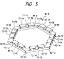
- Fig. 5 is a perspective view showing the second embodiment of a vibration actuator according to the present invention.
- a vibration actuator 10-1 of the present embodiment is constituted by an elastic member 11-1 which presents a frame shape having an outer form of a regular hexagon, piezoelectric elements 12-1a and 13-1a, 12-1b and 13-1b, 12-1c and 13-1c, 12-1d and 13-1d, 12-1e and 13-1e, and 12-1f and 13-1f which functions as electro-mechanical converting elements to be joined to the six frame side portions 11-1a, 11-1b, 11-1c, 11-1d, 11-1e and 11-1f of this elastic member 11-1, and driving force extracting members 14-1a, 14-1b, 14-1c, 14-1d, 14-1e and 14-1f which are disposed in the vicinities of the six apexes of the elastic member 11-1.
- the outer form of the elastic member is made polygonal so that the number of directions for installing the piezoelectric elements provided in the frame side portions of this elastic member is increased. For this reason, it is possible to increase the number of directions for moving the vibration actuator.
- a vibration actuator according to the present invention is not limited to those in the first and second embodiments fully described above. Various modifications and alterations are possible and they are also included in the present invention.
- the outer form of the frame-like elastic member is not limited to a regular square in the first embodiment or a regular hexagon in the second embodiment, but may be a polygon which has at least one pair of parallel or substantially parallel sides opposite to each other. It may be, for example, a trapezium, a rectangle, a regular octagon, or the like.
- piezoelectric elements are used as electro-mechanical converting elements.
- electrostriction elements magnetostriction elements, or the like.
- the vibration actuator of the present invention as a driving unit for an XY stage in a microscope, a driving unit for a feeding device of plotter sheets, and the like, in addition to as a driving unit for a vibration compensating apparatus.
Landscapes
- General Electrical Machinery Utilizing Piezoelectricity, Electrostriction Or Magnetostriction (AREA)
- Lens Barrels (AREA)
Applications Claiming Priority (2)
| Application Number | Priority Date | Filing Date | Title |
|---|---|---|---|
| JP7082543A JPH08280185A (ja) | 1995-04-07 | 1995-04-07 | 超音波アクチュエータ |
| JP82543/95 | 1995-04-07 |
Publications (2)
| Publication Number | Publication Date |
|---|---|
| EP0741421A2 true EP0741421A2 (fr) | 1996-11-06 |
| EP0741421A3 EP0741421A3 (fr) | 1996-11-13 |
Family
ID=13777427
Family Applications (1)
| Application Number | Title | Priority Date | Filing Date |
|---|---|---|---|
| EP96302447A Ceased EP0741421A3 (fr) | 1995-04-07 | 1996-04-04 | Organe d'entraínement par des vibrations |
Country Status (3)
| Country | Link |
|---|---|
| US (1) | US5760528A (fr) |
| EP (1) | EP0741421A3 (fr) |
| JP (1) | JPH08280185A (fr) |
Cited By (3)
| Publication number | Priority date | Publication date | Assignee | Title |
|---|---|---|---|---|
| EP1408560A3 (fr) * | 2002-10-07 | 2006-01-18 | Canon Kabushiki Kaisha | Appareil de commande pour un actionneur vibratoire, système d'actionnement vibratoire et méthode de commande d'un actionneur vibratoire |
| WO2015152716A1 (fr) * | 2014-04-04 | 2015-10-08 | Nederlandse Organisatie Voor Toegepast-Natuurwetenschappelijk Onderzoek Tno | Module actionneur pour actionner une charge |
| CN107404254A (zh) * | 2017-07-23 | 2017-11-28 | 中国科学院合肥物质科学研究院 | 一种摩擦力自配合的高对称性旋转压电马达及其控制方法 |
Families Citing this family (16)
| Publication number | Priority date | Publication date | Assignee | Title |
|---|---|---|---|---|
| US6046527A (en) * | 1996-07-05 | 2000-04-04 | Honeybee Robotics, Inc. | Ultrasonic positioner with multiple degrees of freedom of movement |
| US6078438A (en) * | 1997-04-14 | 2000-06-20 | Nikon Corporation | Vibration actuator and lens barrel |
| JP4282226B2 (ja) * | 2000-12-28 | 2009-06-17 | オリンパス株式会社 | カメラ |
| JP4726167B2 (ja) * | 2001-03-12 | 2011-07-20 | キヤノン株式会社 | 振動波駆動装置 |
| US7324148B2 (en) * | 2002-04-26 | 2008-01-29 | Olympus Optical Co., Ltd. | Camera and image pickup device unit used therefor having a sealing structure between a dust proofing member and an image pick up device |
| US7324149B2 (en) * | 2002-05-20 | 2008-01-29 | Olympus Optical Co., Ltd. | Camera and image pick-up device unit having an optical member that is vibrated to remove dust |
| JP2003348462A (ja) * | 2002-05-27 | 2003-12-05 | Olympus Optical Co Ltd | カメラ及び撮像素子ユニット |
| JP2004064554A (ja) * | 2002-07-30 | 2004-02-26 | Olympus Corp | カメラ及びこれに用いる撮像素子ユニット |
| JP2007524339A (ja) * | 2004-02-25 | 2007-08-23 | ナノモーション リミテッド | 多方向圧電モータ配置 |
| JP4756916B2 (ja) * | 2005-05-31 | 2011-08-24 | キヤノン株式会社 | 振動波モータ |
| JP5055832B2 (ja) * | 2006-05-16 | 2012-10-24 | オムロン株式会社 | 駆動装置、光走査型装置及び物体情報検知装置 |
| WO2008096797A1 (fr) | 2007-02-06 | 2008-08-14 | Sharp Kabushiki Kaisha | Dispositif d'entraînement, dispositif d'imagerie avec le dispositif d'entraînement, et matériel d'imagerie |
| JP4739357B2 (ja) * | 2007-02-06 | 2011-08-03 | シャープ株式会社 | 駆動装置、それを備えた撮像装置、及び撮像機器 |
| JP4209465B2 (ja) | 2007-02-21 | 2009-01-14 | パナソニック株式会社 | 駆動装置 |
| US7990459B2 (en) * | 2008-03-06 | 2011-08-02 | Olympus Imaging Corp. | Dust-proof filter unit, image pickup apparatus, and projection-type image display apparatus |
| JP5506552B2 (ja) | 2010-06-07 | 2014-05-28 | キヤノン株式会社 | 振動型アクチュエータの制御装置及び振動型アクチュエータの制御方法 |
Family Cites Families (15)
| Publication number | Priority date | Publication date | Assignee | Title |
|---|---|---|---|---|
| SU851565A1 (ru) * | 1979-10-29 | 1981-07-30 | Каунасский Политехнический Институтим. Ahtahaca Снечкуса | Вибродвигатель |
| US4398116A (en) * | 1981-04-30 | 1983-08-09 | Siemens Gammasonics, Inc. | Transducer for electronic focal scanning in an ultrasound imaging device |
| JPS62152380A (ja) * | 1985-12-25 | 1987-07-07 | Matsushita Electric Ind Co Ltd | 2方向微小変位装置 |
| US4742260A (en) * | 1986-02-06 | 1988-05-03 | Hiroshi Shimizu | Piezoelectrically driving device |
| EP0253375B1 (fr) * | 1986-07-15 | 1993-02-03 | Matsushita Electric Industrial Co., Ltd. | Organe d'actionnement piézo-électrique bidimentionnel |
| DE3733783A1 (de) * | 1986-10-06 | 1988-04-14 | Canon Kk | Vibrations-antriebsvorrichtung |
| US5146129A (en) * | 1986-12-01 | 1992-09-08 | Canon Kabushiki Kaisha | Vibration wave motor |
| JPH06106028B2 (ja) * | 1987-02-02 | 1994-12-21 | リオン株式会社 | 圧電共振モ−タ |
| JPH0648910B2 (ja) * | 1987-02-12 | 1994-06-22 | 日本電気株式会社 | 圧電モ−タ |
| JP2687233B2 (ja) * | 1989-02-10 | 1997-12-08 | キヤノン株式会社 | シート送り装置 |
| JPH0688680B2 (ja) * | 1989-03-20 | 1994-11-09 | 輝 林 | 記録媒体搬送装置及びこの装置に用いられる圧電素子付枠体 |
| JP3118251B2 (ja) * | 1990-11-21 | 2000-12-18 | ニスカ株式会社 | 超音波駆動装置及びその方法 |
| JPH04200282A (ja) * | 1990-11-29 | 1992-07-21 | Nikon Corp | 超音波モータの駆動装置 |
| JPH0741207B2 (ja) * | 1993-02-18 | 1995-05-10 | インターナショナル・ビジネス・マシーンズ・コーポレイション | マイクロアクチュエータ |
| EP0691692B1 (fr) * | 1994-07-05 | 1999-02-17 | Nikon Corporation | Moteur entraíné par des vibrations |
-
1995
- 1995-04-07 JP JP7082543A patent/JPH08280185A/ja active Pending
-
1996
- 1996-04-02 US US08/626,325 patent/US5760528A/en not_active Expired - Lifetime
- 1996-04-04 EP EP96302447A patent/EP0741421A3/fr not_active Ceased
Cited By (5)
| Publication number | Priority date | Publication date | Assignee | Title |
|---|---|---|---|---|
| EP1408560A3 (fr) * | 2002-10-07 | 2006-01-18 | Canon Kabushiki Kaisha | Appareil de commande pour un actionneur vibratoire, système d'actionnement vibratoire et méthode de commande d'un actionneur vibratoire |
| WO2015152716A1 (fr) * | 2014-04-04 | 2015-10-08 | Nederlandse Organisatie Voor Toegepast-Natuurwetenschappelijk Onderzoek Tno | Module actionneur pour actionner une charge |
| US9880194B2 (en) | 2014-04-04 | 2018-01-30 | Nederlandse Organisatie Voor Toegepast-Natuurwetenschappelijk Onderzoek Tno | Actuator module for actuating a load |
| CN107404254A (zh) * | 2017-07-23 | 2017-11-28 | 中国科学院合肥物质科学研究院 | 一种摩擦力自配合的高对称性旋转压电马达及其控制方法 |
| CN107404254B (zh) * | 2017-07-23 | 2023-09-22 | 中国科学院合肥物质科学研究院 | 一种摩擦力自配合的高对称性旋转压电马达及其控制方法 |
Also Published As
| Publication number | Publication date |
|---|---|
| JPH08280185A (ja) | 1996-10-22 |
| US5760528A (en) | 1998-06-02 |
| EP0741421A3 (fr) | 1996-11-13 |
Similar Documents
| Publication | Publication Date | Title |
|---|---|---|
| US5760528A (en) | Vibration actuator | |
| EP2327114B1 (fr) | Systèmes d'excitation semi-résonnants et procédés destiné à ceux-ci | |
| CN100438306C (zh) | 振动式驱动装置,其控制设备以及具有上述二者的电子设备 | |
| JPH07274552A (ja) | リニアモータ | |
| JP3412648B2 (ja) | 超音波モータ | |
| JP2002058266A (ja) | 超音波駆動装置 | |
| JP4197196B2 (ja) | 圧電アクチュエータもしくは超音波モータを利用したステージ及びこのステージを用いた電子機器、印刷装置 | |
| US6072266A (en) | Vibration actuator | |
| US5831370A (en) | Vibration actuator | |
| JPH07170768A (ja) | 超音波モータ | |
| US11711033B2 (en) | Piezoelectric motor with bending travelling wave | |
| JPH08182351A (ja) | 超音波アクチュエータ | |
| JP4976844B2 (ja) | 多自由度駆動装置および撮像装置 | |
| JP3200315B2 (ja) | 振動アクチュエータ | |
| JP2971971B2 (ja) | 超音波アクチュエータ | |
| JP4128248B2 (ja) | 超音波モータ | |
| JP3448783B2 (ja) | 超音波モータ | |
| JPH11235063A (ja) | 超音波モータを利用したステージ、および、これを用いた電子機器、印刷装置 | |
| JPH0993962A (ja) | 振動アクチュエータ | |
| JP4634174B2 (ja) | 超音波モータ及びそれを用いた電子機器 | |
| JPH05138128A (ja) | 加振機構 | |
| JP2000023475A (ja) | 振動アクチュエータ装置 | |
| JPH09322568A (ja) | 振動アクチュエータ | |
| JP2019080490A (ja) | 振動型アクチュエータ、レンズ鏡筒、カメラおよび制御方法 | |
| JPH1094277A (ja) | 振動アクチュエータ |
Legal Events
| Date | Code | Title | Description |
|---|---|---|---|
| PUAI | Public reference made under article 153(3) epc to a published international application that has entered the european phase |
Free format text: ORIGINAL CODE: 0009012 |
|
| PUAL | Search report despatched |
Free format text: ORIGINAL CODE: 0009013 |
|
| AK | Designated contracting states |
Kind code of ref document: A2 Designated state(s): DE FR GB |
|
| AK | Designated contracting states |
Kind code of ref document: A3 Designated state(s): DE FR GB |
|
| 17P | Request for examination filed |
Effective date: 19970110 |
|
| GRAG | Despatch of communication of intention to grant |
Free format text: ORIGINAL CODE: EPIDOS AGRA |
|
| 17Q | First examination report despatched |
Effective date: 19980505 |
|
| STAA | Information on the status of an ep patent application or granted ep patent |
Free format text: STATUS: THE APPLICATION HAS BEEN REFUSED |
|
| 18R | Application refused |
Effective date: 19981024 |