EP0741442A2 - Verfahren und Vorrichtung zur Handhabung und zum Aufwickeln von mehreren Teilen einer dynomoelektrischen Maschine - Google Patents
Verfahren und Vorrichtung zur Handhabung und zum Aufwickeln von mehreren Teilen einer dynomoelektrischen Maschine Download PDFInfo
- Publication number
- EP0741442A2 EP0741442A2 EP96113062A EP96113062A EP0741442A2 EP 0741442 A2 EP0741442 A2 EP 0741442A2 EP 96113062 A EP96113062 A EP 96113062A EP 96113062 A EP96113062 A EP 96113062A EP 0741442 A2 EP0741442 A2 EP 0741442A2
- Authority
- EP
- European Patent Office
- Prior art keywords
- wire
- cores
- conveyor
- transfer
- winders
- Prior art date
- Legal status (The legal status is an assumption and is not a legal conclusion. Google has not performed a legal analysis and makes no representation as to the accuracy of the status listed.)
- Withdrawn
Links
Images


Classifications
-
- H—ELECTRICITY
- H02—GENERATION; CONVERSION OR DISTRIBUTION OF ELECTRIC POWER
- H02K—DYNAMO-ELECTRIC MACHINES
- H02K15/00—Processes or apparatus specially adapted for manufacturing, assembling, maintaining or repairing of dynamo-electric machines
- H02K15/08—Forming windings by laying conductors into or around core parts
- H02K15/09—Forming windings by laying conductors into or around core parts by laying conductors into slotted rotors
-
- H—ELECTRICITY
- H02—GENERATION; CONVERSION OR DISTRIBUTION OF ELECTRIC POWER
- H02K—DYNAMO-ELECTRIC MACHINES
- H02K15/00—Processes or apparatus specially adapted for manufacturing, assembling, maintaining or repairing of dynamo-electric machines
-
- Y—GENERAL TAGGING OF NEW TECHNOLOGICAL DEVELOPMENTS; GENERAL TAGGING OF CROSS-SECTIONAL TECHNOLOGIES SPANNING OVER SEVERAL SECTIONS OF THE IPC; TECHNICAL SUBJECTS COVERED BY FORMER USPC CROSS-REFERENCE ART COLLECTIONS [XRACs] AND DIGESTS
- Y10—TECHNICAL SUBJECTS COVERED BY FORMER USPC
- Y10T—TECHNICAL SUBJECTS COVERED BY FORMER US CLASSIFICATION
- Y10T29/00—Metal working
- Y10T29/49—Method of mechanical manufacture
- Y10T29/49002—Electrical device making
- Y10T29/49009—Dynamoelectric machine
Definitions
- This invention relates to dynamo-electric machine parts manufacturing equipment, and more particularly to dynamo-electric machine parts manufacturing equipment which is capable of delivering and receiving dynamo-electric machine parts such as armatures or stators for electric motors, generators, alternators, or the like at the conveyor in a single alignment position, while simultaneously processing two or more other similar parts, and which reduces the amount of production time lost due to wire breakage at the winders.
- dynamo-electric machine parts manufacturing equipment and more particularly to dynamo-electric machine parts manufacturing equipment which is capable of delivering and receiving dynamo-electric machine parts such as armatures or stators for electric motors, generators, alternators, or the like at the conveyor in a single alignment position, while simultaneously processing two or more other similar parts, and which reduces the amount of production time lost due to wire breakage at the winders.
- the parts are serially conveyed on a conveyor to and from the single alignment position or transfer location.
- the parts are removed from the conveyor one at a time and held in a transfer mechanism until multiple parts can be supplied to the winder substantially simultaneously.
- two or more parts are processed substantially simultaneously by multiple winding mechanisms. While these parts are being processed, previously processed parts are delivered to the conveyor (preferably one at a time at the same single alignment position from which unprocessed parts are removed from the conveyor), and more unprocessed parts are received from the conveyor.
- the apparatus is able to deliver processed parts and receive unprocessed parts while the winder is operating, it saves undue delay in the production line.
- the conveyor only advances a step when it has received a processed part.
- any broken wire is immediately detected and controlled to prevent further inadvertent dispensing of that wire. For example, this may be done by retracting a broken wire relative to the associated dispenser so that continued motion of that dispenser does not cause further dispensing of the broken wire. This prevents the broken wire from becoming tangled in the winder and allows other parts of the winder to continue productive operation.
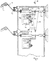
- FIG. 1 is a simplified partial elevational view of a portion of illustrative apparatus constructed according to the present invention, taken along the direction of the longitudinal axis of an armature to be gripped.
- FIG. 1 also shows a partial sectional view of the conveyor taken along the line 1'-1' in FIG. 2.
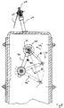
- FIG. 2 is an elevational view taken generally along the line 2-2 in FIG. 1 when the holders of the first transfer mechanism are rotated and with additional illustrative apparatus constructed according to this invention.
- FIG. 2 shows elements broken off in FIG. 1, albeit at a different scale and from a different direction.
- FIG. 2 also shows a partial elevational view of the conveyor.
- FIG. 3 is an isometric view of a portion of the apparatus shown in FIG. 2 with still more apparatus constructed according to the invention.
- FIG. 4 is a sectional view taken generally along the line 4-4 in FIG. 3 showing an illustrative embodiment of additional aspects of the invention.
- FIG. 5 is a sectional view taken along the line 5-5 in FIG. 4.
- the present invention relates to dynamo-electric machine parts manufacturing equipment which is capable of delivering and receiving dynamo-electric machine parts (such as armatures or stators for electric motors, generators, alternators, or the like) at the conveyor in a single alignment position, while simultaneously processing two or more previously received parts.
- dynamo-electric machine parts such as armatures or stators for electric motors, generators, alternators, or the like
- the invention will be illustrated in conjunction with an endless conveyor on which armatures are conveyed in seats, it will be understood that other types of parts (such as stators) and/or other types of conveyance (such as palletized conveyance) can be used instead if desired.
- FIG. 1 shows a sub-unit 10 of the transfer device pertaining to this invention positioned over a conveyor 11.
- the conveyor is required for transporting the armature cores (e.g., assembled armature shaft, commutator, and ferromagnetic core) which need to be wound to the multiple armature winder.
- the same conveyor 11 also transports the armatures wound by the multiple armature winder to a downstream station for further processing, e.g., a fusing operation.
- the unwound armature cores 12 to be transferred to the multiple armature winder for winding become centered by the conveyor on vertical axis 13'.
- an empty seat 9 of the conveyor is shown aligned on axis 13'. This seat is empty because an armature has already been removed for transfer to the multiple armature winder).
- Sub-unit 10 is provided with two grippers 10' and 10'' for grasping armatures around their core stack 12'.
- the grippers are shown grasping armatures and positioned on axis 13' over the conveyor.
- Grippers of this type are provided with index mechanisms which rotate the armature once they have grasped it. This index operation is required to locate in a predetermined angular position the commutator tangs and the stack slots of the armatures for winding and lead connection by the multiple armature winder.
- These grippers can be the same as those described in Andorlini et al. U.S. patent 5,253,912, which is hereby incorporated by reference herein. Therefore, their detailed structure and operating principles will be examined only in those aspects which are required to fulfill the description requirements of this invention.
- grippers 10' and 10'' are fixed to a common support plate 14.
- Each gripper has two movable jaws (10'a for gripper 10' and 10''a for gripper 10'') to grasp the most external circumferential surface of the stack 12'.
- the openings between the jaws when they are grasping a respective armature are centered on axis 13 (as shown in FIG. 2) or on axis 13' over the conveyor (as shown in FIG. 1).
- Support plate 14 has on its rearward side a cylindrical prolongation 14' supported on bearings 15 and 15' seated in an annular portion 16' of support arm 16. The free end of the cylindrical prolongation has flanged to it a gearwheel 17.
- This gearwheel meshes with a pinion 18 keyed to a shaft 19' of air cylinder 19.
- Air cylinder 19 is mounted on support arm 16.
- Shaft 19' is made to rotate for a certain angle in a clockwise 19a or anticlockwise 19b direction depending on which side of the air cylinder becomes supplied with air.
- gripper 10' moves to occupy the upper U position occupied by gripper 10'', and at the same time gripper 10'' will move to occupy the lower position L occupied by gripper 10'. After this exchange of positions, the center of the jaw openings when grasping the armatures will still be positioned on axis 13' over the conveyor.
- Support arm 16 extends upwardly toward a frame structure 21. At its upward end support arm 16 is bolted by means of nut 22 to an end of vertical shaft 23. This shaft is supported for vertical movement in either of directions 24' and 24'' by a guide unit 25.
- Vertical shaft 23 is connected at its upper end to the rod of air cylinder 32 by horizontal bracket 23'. By pressurizing the lower chamber of air cylinder 32, vertical shaft 23 will be moved upwardly in direction 24', while by pressurizing the upper chamber of air cylinder 32, vertical shaft 23 will be moved downwardly in direction 24''.
- shaft 23 rotates around axis 29 by having pulley wheel 26 flanged to a sleeve 31 extending from guide unit 25.
- pulley wheel 26 is connected to a drive pulley wheel 28 keyed to the shaft of air cylinder 27.
- Air cylinder 27 is fixed to frame structure 21.
- the connection between pulley wheels 26 and 28 is obtained by means of belt 30.
- the drive pulley wheel 28 will rotate for a certain angle, either in a clockwise or in an anticlockwise direction, depending on which side of air cylinder 27 is supplied with air.
- the rotation of shaft 23 around axis 29 will cause the support arm to do the same, which consequently moves the grippers between being positioned on axis 13 and on axis 13'.
- the grippers On axis 13, the grippers will be facing direction 30 (as they are shown in FIG. 2) to deliver the armatures they are grasping to another sub-unit 40 or to receive armatures from the same sub-unit if they are empty.
- the grippers On axis 13', the grippers will be facing direction 30' to deliver or to receive armatures carried by a seat of conveyor 11.
- the seat of conveyor 11 consists of two opposite V supports 9' and 9'', each hinged to a respective chain.
- An armature is carried in the seat by supporting the ends of shafts 12''' in these V supports.
- the gripper of sub-unit 10 in the lower position L must be empty and have its jaws open. Then support arm 16 can descend to bring the open jaws in a condition where the latter straddle around the stack 12' of the armature positioned in a conveyor seat which has been previously aligned on axis 13'. To cause this descent, air cylinder 32 becomes pressurized in its upper chamber so that vertical shaft 23 will move in direction 24'' along axis 29 for a predetermined path, which brings the jaws in position to grip the stack of the armature presented on axis 13' by the conveyor. Subsequently, the jaws can be closed to grip the stack, and soon thereafter the support arm can be raised by pressurizing air cylinder 32 in its lower chamber so that vertical shaft 23 will move in direction 24'.
- air cylinder 19 can be pressurized to rotate support plate 14 in order to bring the other gripper in the lower position L.
- Similar operations as those described previously can be performed to have this gripper receive an armature from another seat of the conveyor which becomes aligned on axis 13'.
- air cylinder 27 can be pressurized to cause rotation of support arm 16 so that the shafts of these armatures become aligned with respective grippers 41 and 42 (FIG. 3) of sub-unit 40 when sub-unit 10 reaches alignment on axis 13 as shown in FIG. 2.
- FIG. 2 shows an embodiment of sub-unit 10 which is able to receive from the conveyor armatures which have their commutator 12'' on the left side according to the view shown in FIG. 2.
- this orientation of the armatures requires the rotation around axis 29 by means of air cylinder 27 to orient the armatures properly for delivery to the winder. If the conveyor were to transport the armatures with the commutator on the right (opposite to the machine side of the conveyor), then the rotation around axis 29 would not be required.
- grippers 10' and 10'' would be permanently aligned on axis 13' and the alignment with the grippers of sub-unit 40 would be obtained by the position which support arm 16 reaches for the maximum upwards extension of air cylinder 32.
- FIG. 3 shows in greater detail sub-unit 40, which transfers armatures between sub-unit 10 and the multiple armature winder W.
- the chucks and the flyer assemblies of one side of the multiple armature winder are referenced 50 and 51, while those of the other side are not shown.
- the winding axes on which the armatures need to be positioned for winding by the multiple armature winder have been referenced 52 and 53.
- Grippers 41 and 42 (gripper 42 remains hidden in FIG. 3), parallel to each other for holding armatures to be wound, are mounted on slide 43, which is able to translate on guide 44 in directions 43' and 43'' by means of air cylinder 44'.
- Guide 44 is fixed to one side of support structure 45. By translating in direction 43' the slide moves toward a forward end of structure 45. The movement in direction 43' allows grippers 41 and 42 to receive armatures to be wound from grippers 10' and 10'' from sub-unit 10 or to deliver the same armatures to collets of the multiple winder positioned on winding axes 52 and 53.
- Translation in direction 43'' causes the slide to move to a rearward end of central structure 45. This translation is required to take the armatures to be wound away from grippers 10' and 10'' of sub-unit 10, or to retract grippers 41 and 42 away from the winder after the armatures to be wound have been delivered to the collets of the winder positioned on winding axes 52 and 53.
- Grippers 47 and 48 are mounted on slide 46, which is able to translate on guide 49 in directions 43' and 43'' by means of air cylinder 49'.
- Guide 49 is fixed to one side of support structure 45. By translating in direction 43' the slide moves toward a forward end of structure 45. This movement is required to deliver wound armatures held by grippers 47 and 48 to grippers 10' and 10'' of sub-unit 10, or to receive in grippers 47 and 48 wound armatures from the collets of the winder positioned on winding axes 52 and 53.
- Structure 45 can translate between two sideways positions because it is mounted on guides 51 of base 153. Air cylinder 152, connected to structure 45, can be used to cause this translation. Base 153 is supported for rotation around axis 54 by being mounted on bearing column 55. Air cylinder 56 has a pinion (not shown) which meshes with gearwheel (not shown) integral with base 53 to obtain this rotation around axis 54.
- base 153 By supplying pressurized air alternatively to the two chambers of air cylinder 56, base 153 is rotated around axis 54, either in a clockwise or anticlockwise direction, depending on which chamber is supplied. This causes grippers 41, 42, 47, and 48 to move between a position where the grippers face the multiple winder and a position where they are facing sub-unit 10.
- a start condition for this description can be the situation where grippers 47 and 48 are in the forward position (as shown in FIG. 3), ready to remove wound armatures from the winder.
- unwound armatures delivered by grippers 10' and 10'' are held by grippers 41 and 42.
- structure 45 translates in direction 60' by means of air cylinder 52 to align grippers 41 and 42 with the winder axes 52 and 53.
- slide 43 can be moved forward in direction 43' by means of air cylinder 44 to allow the collets of the winders to receive the unwound armatures from grippers 41 and 42.
- grippers 41 and 42 Once grippers 41 and 42 have delivered these armatures and retracted from the winder, the winder can start winding again, and base 153 can be rotated by means of air cylinder 56 for 180° around axis 54 to make the grippers face sub-unit 10. At the end of this rotation, grippers 41 and 42 (which are empty) will be aligned with grippers 10' and 10'' of sub-unit 10 (which will be positioned on axis 13) and holding unwound armatures ready to be delivered. Then grippers 41 and 42 can move forward to receive the unwound armatures, and immediately after this they can retract to their backward position by inverting the supply of air cylinder 44'.
- structure 45 will move sideways in direction 60' to align grippers 47 and 48 with grippers 10' and 10'' so that the former can move forward to deliver the wound armatures.
- support arm 16 will rotate around axis 29 to bring grippers 10' and 10'' on axis 13' over the conveyor.
- base 153 will rotate around axis 54 to align empty grippers 46 and 47 with the winding axes of the winder.
- grippers 47 and 48 will wait until the winder has finished winding, and only then will these grippers move forward to receive the wound armatures to be transferred back to sub-unit 10 in the same way that has been described previously.
- Support arm 16 descends to allow the gripper of the lower position L to deposit a wound armature in the waiting empty seat of the conveyor. Then, support arm 16 is raised to allow this empty gripper to clear the conveyor by the upward motion of support arm 16. Once this has occurred, a new seat of the conveyor with an unwound armature is positioned in alignment on axis 13'. Then, support arm 16 descends again to allow the empty gripper to pick up an unwound armature, which has just been presented by the new seat of the conveyor.
- the grippers of sub-unit 10 exchange their positions by rotating around axis 20 through the activation of air cylinder 19. This will bring the gripper that was in the upper position with a wound armature to lower position L and the gripper with the unwound armature to the upper position U. In this situation, the gripper which is now in the lower position can descend to deposit the wound armature in the seat which had brought the unwound armature now being held by gripper in the upper position.
- sub-unit 10 which does not have the rotation possibility around axis 29 and therefore interfaces with a conveyor that transports the armatures with the commutator on the right side, support arm only moves up and down in directions 24' and 24'' to pick up or deliver the armatures and to align them with grippers 41 and 42 of sub-unit 40.
- the transfer solution consisting of the combination of sub-unit 10 and sub-unit 40 makes it possible to transfer armatures between seats of the conveyor which become positioned in a single load/unload position (in alignment with axis 13') and the multiple armature winder.
- This allows a step-by-step advancement conveyor like the one described previously to be used to feed armatures both to a multiple armature winder and to a further processing machine such as a fusing machine which also receives and delivers armatures via seats of the conveyor that become positioned in a single downstream load/unload position.
- a fusing machine which also receives and delivers armatures via seats of the conveyor that become positioned in a single downstream load/unload position.
- step-by-step advancement of the conveyor to present the unwound armatures to sub-unit 10 of the multiple armature winder will present at the same time armatures to be fused to a transfer device of the fusing machine situated downstream, and take away wound armatures delivered by sub-unit 10 and fused armatures delivered by the transfer device of the fusing machine.
- the criterion for advancement of the conveyor needs to be that it should advance by a step only when both the seat at the winding machine and the seat at the fusing machine have received a processed armature. Furthermore, the machines should be kept in operation for as long as possible and have to wait the least possible inoperative time for receiving armatures with their transfer devices. Thus, the transfer devices need to be extremely rapid in receiving and delivering armatures with the machines, and they must have a preparation period for being ready to do so which is short enough and set to occur when the machines are operating.
- the two advancements of the conveyor described previously to receive and deliver armatures by means of sub-unit 10 for one operating cycle of the multiple armature winder will coincide with loading and unloading required for two operating cycles of a fusing machine which fuses one armature at a time.
- the multiple winder will be inoperative only for the time which sub-unit 40 is required to move forward and rearward grippers 41, 42, 47, and 48, as has been described above for loading and unloading armatures in front of the winder by sub-unit 40, and for the time to exchange these grippers in front of the winder by translating structure 45 in direction 60'.
- the rotation of base 153 to transfer armatures between sub-unit 10 and the winder occurs when the latter is winding.
- Even the operations of sub-unit 10 to deliver and receive armatures with the seats of the conveyor and the advancements of these seats will occur when the winder is operating.
- the related transfer unit will need to keep the inoperative time as short as possible and also guarantee that the time it will take to exchange armatures with the conveyor will have to be equal to or less than the time which is required to carry out similar operations with the grippers of sub-unit 10. This makes it possible to have synchronization between the operations of the transfer devices of the two machines.
- the advantage of transferring armatures between seats of the conveyor aligned with a single position and the multiple armature winder is also useful when the conveyor is of a type having pallets carrying more than one armature at the same time.
- the distance between adjacent armatures may be such that there is not sufficient room to allow two adjacent pick-up grippers (like those of the Santandrea et al. '052 patent) to operate.
- sub-unit 10 can be used successfully with operations similar to those described previously, to load and unload them.
- a one-step advancement of the conveyor described previously will correspond to an advancement of the pallet which brings a new seat (the second seat) of the same pallet in alignment with sub-unit 10, or the advancement of another pallet to align its first seat because the previous pallet has been completely loaded and unloaded.
- FIGS. 4 and 5 relate to the portion of this disclosure which presents improved operating principles of the multiple armature winder to increase its productivity.
- these principles are particularly useful for multiple armature winders which have rotation of two flyers on a same side of the multiple armature winder driven by a common motor.
- Each of these flyers winds one-half of the coils of a respective armature which it is winding.
- the two flyers on the other side of the multiple armature winder will have another common motor to drive their rotation.
- Each of these flyers will wind the other half of the respective armature which it is winding.
- To use this common motor for rotating the two flyers instead of one motor for each flyer, reduces the cost of the motorization of the multiple armature winder. However, it may cause inconvenience when the wire breaks in one of the flyers.
- This invention provides a solution which reduces the amount of production which is lost due to a wire breakage, and makes it simpler and faster for the operator to restore the multiple armature winder after such a breakage.
- a detection unit can detect the breakage of any of the four wires going to their respective flyers. Once this unit signals the breakage, a device intervenes to instantaneously control the broken wire (e.g., by withdrawing that wire relative to the flyer) so that it will not be further dispensed by centrifugal forces. This control of the broken wire occurs while the flyers are rotating and results in a situation where the flyers without broken wires will continue to wind the coils which had been started before the breakage of the wire.
- the flyer opposite to the one where the wire has been withdrawn carries out traditional termination operations by means of flyer rotations to connect the lead of the last wound coil to the commutator.
- the wire is then cut between the flyer and the commutator, and the cut wire is promptly controlled (e.g., by withdrawing it relative to the flyer).
- the cut wire may be initially gripped in the conventional manner, but this grip is released in order to permit withdrawal of the wire.
- the armature where the wire has not broken also undergoes lead connection of the last wound coils to the commutator because a common drive exists between the opposite flyers.
- the wires are only connected to the commutator without carrying out the successive cutting and gripping operations (unless, of course, the last-wound coils are the final coils to be wound on the armature).
- each flyer of the winder has its own independently driven cutter and gripping device.
- the flyer where the broken wire has been withdrawn will continue to rotate due to the common drive.
- both flyers for the armature where the breakage occurred are able to rotate without the danger of dispensing wire in an uncontrolled way.
- the flyers for continuing to wind coils of the armature where the wire has not been broken may continue to do so by means of the common drives until all the coils are completed.
- the armature Once the armature is completed, it can be removed from the winder and substituted with another unwound armature so that the multiple armature winder can continue to produce, even if it will only be doing so at half of its normal production capability.
- FIGS. 4 and 5 show illustrative devices for withdrawing the wires from the flyer.
- wire 70 for winding coils of an armature passes from a dancer arm 71 which is part of a traditional tensioner device.
- Each flyer has a respective tensioner device for keeping the wire it is dispensing at the required tension for winding.
- the wire travels through wheel 72 which aligns the wire with a horizontal tube 73 through which it passes so that it can reach the rear end of flyer shaft 74.
- the wire is threaded through a passing ring 75 which is part of withdrawal arm 76.
- the wire runs through the entire length of the flyer shaft to reach the outwardly extending arm 77 of the flyer and then the extreme dispensing pulley 78 from which it is dispensed to wind the armature coils.
- the flyer shaft, together with the extending arm, is rotated to achieve winding by the common motor described previously.
- Withdrawal arm 76 is fixed by nut 78 to the shaft of rotation cylinder 79. By feeding pressurized air to cylinder 79, withdrawal arm 76 can be rotated for a certain angle in direction 79' and 79'', depending on which side of air cylinder 79 is supplied (see FIG. 5).
- the withdrawal arm When winding the armature coils by means of the flyer, the withdrawal arm will be in a normal operation position represented by full line representation 76 shown in FIGS. 4 and 5. In this position passing ring 75 is aligned with tube 73 and with the rear end of flyer shaft 74. Furthermore, cylinder 79 will be pressurized on a side which would rotate withdrawal arm in direction 79'. To impede this rotation during normal winding, pin 80 is used as an abutment for the arm. When breakage of the wire is detected, the related signal causes this pin to be retracted in horizontal direction 81 so that it moves out of the way to allow the withdrawal arm to rotate in direction 79' as shown by the two phantom representations 76' and 76'' of FIG. 5.
- Representation 76'' shows the position reached by the arm at the end of this rotation.
- wire 70 can not leave passing ring 75. Therefore, the stretch of wire going to the flyer is drawn rearwardly so that it becomes removed at least from extending arm 77, which continues rotating at winding speed.
- This removal of wire corresponds to extra wire extension 82 shown in phantom representation in FIGS. 4 and 5.
- the rotation of the withdrawal arm to remove the wire must occur rapidly. Otherwise the high-speed rotation of the extending arm will be able to draw further wire by means of the centrifugal forces. For this reason, cylinder 79 is already pressurized to make the withdrawal arm rotate in direction 79' quickly, thus avoiding delays to correctly pressurize the required chamber of cylinder 79.
- Pin 80 can be extremely rapid in moving out of the way if it is caused to do so by an electromagnetic translation drive.
- the device which detects the breakage of the wire is well known and commonly used in the prior art to command flyer rotation when a wire breakage occurs during winding. Usually this device detects the breakage by measuring an abnormal oscillation of the dancer arm or a sudden variation of the wire travel due to the wire breakage.
- the portion without numbering in FIG. 4 shows another withdrawal device applied to a lower flyer which is driven by the same motor which rotates flyer shaft 74.
- flyers on the other side of the multiple armature winder will be provided with withdrawal devices like those shown in FIGS. 4 and 5, so that for each wire being wound, breakage can be detected and consequent withdrawal can occur.
- FIGS. 4 and 5 are equally applicable to multiple armature winders in which separate motors are used for each winder.
Landscapes
- Engineering & Computer Science (AREA)
- Manufacturing & Machinery (AREA)
- Power Engineering (AREA)
- Manufacture Of Motors, Generators (AREA)
Applications Claiming Priority (5)
| Application Number | Priority Date | Filing Date | Title |
|---|---|---|---|
| US1672596P | 1996-05-03 | 1996-05-03 | |
| US16725 | 1996-05-03 | ||
| US695835 | 1996-08-07 | ||
| US08/695,835 US5799896A (en) | 1996-05-03 | 1996-08-07 | Multiple dynamo-electric machine parts handling and winding methods and apparatus |
| 2001-02-02 |
Publications (2)
| Publication Number | Publication Date |
|---|---|
| EP0741442A2 true EP0741442A2 (de) | 1996-11-06 |
| EP0741442A3 EP0741442A3 (de) | 1998-10-28 |
Family
ID=26688992
Family Applications (1)
| Application Number | Title | Priority Date | Filing Date |
|---|---|---|---|
| EP96113062A Withdrawn EP0741442A3 (de) | 1996-05-03 | 1996-08-14 | Verfahren und Vorrichtung zur Handhabung und zum Aufwickeln von mehreren Teilen einer dynomoelektrischen Maschine |
Country Status (3)
| Country | Link |
|---|---|
| US (2) | US5799896A (de) |
| EP (1) | EP0741442A3 (de) |
| CA (1) | CA2203350A1 (de) |
Cited By (2)
| Publication number | Priority date | Publication date | Assignee | Title |
|---|---|---|---|---|
| EP0892483A3 (de) * | 1997-07-16 | 2000-07-19 | AXIS S.p.A. | Verfahren und System zur Handhabung von Drahtbruch und Überlauf bei einer multiplen Wickelmaschine für Bauteile einer Dynamoelektrischemaschine |
| EP0963030A3 (de) * | 1998-06-02 | 2000-08-30 | Otto Rist | Vorrichtung zum Wickeln von Spulen |
Families Citing this family (5)
| Publication number | Priority date | Publication date | Assignee | Title |
|---|---|---|---|---|
| US5799896A (en) * | 1996-05-03 | 1998-09-01 | Axis Usa, Inc. | Multiple dynamo-electric machine parts handling and winding methods and apparatus |
| US6127652A (en) * | 1997-02-14 | 2000-10-03 | Axis Usa, Inc. | Wire changing in an armature winder |
| US6070826A (en) * | 1997-09-25 | 2000-06-06 | Axis Usa, Inc. | Armature winder shroud changing apparatuses and methods |
| US6612519B1 (en) * | 1999-11-02 | 2003-09-02 | Axis Usa, Inc. | Methods and apparatus for winding electric machine cores |
| ITPI20130031A1 (it) * | 2013-04-19 | 2014-10-20 | Atop Spa | Linee di produzione per produrre componenti di nucleo di una macchina dinamo-elettrica |
Family Cites Families (12)
| Publication number | Priority date | Publication date | Assignee | Title |
|---|---|---|---|---|
| US4087054A (en) * | 1977-02-08 | 1978-05-02 | The Globe Tool And Engineering Company | Armature transfer mechanism for armature winders |
| IT1186909B (it) * | 1985-07-17 | 1987-12-16 | M P Spa Sa | Robot programmabile per l alimentazione e lo scarico rispettivamente delle bobine vuote e delle bobine piene in e da macchine bobinatrici |
| IT1215177B (it) * | 1986-08-04 | 1990-01-31 | Magneti Marelli Spa | Macchina automatica per la formazione degli avvolgimenti di indotto nelle cave di rotori di macchine dinamoelettriche |
| JPH0697824B2 (ja) * | 1989-03-22 | 1994-11-30 | 株式会社三ツ葉電機製作所 | コンミテータ用ヒュージング装置 |
| JP2716786B2 (ja) * | 1989-03-22 | 1998-02-18 | 株式会社ミツバ | モータ回転子の巻線状態検出装置 |
| US5372319A (en) * | 1989-10-03 | 1994-12-13 | Globe Products Inc. | Apparatus for loading and unloading workpieces |
| US5257689A (en) * | 1991-04-10 | 1993-11-02 | Axis Usa, Inc. | Apparatus for substantially simultaneously processing multiple electric motor parts |
| US5145052A (en) * | 1991-04-10 | 1992-09-08 | Axis Usa, Inc. | Apparatus for substantially simultaneously processing multiple electric motor parts |
| US5253912A (en) * | 1991-04-10 | 1993-10-19 | Axis Usa, Inc. | Gripper apparatus for electric motor components |
| US5680696A (en) * | 1994-09-13 | 1997-10-28 | Axis Usa, Inc. | Dynamo-electric machine component conveying systems with load/unload devices |
| US5653014A (en) * | 1994-09-13 | 1997-08-05 | Axis Usa, Inc. | Dynamo-electric machine component conveying systems and load/unload devices |
| US5799896A (en) * | 1996-05-03 | 1998-09-01 | Axis Usa, Inc. | Multiple dynamo-electric machine parts handling and winding methods and apparatus |
-
1996
- 1996-08-07 US US08/695,835 patent/US5799896A/en not_active Expired - Fee Related
- 1996-08-14 EP EP96113062A patent/EP0741442A3/de not_active Withdrawn
-
1997
- 1997-04-22 CA CA002203350A patent/CA2203350A1/en not_active Abandoned
-
1998
- 1998-07-08 US US09/112,180 patent/US6012670A/en not_active Expired - Fee Related
Cited By (3)
| Publication number | Priority date | Publication date | Assignee | Title |
|---|---|---|---|---|
| EP0892483A3 (de) * | 1997-07-16 | 2000-07-19 | AXIS S.p.A. | Verfahren und System zur Handhabung von Drahtbruch und Überlauf bei einer multiplen Wickelmaschine für Bauteile einer Dynamoelektrischemaschine |
| EP0963030A3 (de) * | 1998-06-02 | 2000-08-30 | Otto Rist | Vorrichtung zum Wickeln von Spulen |
| US6283169B1 (en) | 1998-06-02 | 2001-09-04 | Otto Rist | Apparatus for the winding of coils |
Also Published As
| Publication number | Publication date |
|---|---|
| CA2203350A1 (en) | 1997-11-03 |
| EP0741442A3 (de) | 1998-10-28 |
| US6012670A (en) | 2000-01-11 |
| US5799896A (en) | 1998-09-01 |
Similar Documents
| Publication | Publication Date | Title |
|---|---|---|
| JPS6356153B2 (de) | ||
| CZ283034B6 (cs) | Způsob a zařízení k zásobování navíjecích ústrojí textilního stroje prázdnými dutinkami | |
| JPH0748734A (ja) | ポット精紡機用の搬送系 | |
| US5109662A (en) | Operating method and apparatus for the automated removal of yarn remnants from winding tubes by an automated maintenance and servicing device traveling along a textile yarn processing machine | |
| US5145052A (en) | Apparatus for substantially simultaneously processing multiple electric motor parts | |
| US5680696A (en) | Dynamo-electric machine component conveying systems with load/unload devices | |
| US5799896A (en) | Multiple dynamo-electric machine parts handling and winding methods and apparatus | |
| EP0026160B1 (de) | Verfahren zur aufwicklung und montage von spulen und vorrichtung zur ausführung des verfahrens | |
| EP0490173B1 (de) | Maschine zum Wickeln von Statoren | |
| HU210119B (en) | Double-twist twisting machine for producing twisted articles | |
| EP0285186B1 (de) | Vorrichtung und Verfahren zum automatischen Spulenwechsel an einer Aufwickelmaschine | |
| JPS5971430A (ja) | オープンエンド精紡機における糸継ぎ及び糸パッケージの玉揚げのための改善された装置 | |
| EP0256997A1 (de) | Automatische Maschine für die Entstehung von Ankerwicklungen in Läufernuten dynamoelektrischer Maschinen | |
| EP0559041B1 (de) | Verfahren und Vorrichtung zum Behandeln des Spulenfadenendes | |
| JP2000224819A (ja) | 巻線装置 | |
| US4174815A (en) | Apparatus for winding armatures | |
| US6213422B1 (en) | Method and system for handling wire breakage and overflow in a multiple dynamo-electric machine part winder | |
| US5207051A (en) | Apparatus for transferring full bobbins and empty bobbins between a bobbin winding machine and a transporting mechanism | |
| US5010724A (en) | Method and apparatus for producing packages | |
| JP2000327227A (ja) | パッケージ交換の際に供給される糸を案内しかつ切断する装置及び方法 | |
| US5149000A (en) | Machine for winding two-pole stators | |
| CZ283781B6 (cs) | Způsob a zařízení pro předávání jednotlivých cívek nebo skupin cívek z textilního stroje na dopravní ústrojí cívek a prázdných cívek z dopravního ústrojí na textilní stroj | |
| EP0721909A1 (de) | Vorrichtung zur kontrollierten Spulpositionierung in einer Station einer automatischen Wickelmaschine für konische Spulen | |
| US5329756A (en) | Automatic device for starting a two-for-one twisting station after interruption of the feed yarn and relative automatic process | |
| US5343687A (en) | Winder-to-double twister connecting system |
Legal Events
| Date | Code | Title | Description |
|---|---|---|---|
| PUAI | Public reference made under article 153(3) epc to a published international application that has entered the european phase |
Free format text: ORIGINAL CODE: 0009012 |
|
| AK | Designated contracting states |
Kind code of ref document: A2 Designated state(s): CH DE ES FR GB IT LI NL SE |
|
| ITCL | It: translation for ep claims filed |
Representative=s name: BARZANO'E ZANARDO S.P.A. |
|
| PUAL | Search report despatched |
Free format text: ORIGINAL CODE: 0009013 |
|
| AK | Designated contracting states |
Kind code of ref document: A3 Designated state(s): CH DE ES FR GB IT LI NL SE |
|
| 17P | Request for examination filed |
Effective date: 19990428 |
|
| STAA | Information on the status of an ep patent application or granted ep patent |
Free format text: STATUS: THE APPLICATION IS DEEMED TO BE WITHDRAWN |
|
| 18D | Application deemed to be withdrawn |
Effective date: 20030311 |