EP0741499A2 - Non-blocking optical cross-connect structure for telecommunications network - Google Patents
Non-blocking optical cross-connect structure for telecommunications network Download PDFInfo
- Publication number
- EP0741499A2 EP0741499A2 EP96302073A EP96302073A EP0741499A2 EP 0741499 A2 EP0741499 A2 EP 0741499A2 EP 96302073 A EP96302073 A EP 96302073A EP 96302073 A EP96302073 A EP 96302073A EP 0741499 A2 EP0741499 A2 EP 0741499A2
- Authority
- EP
- European Patent Office
- Prior art keywords
- wavelength
- wavelengths
- reordering
- converting
- order
- Prior art date
- Legal status (The legal status is an assumption and is not a legal conclusion. Google has not performed a legal analysis and makes no representation as to the accuracy of the status listed.)
- Withdrawn
Links
- 230000003287 optical effect Effects 0.000 title claims abstract description 57
- 230000000903 blocking effect Effects 0.000 claims abstract description 23
- 238000003491 array Methods 0.000 claims description 27
- 239000000835 fiber Substances 0.000 abstract description 52
- 239000013307 optical fiber Substances 0.000 description 12
- 238000010586 diagram Methods 0.000 description 7
- 230000005540 biological transmission Effects 0.000 description 6
- 230000008901 benefit Effects 0.000 description 3
- 238000010276 construction Methods 0.000 description 3
- 230000005855 radiation Effects 0.000 description 2
- 229910003327 LiNbO3 Inorganic materials 0.000 description 1
- 238000004891 communication Methods 0.000 description 1
- 239000011159 matrix material Substances 0.000 description 1
- 238000000034 method Methods 0.000 description 1
- 230000008929 regeneration Effects 0.000 description 1
- 238000011069 regeneration method Methods 0.000 description 1
- 238000006467 substitution reaction Methods 0.000 description 1
- 230000009466 transformation Effects 0.000 description 1
- 238000000844 transformation Methods 0.000 description 1
- 230000001131 transforming effect Effects 0.000 description 1
Images


Classifications
-
- H—ELECTRICITY
- H04—ELECTRIC COMMUNICATION TECHNIQUE
- H04Q—SELECTING
- H04Q11/00—Selecting arrangements for multiplex systems
- H04Q11/0001—Selecting arrangements for multiplex systems using optical switching
- H04Q11/0005—Switch and router aspects
-
- H—ELECTRICITY
- H04—ELECTRIC COMMUNICATION TECHNIQUE
- H04Q—SELECTING
- H04Q11/00—Selecting arrangements for multiplex systems
- H04Q11/0001—Selecting arrangements for multiplex systems using optical switching
- H04Q11/0005—Switch and router aspects
- H04Q2011/0007—Construction
- H04Q2011/0009—Construction using wavelength filters
-
- H—ELECTRICITY
- H04—ELECTRIC COMMUNICATION TECHNIQUE
- H04Q—SELECTING
- H04Q11/00—Selecting arrangements for multiplex systems
- H04Q11/0001—Selecting arrangements for multiplex systems using optical switching
- H04Q11/0005—Switch and router aspects
- H04Q2011/0007—Construction
- H04Q2011/0011—Construction using wavelength conversion
-
- H—ELECTRICITY
- H04—ELECTRIC COMMUNICATION TECHNIQUE
- H04Q—SELECTING
- H04Q11/00—Selecting arrangements for multiplex systems
- H04Q11/0001—Selecting arrangements for multiplex systems using optical switching
- H04Q11/0005—Switch and router aspects
- H04Q2011/0007—Construction
- H04Q2011/0015—Construction using splitting combining
-
- H—ELECTRICITY
- H04—ELECTRIC COMMUNICATION TECHNIQUE
- H04Q—SELECTING
- H04Q11/00—Selecting arrangements for multiplex systems
- H04Q11/0001—Selecting arrangements for multiplex systems using optical switching
- H04Q11/0005—Switch and router aspects
- H04Q2011/0052—Interconnection of switches
Definitions
- This invention relates to an optical fiber transmission network and more specifically to an optical cross-connect switch for use in establishing high speed interconnections among the nodes of an all-optical network.
- Present day commercial lightwave transmission networks use optical fibers to carry large amounts of multiplexed information over long distances from a transmit terminal to a receive terminal.
- Most long-haul transmission lines and a substantial portion of short-haul transmission lines such as inter-office and intra-office links, local area networks (LANs), metropolitan area networks (MANs), and wide area network (WANs) are optical and, therefore, the information is carried over an optical fiber.
- LANs local area networks
- MANs metropolitan area networks
- WANs wide area network
- a major advantage of transmitting information in optical form is the very large bandwidth and low losses associated with single mode optical fibers.
- space-division switching networks are frequently designed to include a plurality of stages of switching nodes.
- the node stages are successively interconnected using a specified interconnection pattern.
- the individual switching nodes are typically selective in that they can connect any one of a plurality of node inputs to any one of a plurality of node outputs in response to control signals defining the desired connections.
- a necessary component for selectively interconnecting the nodes of a communication network in this manner is a high capacity matrix or cross-connect switch.
- multiplexed optical signals are supplied from input optical fibers 1 through M.
- Each optical channel is separated to respective wavelengths ⁇ 1 through ⁇ N by a corresponding one of the wavelength demultiplexers.
- the demultiplexed wavelengths enter the MN x MN cross connect structure 410 and are directed, via an optical frequency converter and a wavelength demultiplexer, to appropriate output fibers 1 through M for transmission to a destination node.
- cross-connect structure 410 is non-blocking in that any idle inlet is always connectable to any idle outlet regardless of other array interconnections, the enormous size, design complexity, and large number of interconnections required for such a structure make it extremely expensive to fabricate and thus unsuitable for commercial applications.
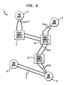
- the present invention provides an all-optical network utilizing, as intermediate nodes, non-blocking optical cross connect structures interconnected by fiber links.
- Each cross connect structure is capable of spatially and independently exchanging optical channels or signals of different wavelengths with one or more network end-nodes and/or with additional cross-connect structures. As such, connections may be established in a non-blocking manner between any input channel on any input fiber coupled to the cross connect and any output channel available on any output fiber coupled to the cross-connect.
- the modular construction of the cross connect structures of the present invention are much less complex than a single MN x MN cross connect structure and are thus significantly less expensive to design and fabricate.
- Each cross-connect is capable of receiving, from each of M multiplexed wavelength paths defined by a corresponding number of input fibers, an optical signal comprising up to N distinct channels or wavelengths.
- Each of the received wavelengths may be modulated with information to be transmitted through the cross-connect to an end-node, either directly or via one or more additional cross-connect nodes of the network. Since multiple wavelengths may be used on each input and output fiber coupled to the respective cross-connect structures, multiple simultaneous wavelength paths may be established between the end and intermediate nodes of the network to provide enhanced routing flexibility.
- the optical signals can flow between users across the network without being converted to electronic signals, the network has a very wideband width and data carried by the network is unimpeded by optical-to-electronic transformations.
- all of the wavelengths are spatially grouped according to fiber of origin after wavelength demultiplexing.
- the wavelengths are then rearranged in accordance with their respective destination nodes. Wavelengths to be transmitted to the same destination are multiplexed together and transmitted to the appropriate destination by way of an optical fiber link. In this way, high throughputs are established among the network nodes.
- a non-blocking cross-connect structure constructed in accordance with the present invention comprises wavelength division demultiplexing means for receiving multiple wavelength channels from each source fiber and for separating received channels into N wavelengths so that the wavelengths are organized according to a corresponding fiber of origin, each individual wavelength from each source fiber being capable of carrying information destined for one specific destination fiber.
- the cross-connect structure further includes nonblocking optical means for rearranging the received wavelengths so that wavelengths having a common destination waveguide are grouped together, and wavelength division multiplexing means for multiplexing together grouped wavelengths having the same destination fiber.
- the nonblocking optical means includes first spatial switching means having a plurality of inputs for receiving each demultiplexed wavelength from the wavelength division demultiplexing means and a plurality of outputs.
- the first spatial switching means is operative to supply any of the demultiplexed wavelengths to any of the outputs.
- the optical means further includes order preserving, wavelength changing means for receiving each demultiplexed wavelength from the outputs of the first spatial switching means and for changing or converting any received wavelength carrying information destined for a specific destination fiber to a wavelength currently available on the specific destination fiber, and second spatial switching means for receiving each converted wavelength from the wavelength changing means and for grouping the converted wavelengths according to destination fiber.
- each of the first and second spatial switching means includes N arrays of M X M optical switches.
- each of the first and second spatial switching means includes N arrays of M X 2M or M X (2M-1) optical switches.
- Each end node of network 1 comprises, by way of illustrative example, a transmitting system and a receiving system (neither of which are shown).
- Each transmitting system includes a plurality of output ports for outputting a plurality of low bit rate channels in electronic form.
- the channels are grouped according to destination -- that is, all of the channels to be transmitted to the same end node are grouped together.
- Each fiber trunk has a multiplicity of transmitted channels and includes a transmitting fiber and a receiving fiber.
- In each fiber there are multiple wavelengths or channels. Up to N distinct wavelengths are produced by each transmitting system, with each respective wavelength carrying information destined for a corresponding receiving system.
- each individual wavelength from each source fiber is capable of carrying information destined for one specific destination fiber.
- FIG. 3 there is illustrated a non-blocking cross-connect structure 10 constructed in accordance with an illustrative embodiment of the present invention and which may be used in an optical network such as the one depicted in FIG. 2.
- ⁇ 1 , ⁇ 2 , ... ⁇ N are carried in multiplexed form by each of a plurality of source waveguides, -- illustratively, input optical fibers 1 to M.
- non-blocking cross-connect structure 10 includes wavelength division demultiplexing means, in the form of an array of 1 X N wavelength division demultiplexers 12a to 12M, for receiving multiple wavelength radiation from each of the source fibers and for separating the received radiation into N wavelengths so that the wavelengths are organized according to a corresponding source or input fiber, nonblocking optical means 14 for rearranging the wavelengths so that wavelengths having a common destination or output fiber are grouped together, and wavelength division multiplexing means, in the form of an array of N X 1 wavelength division multiplexers 16a to 16M, for multiplexing together wavelengths having the same destination fiber.
- wavelength division demultiplexing means in the form of an array of 1 X N wavelength division demultiplexers 12a to 12M, for receiving multiple wavelength radiation from each of the source fibers and for separating the received radiation into N wavelengths so that the wavelengths are organized according to a corresponding source or input fiber
- nonblocking optical means 14 for rearranging the wavelengths so that wavelengths having a common destination or output fiber
- nonblocking optical means 14 includes first spatial switching means 18 for receiving each demultiplexed wavelength from demultiplexers 12a to 12M, order preserving wavelength changing means 20 for receiving each demultiplexed wavelength from first spatial switching means 18 and for converting any received wavelength carrying information destined for a specific destination fiber to a wavelength currently available on that specific destination fiber, and second spatial switching means 22 for receiving each converted wavelength from the wavelength changing means and for grouping the converted wavelengths according to destination fiber.
- FIGS. 4A-4E there are shown various order preserving, wavelength changing array configurations which may be employed as wavelength changing means 20 for converting or transforming signals on wavelengths having an order ⁇ 1 , ⁇ 2 ... ⁇ N into a different order, for example, ⁇ N , ⁇ 1 ... ⁇ 2 , in accordance with the present invention.
- FIG. 4A for example, there is shown a configuration of a wavelength changing array 30 which employs N variable-output wavelength changers 32a to 32N.
- Array 30 converts the respective input wavelengths in accordance with the availability of the wavelengths on corresponding destination fibers.
- a nonblocking N X N switch 34 reorders the converted wavelengths, thereby preserving the original order.
- the wavelength changing array 40 of FIG. 4B is similar to that of FIG. 4A except that the N X N switch is replaced by an N X N star coupler 42 and an array of fixed filters 44a to 44N.
- Another configuration of a wavelength changing array 50 is shown in FIG. 4C.
- Array 50 employs N variable-wavelength changers 52a to 52N, followed by an N X 1 star combiner 54 and a fixed 1 X N wavelength demultiplexer 56.
- FIG. 4D the configuration of FIG. 4A may be rearranged by placing the N X N switch 34 ahead of the wavelength changers 32a to 32N.
- This modified construction permits the use of fixed-output wavelength changers.
- FIG. 4E the elements of FIG. 4B may be rearranged to obviate the need for variable-output wavelength chambers.
- the outputs of N X N star coupler 42 are coupled to variable-output filters 44a to 44N, the outputs of which are, in turn, coupled to fixed-output wavelength changers 46a to 46N.
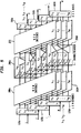
- a nonblocking optical cross-connect structure in accordance with the invention includes optical means for rearranging the wavelengths so that wavelengths having a common destination fiber are grouped together.
- the optical means includes first spatial switching means in the form of N arrays of M X M spatial switches 180a to 180N, order-preserving wavelength changing arrays 200a to 200M, and second spatial switching means in the form of N arrays of M X M spatial switches 220a to 220N.
- Spatial switches 180a to 180M each include a plurality of inputs for receiving each demultiplexed wavelength from the wavelength division demultiplexers and a plurality of outputs and are operative to supply any of the demultiplexed wavelengths to any of the outputs.
- spatial switching arrays 180 to 180N may be implemented with conventional LiNbO 3 switching devices.
- wavelength changing arrays 200a to 200N correspond to the configuration depicted in FIG. 4A, it will be readily appreciated that other order preserving, wavelength changing structures, such, for example, as those depicted in FIGS. 4B-4E, may also be employed.
- wavelength changing arrays 200a to 200M are configured to receive the demultiplexed wavelength from the outputs of the spatial switches and to convert any received wavelength carrying information destined for a specific destination fiber to a wavelength currently available on that destination fiber.
- Second spatial switches 220a to 220N then receive the converted wavelengths from the wavelength changing arrays and group the converted wavelengths according to destination fiber.
- a modified optical means includes first spatial switching means in the form of N arrays of M X 2M spatial switches 180a' to 180N', 2M order-preserving wavelength changing arrays 200a'to 200 2M ', and second spatial switching means in the form of N arrays of 2M X M spatial switches 220a' to 220N'.
- FIG. 7A utilizes the order preserving, wavelength changing array depicted in FIG. 4A.
- wavelengths ⁇ 1 , ⁇ 2 ... ⁇ N are supplied via source fiber 60 to a wavelength demultiplexer 62, converted into a second order of wavelengths, such as for example, ⁇ N , ⁇ 1 ... ⁇ 2 , by variable wavelength changers 64a to 64N in accordance with available wavelengths on the destination fiber 69, and reordered by N X N switch 66.
- the resulting ordered set of wavelengths are multiplexed by wavelength multiplexer 68 and supplied to output fiber 69.
- FIG. 7B A slightly modified embodiment of the arrangement of FIG. 7A is depicted in FIG. 7B.
- the N x N switch 66 and wavelength multiplexer 68 are replaced with an N x 1 star combiner 67.
- the output of the combiner 67 is supplied to fiber 69 as in the previous embodiment.
- the single fiber, wavelength division switch configuration of FIG. 7C utilizes the order preserving, wavelength changing array depicted in FIG. 4D.
- wavelengths ⁇ 1 , ⁇ 2 ,... ⁇ N are supplied via source fiber 70 to a wavelength demultiplexer 72 and reordered by N X N switch 74 as ⁇ 2 , ⁇ N ... ⁇ 1 .
- the wavelengths are then converted by variable wavelength changers 76a to 76N and the original order ⁇ 1 , ⁇ 2 ,... ⁇ N is thereby reestablished.
- the resulting ordered set of wavelengths are multiplexed by wavelength multiplexer 78 and supplied to destination fiber 79.
- the single fiber, wavelength division switch configuration of FIG. 7D utilizes the order preserving, wavelength changing array depicted in FIG. 4E.
- wavelengths in the illustrative order ⁇ 1 , ⁇ 2 ,... ⁇ N are supplied via source fiber 80 to a 1/N star splitter 82 and adjustable filters 84a to 84N are utilized to reorder the wavelengths.
- the original order is thereafter reestablished utilizing corresponding fixed-output wavelength changers 86a to 86N, the outputs of which are supplied to destination fiber 89 via waveguide multiplexer 88.
Landscapes
- Engineering & Computer Science (AREA)
- Computer Networks & Wireless Communication (AREA)
- Optical Communication System (AREA)
- Use Of Switch Circuits For Exchanges And Methods Of Control Of Multiplex Exchanges (AREA)
- Optical Modulation, Optical Deflection, Nonlinear Optics, Optical Demodulation, Optical Logic Elements (AREA)
Applications Claiming Priority (2)
| Application Number | Priority Date | Filing Date | Title |
|---|---|---|---|
| US08/418,335 US5627925A (en) | 1995-04-07 | 1995-04-07 | Non-blocking optical cross-connect structure for telecommunications network |
| US418335 | 1995-04-07 |
Publications (1)
| Publication Number | Publication Date |
|---|---|
| EP0741499A2 true EP0741499A2 (en) | 1996-11-06 |
Family
ID=23657683
Family Applications (1)
| Application Number | Title | Priority Date | Filing Date |
|---|---|---|---|
| EP96302073A Withdrawn EP0741499A2 (en) | 1995-04-07 | 1996-03-26 | Non-blocking optical cross-connect structure for telecommunications network |
Country Status (4)
| Country | Link |
|---|---|
| US (1) | US5627925A (ja) |
| EP (1) | EP0741499A2 (ja) |
| JP (1) | JPH0923457A (ja) |
| CA (1) | CA2172892A1 (ja) |
Cited By (5)
| Publication number | Priority date | Publication date | Assignee | Title |
|---|---|---|---|---|
| EP1091614A3 (en) * | 1999-10-06 | 2003-04-09 | Nortel Networks Limited | Switch for optical signals |
| US6865310B2 (en) | 2002-08-09 | 2005-03-08 | Fujitsu Limited | Multi-layer thin film optical waveguide switch |
| EP0923263A3 (en) * | 1997-12-12 | 2007-01-03 | Nec Corporation | Optical packet exchange system and optical switch |
| EP1054572A3 (en) * | 1999-04-27 | 2007-04-25 | Fujitsu Limited | Optical cross connect apparatus and optical network |
| CN100346619C (zh) * | 2004-07-02 | 2007-10-31 | 电子科技大学 | 一种无队头阻塞的光突发/分组交换系统 |
Families Citing this family (99)
| Publication number | Priority date | Publication date | Assignee | Title |
|---|---|---|---|---|
| JP3006671B2 (ja) * | 1995-08-21 | 2000-02-07 | 日本電気株式会社 | 光分岐回路およびその伝送路設定方法 |
| US5774245A (en) * | 1996-07-08 | 1998-06-30 | Worldcom Network Services, Inc. | Optical cross-connect module |
| US6005697A (en) | 1996-07-23 | 1999-12-21 | Macro-Vision Communications, L.L.C. | Multi-wavelength cross-connect optical network |
| KR0183945B1 (ko) | 1996-11-28 | 1999-05-15 | 삼성전자주식회사 | 광 디멀티플렉서 |
| US5937117A (en) * | 1996-12-27 | 1999-08-10 | Nippon Telegraph And Telephone Corporation | Optical cross-connect system |
| US6097859A (en) | 1998-02-12 | 2000-08-01 | The Regents Of The University Of California | Multi-wavelength cross-connect optical switch |
| JP2964984B2 (ja) * | 1997-04-03 | 1999-10-18 | 日本電気株式会社 | 光スイッチ装置 |
| US6061482A (en) * | 1997-12-10 | 2000-05-09 | Mci Communications Corporation | Channel layered optical cross-connect restoration system |
| US6014237A (en) * | 1998-06-01 | 2000-01-11 | Sarnoff Corporation | Multiwavelength mode-locked dense wavelength division multiplexed optical communication systems |
| US6388782B1 (en) | 1998-06-01 | 2002-05-14 | Sarnoff Corporation | Multi-wavelength dense wavelength division multiplexed optical switching systems |
| US6253007B1 (en) | 1998-07-08 | 2001-06-26 | Optical Switch Corporation | Method and apparatus for connecting optical fibers |
| US6236787B1 (en) | 1998-07-08 | 2001-05-22 | Optical Switch Corporation | Method and apparatus for aligning optical fibers using an alignment spacer |
| US6137930A (en) * | 1998-07-08 | 2000-10-24 | Optical Switch Corporation | Method and apparatus for aligning optical fibers |
| US6449073B1 (en) | 1998-07-21 | 2002-09-10 | Corvis Corporation | Optical communication system |
| US7130540B2 (en) * | 1998-07-21 | 2006-10-31 | Corvis Corporation | Optical transmission systems, devices, and methods |
| US6067389A (en) * | 1998-07-27 | 2000-05-23 | Lucent Technologies Inc. | Wavelength-selective optical cross-connect |
| KR100271210B1 (ko) | 1998-09-01 | 2000-11-01 | 윤덕용 | 광회선 분배기 |
| US6192058B1 (en) | 1998-09-18 | 2001-02-20 | Sarnoff Corporation | Multiwavelength actively mode-locked external cavity semiconductor laser |
| US6236778B1 (en) | 1998-12-16 | 2001-05-22 | Optical Switch Corporation | Frustrated total internal reflection bus and method of operation |
| JP3574754B2 (ja) * | 1998-12-25 | 2004-10-06 | 富士通株式会社 | 光パスクロスコネクト装置 |
| JP2000224145A (ja) * | 1999-02-01 | 2000-08-11 | Hitachi Ltd | 光伝送装置および光伝送方法 |
| US6243511B1 (en) | 1999-02-04 | 2001-06-05 | Optical Switch Corporation | System and method for determining the condition of an optical signal |
| US6570872B1 (en) * | 1999-04-06 | 2003-05-27 | Nortel Networks Limited | Self-configuring distributed switch |
| US6771905B1 (en) * | 1999-06-07 | 2004-08-03 | Corvis Corporation | Optical transmission systems including optical switching devices, control apparatuses, and methods |
| US6487332B1 (en) * | 1999-12-23 | 2002-11-26 | Lucent Technologies Inc. | Strictly non-blocking wavelength division multiplexed (WDM) cross-connect device for use in a heterogeneous network |
| JP2001268606A (ja) * | 2000-03-21 | 2001-09-28 | Fujitsu Ltd | 光ノード装置及び信号の切替接続方法 |
| US6525864B1 (en) | 2000-07-20 | 2003-02-25 | Nayna Networks, Inc. | Integrated mirror array and circuit device |
| US6493480B1 (en) * | 2000-07-31 | 2002-12-10 | Corning Incorporated | Multistage optical cross-connect |
| US7099597B2 (en) * | 2000-08-25 | 2006-08-29 | Pts Corporation | Method of adaptive signal degradation compensation |
| US6542655B1 (en) * | 2000-08-31 | 2003-04-01 | Lucent Technologies Inc. | N×N crossconnect switch using wavelength routers and space switches |
| US6603592B1 (en) | 2000-09-26 | 2003-08-05 | Lucent Technologies Inc. | Optical wavelength converter |
| US7072588B2 (en) * | 2000-10-03 | 2006-07-04 | Halliburton Energy Services, Inc. | Multiplexed distribution of optical power |
| US6778723B1 (en) | 2000-11-09 | 2004-08-17 | Sarnoff Corporation | Integrated optical switch |
| US20020109880A1 (en) * | 2001-02-09 | 2002-08-15 | Biswanath Mukherjee | Method and apparatus for switching wavelength-division-multiplexed optical signals |
| US6710911B2 (en) * | 2001-03-02 | 2004-03-23 | Evident Technologies | Optical wavelength converter |
| US20020159114A1 (en) * | 2001-04-17 | 2002-10-31 | Laxman Sahasrabuddhe | Method and apparatus for routing signals through an optical network |
| US6771851B1 (en) | 2001-06-19 | 2004-08-03 | Nayna Networks | Fast switching method for a micro-mirror device for optical switching applications |
| US20030043015A1 (en) * | 2001-08-28 | 2003-03-06 | Jack Gershfeld | Matrix switcher with three-dimensional orientation of printed circuit boards |
| US20040208545A1 (en) * | 2001-12-13 | 2004-10-21 | Ali Langari | Optical switch with enhanced flexibility |
| US6829401B2 (en) * | 2002-04-30 | 2004-12-07 | Lucent Technologies Inc. | Parallelization of optical switch fabrics |
| US6922529B2 (en) * | 2002-08-09 | 2005-07-26 | Corvis Corporation | Optical communications systems, devices, and methods |
| JP2004254157A (ja) * | 2003-02-21 | 2004-09-09 | Fujitsu Ltd | 光クロスコネクト装置 |
| US6885798B2 (en) | 2003-09-08 | 2005-04-26 | Adc Telecommunications, Inc. | Fiber optic cable and furcation module |
| US7174066B1 (en) * | 2004-02-23 | 2007-02-06 | Intellambda Systems, Inc. | Method and an apparatus to detect signal failure on a per wavelength basis |
| US20090034965A1 (en) * | 2004-02-23 | 2009-02-05 | Look Christopher M | Method and an apparatus to automatically verify connectivity within an optical network node |
| US7848644B2 (en) | 2004-02-23 | 2010-12-07 | Dynamic Method Enterprises Limited | Method and an apparatus to provide optical equipment protection |
| US20050232565A1 (en) * | 2004-04-16 | 2005-10-20 | Ross Heggestad | Normal through optical panel |
| US7376322B2 (en) * | 2004-11-03 | 2008-05-20 | Adc Telecommunications, Inc. | Fiber optic module and system including rear connectors |
| US7412147B2 (en) * | 2005-03-15 | 2008-08-12 | Adc Telecommunications, Inc. | Normal through optical panel |
| US7400813B2 (en) * | 2005-05-25 | 2008-07-15 | Adc Telecommunications, Inc. | Fiber optic splitter module |
| US7376323B2 (en) * | 2005-05-25 | 2008-05-20 | Adc Telecommunications, Inc. | Fiber optic adapter module |
| US7636507B2 (en) * | 2005-06-17 | 2009-12-22 | Adc Telecommunications, Inc. | Compact blind mateable optical splitter |
| US7346254B2 (en) * | 2005-08-29 | 2008-03-18 | Adc Telecommunications, Inc. | Fiber optic splitter module with connector access |
| US7418181B2 (en) * | 2006-02-13 | 2008-08-26 | Adc Telecommunications, Inc. | Fiber optic splitter module |
| US7702194B2 (en) * | 2006-11-07 | 2010-04-20 | Olympus Corporation | Beam steering element and associated methods for manifold fiberoptic switches |
| US8000568B2 (en) * | 2006-11-07 | 2011-08-16 | Olympus Corporation | Beam steering element and associated methods for mixed manifold fiberoptic switches |
| US7769255B2 (en) * | 2006-11-07 | 2010-08-03 | Olympus Corporation | High port count instantiated wavelength selective switch |
| US7873246B2 (en) * | 2006-11-07 | 2011-01-18 | Olympus Corporation | Beam steering element and associated methods for manifold fiberoptic switches and monitoring |
| US7720329B2 (en) * | 2006-11-07 | 2010-05-18 | Olympus Corporation | Segmented prism element and associated methods for manifold fiberoptic switches |
| US8131123B2 (en) | 2006-11-07 | 2012-03-06 | Olympus Corporation | Beam steering element and associated methods for manifold fiberoptic switches and monitoring |
| US7391954B1 (en) | 2007-05-30 | 2008-06-24 | Corning Cable Systems Llc | Attenuated optical splitter module |
| US20080298748A1 (en) * | 2007-05-31 | 2008-12-04 | Terry Dean Cox | Direct-connect optical splitter module |
| US20080298743A1 (en) * | 2007-05-31 | 2008-12-04 | Konstantinos Saravanos | Microsplitter module for optical connectivity |
| US8798427B2 (en) | 2007-09-05 | 2014-08-05 | Corning Cable Systems Llc | Fiber optic terminal assembly |
| US7885505B2 (en) | 2007-10-22 | 2011-02-08 | Adc Telecommunications, Inc. | Wavelength division multiplexing module |
| US7536075B2 (en) * | 2007-10-22 | 2009-05-19 | Adc Telecommunications, Inc. | Wavelength division multiplexing module |
| US8107816B2 (en) | 2008-01-29 | 2012-01-31 | Adc Telecommunications, Inc. | Wavelength division multiplexing module |
| US8190025B2 (en) * | 2008-02-28 | 2012-05-29 | Olympus Corporation | Wavelength selective switch having distinct planes of operation |
| EP2344915A4 (en) | 2008-10-09 | 2015-01-21 | Corning Cable Sys Llc | FIBER OPTICAL CONNECTION TO ADAPTER PANEL SUPPORTING BOTH INPUT AND OUTPUT FIBERS FROM ONE OPTICAL PARTNER |
| US8879882B2 (en) | 2008-10-27 | 2014-11-04 | Corning Cable Systems Llc | Variably configurable and modular local convergence point |
| WO2010083369A1 (en) * | 2009-01-15 | 2010-07-22 | Adc Telecommunications, Inc. | Fiber optic module, chassis and adapter |
| EP2237091A1 (en) | 2009-03-31 | 2010-10-06 | Corning Cable Systems LLC | Removably mountable fiber optic terminal |
| US8467651B2 (en) | 2009-09-30 | 2013-06-18 | Ccs Technology Inc. | Fiber optic terminals configured to dispose a fiber optic connection panel(s) within an optical fiber perimeter and related methods |
| US9547144B2 (en) | 2010-03-16 | 2017-01-17 | Corning Optical Communications LLC | Fiber optic distribution network for multiple dwelling units |
| US8792767B2 (en) | 2010-04-16 | 2014-07-29 | Ccs Technology, Inc. | Distribution device |
| WO2011134143A1 (en) | 2010-04-27 | 2011-11-03 | Adc Communications (Shanghai) Co., Ltd. | Fiber optic module and chassis |
| US9720197B2 (en) | 2010-10-19 | 2017-08-01 | Corning Optical Communications LLC | Transition box for multiple dwelling unit fiber optic distribution network |
| US9182563B2 (en) | 2011-03-31 | 2015-11-10 | Adc Telecommunications, Inc. | Adapter plate for fiber optic module |
| WO2013033890A1 (en) | 2011-09-06 | 2013-03-14 | Adc Telecommunications, Inc. | Adapter for fiber optic module |
| US9219546B2 (en) | 2011-12-12 | 2015-12-22 | Corning Optical Communications LLC | Extremely high frequency (EHF) distributed antenna systems, and related components and methods |
| US10110307B2 (en) | 2012-03-02 | 2018-10-23 | Corning Optical Communications LLC | Optical network units (ONUs) for high bandwidth connectivity, and related components and methods |
| US9004778B2 (en) | 2012-06-29 | 2015-04-14 | Corning Cable Systems Llc | Indexable optical fiber connectors and optical fiber connector arrays |
| US9049500B2 (en) | 2012-08-31 | 2015-06-02 | Corning Cable Systems Llc | Fiber optic terminals, systems, and methods for network service management |
| US8909019B2 (en) | 2012-10-11 | 2014-12-09 | Ccs Technology, Inc. | System comprising a plurality of distribution devices and distribution device |
| EP2936228A1 (en) | 2012-12-19 | 2015-10-28 | Tyco Electronics Raychem BVBA | Distribution device with incrementally added splitters |
| SG11201603277TA (en) * | 2013-11-05 | 2016-10-28 | Huawei Tech Co Ltd | Wavelength routing device |
| US9301030B2 (en) | 2013-11-11 | 2016-03-29 | Commscope Technologies Llc | Telecommunications module |
| WO2015193384A2 (en) | 2014-06-17 | 2015-12-23 | Tyco Electronics Raychem Bvba | Cable distribution system |
| US9395509B2 (en) | 2014-06-23 | 2016-07-19 | Commscope Technologies Llc | Fiber cable fan-out assembly and method |
| US10054753B2 (en) | 2014-10-27 | 2018-08-21 | Commscope Technologies Llc | Fiber optic cable with flexible conduit |
| AU2015207954C1 (en) | 2015-07-31 | 2022-05-05 | Adc Communications (Australia) Pty Limited | Cable breakout assembly |
| WO2017034931A1 (en) | 2015-08-21 | 2017-03-02 | Commscope Technologies Llc | Telecommunications module |
| US10606009B2 (en) | 2015-12-01 | 2020-03-31 | CommScope Connectivity Belgium BVBA | Cable distribution system with fan out devices |
| EP3408701B1 (en) | 2016-01-28 | 2023-04-26 | CommScope Connectivity Belgium BVBA | Modular telecommunications enclosure |
| WO2017161310A1 (en) | 2016-03-18 | 2017-09-21 | Commscope Technologies Llc | Optic fiber cable fanout conduit arrangements; components, and methods |
| US10222571B2 (en) | 2016-04-07 | 2019-03-05 | Commscope Technologies Llc | Telecommunications module and frame |
| US10890730B2 (en) | 2016-08-31 | 2021-01-12 | Commscope Technologies Llc | Fiber optic cable clamp and clamp assembly |
| WO2018071481A1 (en) | 2016-10-13 | 2018-04-19 | Commscope Technologies Llc | Fiber optic breakout transition assembly incorporating epoxy plug and cable strain relief |
| EP3622336A4 (en) | 2017-05-08 | 2021-01-20 | Commscope Technologies LLC | Fiber-optic breakout transition assembly |
Family Cites Families (1)
| Publication number | Priority date | Publication date | Assignee | Title |
|---|---|---|---|---|
| JP2692316B2 (ja) * | 1989-11-20 | 1997-12-17 | 日本電気株式会社 | 波長分割光交換機 |
-
1995
- 1995-04-07 US US08/418,335 patent/US5627925A/en not_active Expired - Lifetime
-
1996
- 1996-03-26 EP EP96302073A patent/EP0741499A2/en not_active Withdrawn
- 1996-03-28 CA CA002172892A patent/CA2172892A1/en not_active Abandoned
- 1996-04-08 JP JP8085056A patent/JPH0923457A/ja active Pending
Cited By (5)
| Publication number | Priority date | Publication date | Assignee | Title |
|---|---|---|---|---|
| EP0923263A3 (en) * | 1997-12-12 | 2007-01-03 | Nec Corporation | Optical packet exchange system and optical switch |
| EP1054572A3 (en) * | 1999-04-27 | 2007-04-25 | Fujitsu Limited | Optical cross connect apparatus and optical network |
| EP1091614A3 (en) * | 1999-10-06 | 2003-04-09 | Nortel Networks Limited | Switch for optical signals |
| US6865310B2 (en) | 2002-08-09 | 2005-03-08 | Fujitsu Limited | Multi-layer thin film optical waveguide switch |
| CN100346619C (zh) * | 2004-07-02 | 2007-10-31 | 电子科技大学 | 一种无队头阻塞的光突发/分组交换系统 |
Also Published As
| Publication number | Publication date |
|---|---|
| JPH0923457A (ja) | 1997-01-21 |
| US5627925A (en) | 1997-05-06 |
| CA2172892A1 (en) | 1996-10-08 |
Similar Documents
| Publication | Publication Date | Title |
|---|---|---|
| US5627925A (en) | Non-blocking optical cross-connect structure for telecommunications network | |
| CA1290474C (en) | Cross-connection of wavelength-division-multiplexed high speed channels | |
| CA2285128C (en) | Switch for optical signals | |
| EP0382431B1 (en) | Communications network | |
| US5878177A (en) | Layered switch architectures for high-capacity optical transport networks | |
| Xu et al. | Techniques for optical packet switching and optical burst switching | |
| US5623356A (en) | Combined wavelength router and switch apparatus for use in a wavelength division multiplexed optical communication system | |
| EP0639015B1 (en) | Photonic frequency routing type time division highway switch | |
| EP0642288B1 (en) | Time and wavelength division switching system | |
| US5712932A (en) | Dynamically reconfigurable WDM optical communication systems with optical routing systems | |
| CA2300780C (en) | Integrated photonic switch | |
| EP1176845A2 (en) | Optical switching apparatus and methods | |
| US20020197000A1 (en) | Optical cross-connect switch using programmable multiplexers/demultiplexers | |
| US20160337069A1 (en) | Optical line terminal arrangement, apparatus and methods | |
| US6137608A (en) | Optical network switching system | |
| JP4294493B2 (ja) | 単一段のマトリックスがClosネットワークの一段を構成する多段Closネットワークを含む光クロスコネクタ | |
| CA2197382C (en) | Atm switching system with distribution networks for varying traffic patterns | |
| US5604734A (en) | ATM-system adapted three stage switching unit | |
| US6959128B2 (en) | Coupler-based optical cross-connect having a regeneration module | |
| JPH10513617A (ja) | 多段n×n空間分割交換装置の動作方法 | |
| US5504824A (en) | Three stage switching unit | |
| JPH0779238A (ja) | 光周波数ルーチング型時分割ハイウェイスイッチ |
Legal Events
| Date | Code | Title | Description |
|---|---|---|---|
| PUAI | Public reference made under article 153(3) epc to a published international application that has entered the european phase |
Free format text: ORIGINAL CODE: 0009012 |
|
| AK | Designated contracting states |
Kind code of ref document: A2 Designated state(s): DE GB |
|
| STAA | Information on the status of an ep patent application or granted ep patent |
Free format text: STATUS: THE APPLICATION HAS BEEN WITHDRAWN |
|
| 18W | Application withdrawn |
Withdrawal date: 19971103 |