EP0742170A2 - Vorrichtung zum Zuführen einer kontinuierlich ankommenden Bahn in einer Station, die sie in angehaltenem Zustand bearbeitet - Google Patents
Vorrichtung zum Zuführen einer kontinuierlich ankommenden Bahn in einer Station, die sie in angehaltenem Zustand bearbeitet Download PDFInfo
- Publication number
- EP0742170A2 EP0742170A2 EP96106944A EP96106944A EP0742170A2 EP 0742170 A2 EP0742170 A2 EP 0742170A2 EP 96106944 A EP96106944 A EP 96106944A EP 96106944 A EP96106944 A EP 96106944A EP 0742170 A2 EP0742170 A2 EP 0742170A2
- Authority
- EP
- European Patent Office
- Prior art keywords
- roller
- axis
- satellite
- drive
- strip
- Prior art date
- Legal status (The legal status is an assumption and is not a legal conclusion. Google has not performed a legal analysis and makes no representation as to the accuracy of the status listed.)
- Granted
Links
- 230000007246 mechanism Effects 0.000 claims abstract description 8
- 238000011144 upstream manufacturing Methods 0.000 claims description 34
- 210000001520 comb Anatomy 0.000 claims description 26
- 230000010355 oscillation Effects 0.000 claims description 7
- 230000005540 biological transmission Effects 0.000 claims description 4
- 239000000463 material Substances 0.000 claims description 4
- 238000003825 pressing Methods 0.000 claims description 4
- 230000033001 locomotion Effects 0.000 description 11
- 230000001133 acceleration Effects 0.000 description 7
- 239000003570 air Substances 0.000 description 3
- 238000007667 floating Methods 0.000 description 3
- 244000126211 Hericium coralloides Species 0.000 description 2
- 238000005520 cutting process Methods 0.000 description 2
- 230000001627 detrimental effect Effects 0.000 description 2
- 230000000694 effects Effects 0.000 description 2
- 239000002184 metal Substances 0.000 description 2
- 230000002093 peripheral effect Effects 0.000 description 2
- 238000004804 winding Methods 0.000 description 2
- 241000287828 Gallus gallus Species 0.000 description 1
- 238000009825 accumulation Methods 0.000 description 1
- 239000012080 ambient air Substances 0.000 description 1
- 239000003638 chemical reducing agent Substances 0.000 description 1
- 239000004020 conductor Substances 0.000 description 1
- 125000004122 cyclic group Chemical group 0.000 description 1
- 230000007547 defect Effects 0.000 description 1
- 238000006073 displacement reaction Methods 0.000 description 1
- 238000009434 installation Methods 0.000 description 1
- 238000012423 maintenance Methods 0.000 description 1
- 238000004519 manufacturing process Methods 0.000 description 1
- 230000009347 mechanical transmission Effects 0.000 description 1
- 230000002028 premature Effects 0.000 description 1
- 230000002787 reinforcement Effects 0.000 description 1
- 230000000717 retained effect Effects 0.000 description 1
- 230000033764 rhythmic process Effects 0.000 description 1
- 238000005096 rolling process Methods 0.000 description 1
- 239000007787 solid Substances 0.000 description 1
Images



Classifications
-
- B—PERFORMING OPERATIONS; TRANSPORTING
- B65—CONVEYING; PACKING; STORING; HANDLING THIN OR FILAMENTARY MATERIAL
- B65H—HANDLING THIN OR FILAMENTARY MATERIAL, e.g. SHEETS, WEBS, CABLES
- B65H23/00—Registering, tensioning, smoothing or guiding webs
-
- B—PERFORMING OPERATIONS; TRANSPORTING
- B65—CONVEYING; PACKING; STORING; HANDLING THIN OR FILAMENTARY MATERIAL
- B65H—HANDLING THIN OR FILAMENTARY MATERIAL, e.g. SHEETS, WEBS, CABLES
- B65H20/00—Advancing webs
- B65H20/02—Advancing webs by friction roller
- B65H20/04—Advancing webs by friction roller to effect step-by-step advancement of web
-
- B—PERFORMING OPERATIONS; TRANSPORTING
- B65—CONVEYING; PACKING; STORING; HANDLING THIN OR FILAMENTARY MATERIAL
- B65H—HANDLING THIN OR FILAMENTARY MATERIAL, e.g. SHEETS, WEBS, CABLES
- B65H20/00—Advancing webs
- B65H20/24—Advancing webs by looping or like devices
-
- B—PERFORMING OPERATIONS; TRANSPORTING
- B65—CONVEYING; PACKING; STORING; HANDLING THIN OR FILAMENTARY MATERIAL
- B65H—HANDLING THIN OR FILAMENTARY MATERIAL, e.g. SHEETS, WEBS, CABLES
- B65H2404/00—Parts for transporting or guiding the handled material
- B65H2404/10—Rollers
- B65H2404/14—Roller pairs
- B65H2404/142—Roller pairs arranged on movable frame
- B65H2404/1421—Roller pairs arranged on movable frame rotating, pivoting or oscillating around an axis, e.g. parallel to the roller axis
- B65H2404/14211—Roller pairs arranged on movable frame rotating, pivoting or oscillating around an axis, e.g. parallel to the roller axis the axis being one the roller axis, i.e. orbiting roller
Definitions
- the present invention relates, within a machine comprising several successive workstations, to a device for feeding a strip of material into a station working it at a standstill, this strip running in the machine continuously .
- a stationary work station can be a platen printing or cutting press.
- the platen press is a machine station which requires a temporary stop of the web running during the printing or cutting operation, there occurs, due to the continuous feeding, an accumulation of web in the form from an upstream mouth.
- the function of the feeding device is to create cyclically and to permanently control this mouth which lengthens during the stop due to the work of the platen press, and which shortens as soon as the feeding of the press resumes in sight of the subsequent operation, these operations taking place cyclically.
- Such a feed device is necessary because a floating mouth causes from a certain speed of travel of the strip of positioning defects of this strip in the press. To this end, several supply devices have already been designed.
- Document US 4,060,187 describes a supply device comprising two lateral circular plates mounted facing one another against the lateral walls of the frame, and this in rotation along a first axis.
- a cylinder through which the strip of material passes is mounted between the two plates according to a second axis of rotation eccentric with respect to the first, the rotation of the plates cyclically lowering the cylinder, therefore the strip, to form a mouth according to a pseudo-sinusoidal function .
- Counterweights diametrically opposite the cylinder are also mounted on the discs. The stop time at the maximum of the mouth being relatively short, provision is made, at this level, for a correction in advance then in delay of the angular position of the bearings holding the cylinder in the turntables, which prolongs this delay.
- a screw device makes it possible to modify the eccentricity of the cylinder and the counterweights, and therefore the length of the loop, depending on the format of the cutout or of the printing.
- Another type of feeding device comprises a first drive roller, also called a “call cylinder” or “sensitive control”, around which wheel a second satellite roller mounted on two lateral levers pivoting on the axis of this roller.
- drive first upstream to temporarily increase the path of the belt, which stops the portion of tape under the downstream stage, then downstream to very quickly introduce the next portion into the stage.
- the drive pinion of the satellite roller is meshed with a toothed wheel of equal size secured to the axis of the drive roller. This absence of sliding avoids altering the printing in the case of a printed strip which is in contact with the satellite roll by its printed face, and it makes it possible to preserve the relative positioning of the strip in the platen press with respect to at the other stations upstream.
- Document EP-A 0 305 230 describes another device of this type in which the satellite roller located downstream and above the strip oscillates in an oblique plane oriented downwards under the drive cylinder to form a loop developing down.
- the tension in the belt is maintained at the entry of the platen press by means of a "sliding" cylinder, that is to say a cylinder rotating at high speed and against which the belt is maintained by suction due to radial conduits connecting the external surface and an internal box placed in more or less strong depression, and the extent of which corresponds to the contact surface.
- this rotary vacuum cylinder is hardly reliable at high speed and its maintenance is delicate.
- the strip is delivered to itself over a long distance between the oscillating roller and the sliding cylinder, a distance over which large floatings can appear as one increases. the rhythm.
- the object of the present invention is a device for feeding a strip in a station working it at a standstill, this strip arriving from the upstream stations continuously, which is able to sustain a high rate, for example greater than 350 cycles per minute, while ensuring high precision of the stop position of the strip in the plate, of the order of 1 / 10th of a millimeter.
- the structure and arrangement of the component parts of this device must be relatively simple to reduce the production costs accordingly and make it possible to substantially minimize the vibrations in the vertical plane and the floating of the strip.
- a device comprising a first drive roller around which oscillates upstream then downstream a second satellite roller mounted on two lateral levers pivoting on the axis of this drive roller, the pinion d drive of the satellite roller being meshed with a toothed wheel of equal diameter secured to the axis of the drive roller (wheel along which the pinion rolls during the oscillations of the satellite roller), because it further comprises a counterweight driven in rotation from the toothed wheel of the axis, this counterweight being mounted on an arm pivoting around the axis and connected by a mechanism to the levers to oscillate in the opposite direction of the satellite roller.
- the pinion of the counterweight has a diameter identical to that of the toothed wheel of the axis with which it is also meshed; the counterweight having moments of inertia with respect to its central axis of rotation and with respect to the axis of the arm identical to those of the satellite roller.
- one of the levers holding the satellite roller comprises a toothed segment in the form of a circular sector centered on the axis of the drive roller, and meshed with a first toothed wheel secured to a return axis parallel to this axis of the drive roller, a second toothed wheel secured to the return axis being meshed with an inverting wheel itself meshed with a toothed circular sector of the pivoting arm carrying the counterweight.
- This relatively simple mechanism allows the arm and counterweight to be printed in exactly the opposite direction of the levers and satellite roller.
- the satellite roller is located above the drive roller and oscillates in a substantially horizontal plane to optimize the potential length of the stopped strip.
- the strip then passes below the drive roller and exits above the satellite roller.
- the counterweight oscillates in the same horizontal plane as the satellite roller, which moreover compensates for the upstream / downstream constraints of the device on the frame.
- this device simulating a second satellite roller moving in opposite directions, makes it possible to reuse the combination of a drive roller and a satellite roll to form a loop, but at much higher rates.
- An advantage retained by this device according to the invention is that the law of advancement of the strip comprises an acceleration phase in which the value and the instantaneous variation of the acceleration are controlled, in particular so that at the start of the strip , which is a critical phase since it is necessary to ensure detachment of the strip from the tool of the platen press, this acceleration and its variation have a low value, and the acceleration then gradually increases.
- a pressure roller or a plurality of pressure rollers, is installed from the axis of the roller satellite through elastic means for pressing the strip of material against the satellite roll with a predetermined pressure, and this close to the starting line of the strip outside this satellite roll.
- This device ensures an effective thrust of the belt during the feeding of the platen press on the occasion of the narrowing of the loop by movement downstream of the satellite roller.
- the device further comprises a telescopic shelf guiding the strip between the exit of the oscillating satellite roller and the entry of the station working the strip at a standstill, this shelf comprising a pair of quasi-stationary horizontal downstream combs located at the one above the other and fixed, in rotation, at the entrance to the workstation, and a pair of horizontal upper and lower oscillating combs located at the exit of the satellite roller (ie at the level of the upper generator) and fixed in rotation around the axis of this satellite roller; the upper and lower oscillating upstream combs being respectively held in sliding, for example by rails or slides, in the extension of the corresponding stationary downstream combs, and this with their teeth offset laterally.
- a telescopic shelf guiding the strip between the exit of the oscillating satellite roller and the entry of the station working the strip at a standstill, this shelf comprising a pair of quasi-stationary horizontal downstream combs located at the one above the other and fixed, in rotation, at the entrance to the workstation, and a pair
- the downstream combs are respectively held by an upper cross member and a lower cross member secured to a pair of lateral rails, the downstream ends of which are mounted in rotation close to the entrance to the work station, and the upstream ends of which are engaged in external rollers mounted on two side plates pivoting on the axis of the satellite roller.
- the upstream combs are then held by a vertical pair of solid or tubular cross members secured to the side plates.
- the pressure roller is mounted on two horizontal side levers articulated respectively on each oscillating side plate, one or a pair of vertical lateral jacks also mounted against the plates exerting on the levers a predetermined pressing force.
- the combs are confined in two half-boxes: one quasi-stationary attached to the entrance to the workstation and the other oscillating connected in rotation to the axis of the satellite roller that '' it includes, the teeth of the lower combs being supported individually by vertical plates emerging orthogonally from the bottom of the boxes, the teeth of the upper combs being supported by vertical plates or tubes descending from the ceilings, the interpenetration of these plates or tubes forming longitudinal air flow chambers opening, at the bottom of each respective box, in transverse chambers comprising side windows.
- the air flows generated by the intermittent movements of the strip and the combs are channeled in a horizontal plane in order to prevent the strip from being pressed against friction against the upper or lower combs.
- a vertical pair of towing rollers is mounted close to the entrance to the next stationary work station, such as a platen press, (or to the exit of the telescopic shelf) to supply the strip in this station with the correct voltage.
- a drive device for one of the tractor rollers which is particularly well associated with the feed device described above comprises a belt passing through a pulley secured to the tractor rollers as well as by two discs situated respectively on each of the two branches of a lever. vertical mounted free in rotation on the axis of the drive roller; the upper disc being integral with the transmission axis of the satellite roller, which transmission axis passes through the upper branch of the lever and gives the latter the oscillation of the satellite roller; the lower disc, of diameter identical to that of the upper disc, being held by the lower arm of the lever so as to have a position symmetrical to the upper disc with respect to a line connecting the axis of the tractor roller and the axis of rotation of the lever when the latter is in the central oscillation position .
- the diameter of the upper disc is also identical to that of the satellite roller, then this lifting device and oscillating discs imparts to the belt an intermittent advance movement whose speed is strictly identical to that of the paper strip. If the diameters of the pulley and of the tractor roller are also identical, then this roller pulls the belt at exactly the same speed, therefore with a pre-established tension always constant.
- the diameter of the disc can be different from that of the satellite roller, provided that the diameters of the pulleys and the tractor roller have the same difference proportionally.
- the belt winding arc around the pulley of the tractor roller may be too small to transmit movement. intermittent at high speed and under heavy load.
- the drive device is then completed, at this pulley of the tractor roller, by a rear return pulley and a return pulley, the symmetry between the discs and between the roller pulley and the return pulley being produced with respect to the line connecting the axis of the rear pulley and the axis of rotation of the lever.
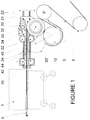
- the device for sequentially feeding a strip 3 into a station 1 working it at a standstill, such as a platen press, this strip arriving upstream continuously mainly comprises a roller drive 10, arranged transversely to the direction of travel of the strip, and above which a satellite roller 20 oscillates, parallel to the drive roller 10, this satellite roller oscillating from upstream to downstream between positions 20 and 20 'substantially in a horizontal plane.
- the moving strip 3, guided by feed rollers 5 and 5 ′ passes below the drive roller 10, performs there between a half and three-quarters of a turn upwards before passing to the above the satellite roller 20, the outlet of which is located at the level of the tools of the platen press 1.
- the upstream displacement of the satellite roller from position 20 ′ to 20 momentarily extends the last loop of the strip, which then stops the portion located in the platen press 1.
- the central axis 12 of the drive roller 10 is held by bearings in the right side walls 7, central 8 and left 9 of the frame, the walls 7 and 8 close together forming a bathtub.
- This drive roller 10 is driven by a reduction motor 18 illustrated diagrammatically on the wall 7 directly in the extension of the axis 12.
- a main toothed wheel 14 is integral with this drive axis 12.
- the central axis of rotation 27 of the satellite roller 20 is, for its part, held by bearings 28 in the upper end of two levers 55, 52/53 both mounted in rotation through bearings on the axis 12 of drive roller.
- the lower branches 53 of these levers are rigidly joined by a low inertia cylinder-cross 56.
- the end of the axle 27 of the satellite roller 20 is integral with a pinion 29 meshed with the main toothed wheel 14. More particularly, this pinion 29 and toothed wheel 14 have an identical diameter, such that the average speeds of rotation of the drive rollers 10 and satellite roller 20 are strictly identical.
- a beautiful 50 hung by means of a bearing on the axis 27 of the satellite roller 20 makes it possible to pull the latter cyclically from upstream to downstream, the parallelism of the roller 20 relative to the roller 10 being maintained by virtue of the cross cylinder 56.
- the device according to the invention further comprises a counterweight 80 in the form of a cylindrical mass mounted in rotation about an axis 74 mounted through a bearing at the upper end of an arm oscillating 70 turning itself, through a bearing 71, around the axis 12 of the drive roller 10.
- the axis 74 is also integral with a counterweight pinion 76 meshed with the main toothed wheel 14. The diameter of the pinion 76 is equal to that of this main gear 14 so that the average speed of rotation of the counterweight 80 is identical to that of the satellite roller 20.
- the axis of rotation of the lever 52/53 consists of a cylinder 51 on the one hand held in the central wall 8 by an external bearing and on the other hand holding, also by means of bearings, the through axis 12 for driving the roller 10.
- This cylinder 51 is completed at its outer end, that is to say between the walls 7 and 8 of the frame constituting a bathtub, by a toothed segment 54 in the form of a circular sector centered on the axis of rotation 12 of the drive roller 10.
- This toothed segment 54 is meshed with a first deflection wheel 61 secured to a deflection axis 60 held at each end by bearings in the walls of the bathtub 7, 8.
- a second return wheel 62 secured to the return axis 60 meshes with an inverting wheel 65 whose axis of rotation, not illustrated, is also held at each end by bearings in the walls 7 and 8 of the bath.
- This reversing wheel 65 is also meshed with a toothed sector 67 of the arm 70, this sector 67 being centered on the bearing 71 of the arm.
- This mechanical transmission therefore prints on the arm 70 an oscillation in rotation in the opposite direction to the levers 55, 52/53.
- the drive roller 10 of the strip 3 as well as the main toothed wheel 14 rotate anticlockwise while the satellite roller 20 driven by its toothed pinion 29 rotates clockwise.
- the cylindrical counterweight 80 driven by its pinion 76 also rotates clockwise.
- the pinion 29 momentarily rolls anti-clockwise along the main toothed wheel 14, which causes, during this movement, a drop in the drive torque consumed by this satellite roller 20.
- the rotary arm 70 driven by the mechanism 54, 60-65, rotates in the direction of clockwise, which causes the pinion 76 to roll along the main gear 14 in the same direction, which momentarily increases the drive torque consumed by this counterweight 80.
- this counterweight 80 is dimensioned so that its moment of inertia with respect to its center of rotation and with respect to the axis 12 of the drive roller 10 is identical to the corresponding moment of inertia of the satellite roller 20, we obtain compensation for momentary variations torque making the load of the motor-reducer 18 on the axis 12, admittedly significant, rigorously constant, which allows the use of particularly efficient electric motors of the "brushless" type.
- the counterweight 80 since it is possible to dimension the mass and inert of the counterweight 80 independently, the counterweight will be dimensioned in mass so as to counterbalance the effect of the mass of the satellite system, and this in a plane horizontal and for the part close to the frame 8.
- a pressure roller 30 acting at the outlet of the roller satellite 20 in order to effectively push the strip forward during a feeding sequence and, in combination, a double telescopic guide shelf consisting of upper and lower quasi-stationary downstream combs 44 between which oscillates a pair of lower movable combs and higher upstream 45.
- two side plates 21 are mounted in rotation about the axis 27 of the satellite roller 20. These plates are engaged by rollers 23 in guide rails 24 movable in rotation 25 at their ends downstream, that is to say close to the platen press 1.
- a horizontal lever 32 On the internal face of each plate is mounted a horizontal lever 32 whose upstream end is held by an axis of rotation while the downstream end is held by a remote-controlled cylinder, the pressing roller being mounted in rotation on these two levers.
- the pressure force of the roller 30 can be adjusted by means of the jacks 34 against the satellite roller 20.
- the side plates 21 guided by the rails 24 make it possible to maintain, by means of two cross tubes 22, the upper and lower oscillating combs downstream 45 in the extension of the stationary combs 44 held on their side by cross tubes 42 fixed to these same rails 24.
- the side plates 21 always remain correctly aligned along the rails 24, and it is the same for the combs constituting a double guide shelf for the strip of paper moving at very high speed during its introduction into the platen press 1.
- the strip 3 remains flat and keeps its register.
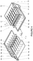
- Figures 4 and 5 illustrate an alternative of the first embodiment in which the combs constituting the double telescopic shelf are confined in two half-boxes: a quasi-stationary 78 downstream connected by a fastener 97 in rotation at a fixed point close to the entrance to the station, or directly to the lower plate if its stroke is short; and an oscillating 79 with the satellite roller 20 which it encompasses and to the axis of which it is connected in rotation, these two half-boxes being connected to each other by longitudinal sliding rails not shown.
- the downstream half-box 78 has a large primary ceiling 84 connected at its downstream end to two small side walls 93 of length between a quarter and a fifth of the length of the ceiling, walls themselves connected to a secondary bottom 83 of length between a third and a quarter of the length of the ceiling.
- the teeth 47 start from the lower edge of a transverse vertical half-wall of upper end, the upper edge of which is connected to the ceiling 84, and end substantially in the middle of the ceiling.
- the vertical plates 87 only start from a certain distance from the transverse half-wall, for example equivalent to one tenth of the length of the ceiling, in order to create an upper transverse chamber 96 'opening on either side and other on upper side windows 94 formed in the side walls.
- a plurality of longitudinal vertical metal plates 89 also emerge from the upper face of the bottom, each carrying a downstream lower comb tooth 49 in the form of a longitudinal horizontal plate, the lower teeth 49 being of the same spacing as the upper teeth, but laterally offset by half a spacing.
- these teeth start from the upper edge of a transverse vertical half-wall of lower end, the lower edge of which is connected to the corresponding edge of the secondary bottom 83; and this end little behind the upper teeth.
- the vertical plates also start only from a certain distance from the transverse half-wall in order to create a lower transverse chamber 96 opening on either side onto lower side windows 95 of side walls 93.
- the upstream half-box 78 has a large primary bottom 82, if desired partially glazed, connected, at the level of the satellite roller 20, to two side walls 90 oblique upstream except for a triangular downstream projection, walls themselves connected to a secondary ceiling 85 having a series of longitudinal grooves in correspondence with the vertical upper plates 87 of the downstream half-box 78.
- the upper faces of the primary bottom 82 and secondary ceiling 85 of the upstream half-box 79 are at height with the faces lower respectively of the secondary bottom 83 and of the primary ceiling 84 of the downstream half-box 78, contact faces where sliding sliding rails can be installed.
- the primary bottom 82 ends upstream, at the level of the satellite roller 20, in an oblique plate held by the side walls 90, oblique plate from which leave triangular ribs 88 for supporting the teeth of the lower upstream comb 48.
- These teeth are here in the form of longitudinal horizontal sheets located laterally between two structures upper tubulars 86.
- each of the tubular structures 86 and at the level of this intermediate horizontal plate 77 is installed one of a series of pressure rollers 31, corresponding to the pressure roller 30 of FIG. 1, permanently maintaining the strip pressed against the satellite roll 20.
- FIG. 5 illustrating, in section, the nesting of the two half-boxes
- the parts of the upstream half-box are hatched in fine lines while the parts of the downstream half-box are hatched in bold line.
- the lower teeth 48 and 49 being found side by side first constitute a lower shelf surmounted by an upper shelf constituted by the upper teeth 46 and 47 also side by side, these tablets being separated by a small height h defining the imposed passage of the strip. This spacing h is also found between the transverse half-walls of upper and lower end of the downstream half-box 78.
- the lower plates 88 and 89 create horizontal longitudinal lower chambers 99 telescopic, while the upper plates 87 associated with tubular structures 86 create horizontal longitudinal upper chambers 98 also telescopic.
- These chambers impose on the ambient air stirred by the oscillating movement of the half-box 79 of the horizontal flows reaching the upstream 91 and downstream 96 transverse chambers where these flows enter and exit laterally always horizontally. Vertical air flows capable of damaging the strip against the upper or lower shelf are thus practically annihilated in this alternative of the first embodiment.
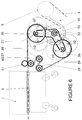
- a device for feeding the strip of the satellite roll to the work station illustrated in FIG. 6 maintaining the correct position of the strip is only ensured by a pair of towing rollers 40, 41 intermittently driven from such that their peripheral speed is practically identical to the intermittent speed of the strip, which makes it possible to permanently apply a slight constant traction on this strip 3 leaving the satellite roll.
- the drive of the satellite roller is used to carry out a secondary differential drive of the tractor roller 40 as illustrated in FIG. 6, and partially on the left-hand side of FIG. 2.
- This drive first comprises a bent vertical lever 33 located on the outer face of the wall 9 on the driver side and mounted free in rotation on an extension of the drive axis 12 of the drive roller 10.
- the end of the substantially vertical upper branch of the lever is crossed by an extension of the drive axis 27 of the satellite roller imparting to this lever its oscillating movement.
- a first upper disc 35 is mounted at the end of this axis 27, ie at the end of this upper branch of the lever 33, and is therefore driven in rotation at the same angular speed as the satellite roller.
- the end of the lower branch oblique downstream of the lever 33 carries a second lower disc 36 whose diameter is identical to the upper disc.
- This drive then comprises a drive hen 37 secured to the end of the axis of the tractor roller 40 and located on the face external of the wall 9 in the same vertical plane containing the discs 35 and 36 thus allowing the installation of an endless belt 59 passing around these discs and pulley.
- a rear pulley 38 and a return pulley 39 from the belt to the lower disc 36 are also provided.
- the angle of the lever 33 and the arrangement of the chicken 39 are such that the path of the belt 59 has a symmetry with respect to the line (x) connecting the axis of rotation 12 of the lever and the axis of rotation of the rear pulley 38 when the upper branch of the lever 33 is vertical, that is to say in the central oscillation position.
- the satellite roller and the upper disc 35 are pulled back towards the position a1
- the increase in the upper horizontal path of travel of the belt 59 is compensated by a decrease of equal value in the travel path between the pulley of reference 39 and the lower disc 36 having advanced into its position a1.
- An opposite effect appears when the disc 35 advances towards the position a2 causing the lower disc 36 to recede. Thanks to this arrangement, the length of the path remains virtually constant, the minimal variations being absorbed without further by the elasticity of the belt.
- the diameter of the disc 35 is equal to that of the satellite roller 20 to which it is directly connected, and that the diameter of the hen 37 is equal to that of the tractor roller 40 to which it is also directly connected, we notes then that the speed and the intermittent acceleration of movement of the belt 59 between the disc 35 and the pulley 37 is strictly identical to that of the strip 3, and the same is true for the peripheral speed of the tractor roller 40.
- This roller 40 therefore effectively pulls the strip at the right time, and this under a constant pre-established tension.
- the diameter of the disc 35 can be different from that of the roller 20 provided that the same is true between the pulley 37 and the roller 40.
- the counterweight 80 will then be resized to also balance the additional inertias of the rollers 40, 41, etc. (see figure 6).
- this second embodiment of feeding the strip into work station 1 appears lighter and therefore less inert than the first using pressure rollers and a telescopic table, it is obviously possible to combine them to perfect the control of this strip.
- the tube 10 can be replaced by the extension of the axis 60 towards the frame 9 and the addition of a pinion / toothed segment arrangement similar to the figures 61/54 on the lever 55, the tube 10 and the extended axis 60 each having specific advantages in practice.
Landscapes
- Advancing Webs (AREA)
- Replacement Of Web Rolls (AREA)
- Controlling Rewinding, Feeding, Winding, Or Abnormalities Of Webs (AREA)
- Folding Of Thin Sheet-Like Materials, Special Discharging Devices, And Others (AREA)
- Electric Propulsion And Braking For Vehicles (AREA)
- Registering, Tensioning, Guiding Webs, And Rollers Therefor (AREA)
- Sewing Machines And Sewing (AREA)
- Manufacturing Of Electric Cables (AREA)
Applications Claiming Priority (2)
| Application Number | Priority Date | Filing Date | Title |
|---|---|---|---|
| CH1305/95 | 1995-05-08 | ||
| CH01305/95A CH690547A5 (fr) | 1995-05-08 | 1995-05-08 | Dispositif d'alimentation d'une bande dans une station la travaillant à l'arrêt, cette bande arrivant de manière continue. |
Publications (3)
| Publication Number | Publication Date |
|---|---|
| EP0742170A2 true EP0742170A2 (de) | 1996-11-13 |
| EP0742170A3 EP0742170A3 (de) | 1997-10-22 |
| EP0742170B1 EP0742170B1 (de) | 1999-02-10 |
Family
ID=4207340
Family Applications (1)
| Application Number | Title | Priority Date | Filing Date |
|---|---|---|---|
| EP96106944A Expired - Lifetime EP0742170B1 (de) | 1995-05-08 | 1996-05-03 | Vorrichtung zum Zuführen einer kontinuierlich ankommenden Bahn in einer Station, die sie in angehaltenem Zustand bearbeitet |
Country Status (12)
| Country | Link |
|---|---|
| US (1) | US5685472A (de) |
| EP (1) | EP0742170B1 (de) |
| JP (1) | JP2634041B2 (de) |
| KR (1) | KR100199354B1 (de) |
| CN (1) | CN1071279C (de) |
| AT (1) | ATE176655T1 (de) |
| BR (1) | BR9602194A (de) |
| CA (1) | CA2175981C (de) |
| CH (1) | CH690547A5 (de) |
| DE (1) | DE69601511T2 (de) |
| DK (1) | DK0742170T3 (de) |
| ES (1) | ES2128806T3 (de) |
Cited By (4)
| Publication number | Priority date | Publication date | Assignee | Title |
|---|---|---|---|---|
| WO2010063353A1 (fr) * | 2008-12-04 | 2010-06-10 | Bobst Sa | Dispositif d'alimentation d'une unité de transformation avec un support en bande continue pour une station d'alimentation dans une machine de production d'emballages |
| WO2012007092A1 (fr) | 2010-07-14 | 2012-01-19 | Bobst Sa | Procede de protection d'une unite de transformation d'un support en bande, station d'alimentation et machine de production d'emballages |
| WO2020052809A1 (fr) * | 2018-09-10 | 2020-03-19 | Bobst Mex Sa | Dispositif de deroulage de bande et machine d'estampage d'elements en forme de feuilles |
| US11577482B2 (en) | 2013-05-29 | 2023-02-14 | Bobst Mx Sa | Unit for converting a continuous web substrate, and packaging production machine thus equipped |
Families Citing this family (6)
| Publication number | Priority date | Publication date | Assignee | Title |
|---|---|---|---|---|
| US6997712B2 (en) * | 2003-10-06 | 2006-02-14 | Yong Woon Kim | Tooth containing image thereon |
| CN102280208A (zh) * | 2011-07-08 | 2011-12-14 | 江苏亨通高压电缆有限公司 | 一种多面皮带牵引装置 |
| CN107934628A (zh) * | 2017-12-14 | 2018-04-20 | 杭州春来科技有限公司 | 滤纸阻滞扭矩保持装置 |
| CN108906919B (zh) * | 2018-07-17 | 2024-03-22 | 宣化钢铁集团有限责任公司 | 一种带有滑板导向垂直压下的连续矫直机 |
| CN113878629B (zh) * | 2021-09-24 | 2023-03-10 | 温州市众邦拉链有限公司 | 一种拉链带裁切设备 |
| CN118003270B (zh) * | 2024-04-10 | 2024-06-04 | 珠海博杰电子股份有限公司 | 一种固带机构 |
Family Cites Families (8)
| Publication number | Priority date | Publication date | Assignee | Title |
|---|---|---|---|---|
| US3058683A (en) * | 1959-02-09 | 1962-10-16 | Atvidabergs Ind Ab | Tape handling device |
| US3667354A (en) * | 1969-01-30 | 1972-06-06 | Rotographic Machinery Co | Web fed rotary variable repeat cutter-creaser system |
| DE2149483A1 (de) * | 1971-10-04 | 1973-04-19 | Hans Stang | Einlaufvorrichtung fuer mehrere, nebeneinander angeordnete textile baender |
| FR2214295A5 (de) * | 1973-01-11 | 1974-08-09 | Etudes De Machines Speciales | |
| CH602462A5 (de) * | 1975-11-26 | 1978-07-31 | Bobst Fils Sa J | |
| FR2618770B1 (fr) * | 1987-07-30 | 1990-01-05 | Chambon Machines | Dispositif d'alimentation pour une machine travaillant sur une nappe de materiau a l'arret, notamment pour une presse a decouper a plat |
| CH679134A5 (de) * | 1989-05-03 | 1991-12-31 | Bruderer Ag | |
| US5197645A (en) * | 1989-09-07 | 1993-03-30 | Nordlof Richard D | Roll type stock feed apparatus with pneumatically actuated roll release |
-
1995
- 1995-05-08 CH CH01305/95A patent/CH690547A5/fr not_active IP Right Cessation
-
1996
- 1996-05-03 DE DE69601511T patent/DE69601511T2/de not_active Expired - Lifetime
- 1996-05-03 EP EP96106944A patent/EP0742170B1/de not_active Expired - Lifetime
- 1996-05-03 ES ES96106944T patent/ES2128806T3/es not_active Expired - Lifetime
- 1996-05-03 DK DK96106944T patent/DK0742170T3/da active
- 1996-05-03 AT AT96106944T patent/ATE176655T1/de not_active IP Right Cessation
- 1996-05-07 CA CA002175981A patent/CA2175981C/en not_active Expired - Fee Related
- 1996-05-07 JP JP8112358A patent/JP2634041B2/ja not_active Expired - Fee Related
- 1996-05-07 KR KR1019960014904A patent/KR100199354B1/ko not_active Expired - Fee Related
- 1996-05-08 CN CN96105121A patent/CN1071279C/zh not_active Expired - Fee Related
- 1996-05-08 BR BR9602194A patent/BR9602194A/pt not_active IP Right Cessation
- 1996-05-08 US US08/647,022 patent/US5685472A/en not_active Expired - Lifetime
Cited By (9)
| Publication number | Priority date | Publication date | Assignee | Title |
|---|---|---|---|---|
| WO2010063353A1 (fr) * | 2008-12-04 | 2010-06-10 | Bobst Sa | Dispositif d'alimentation d'une unité de transformation avec un support en bande continue pour une station d'alimentation dans une machine de production d'emballages |
| US8733222B2 (en) | 2008-12-04 | 2014-05-27 | Bobst Mex Sa | Device for feeding a converting unit with a web substrate for a feeding station in a packaging production machine |
| WO2012007092A1 (fr) | 2010-07-14 | 2012-01-19 | Bobst Sa | Procede de protection d'une unite de transformation d'un support en bande, station d'alimentation et machine de production d'emballages |
| US10829331B2 (en) | 2010-07-14 | 2020-11-10 | Bobst Mex Sa | Method for protecting a converting unit for converting a web substrate, feeding station and packaging production machine |
| US11577482B2 (en) | 2013-05-29 | 2023-02-14 | Bobst Mx Sa | Unit for converting a continuous web substrate, and packaging production machine thus equipped |
| WO2020052809A1 (fr) * | 2018-09-10 | 2020-03-19 | Bobst Mex Sa | Dispositif de deroulage de bande et machine d'estampage d'elements en forme de feuilles |
| KR20210032533A (ko) * | 2018-09-10 | 2021-03-24 | 봅스트 맥스 에스에이 | 스트립을 언롤링하기 위한 디바이스 및 시트 형태로 요소들을 스탬핑하기 위한 기계 |
| RU2758611C1 (ru) * | 2018-09-10 | 2021-11-01 | Бобст Мекс Са | Устройство разматывания ленты и машина тиснения элементов в виде листов |
| US11180335B2 (en) | 2018-09-10 | 2021-11-23 | Bobst Mex Sa | Device for unwinding strips and machine for stamping elements in sheet form |
Also Published As
| Publication number | Publication date |
|---|---|
| BR9602194A (pt) | 1998-04-07 |
| KR960041021A (ko) | 1996-12-17 |
| ES2128806T3 (es) | 1999-05-16 |
| CA2175981A1 (en) | 1996-11-09 |
| DE69601511D1 (de) | 1999-03-25 |
| CA2175981C (en) | 2000-05-16 |
| CN1136005A (zh) | 1996-11-20 |
| EP0742170A3 (de) | 1997-10-22 |
| CN1071279C (zh) | 2001-09-19 |
| DE69601511T2 (de) | 1999-07-08 |
| KR100199354B1 (ko) | 1999-06-15 |
| CH690547A5 (fr) | 2000-10-13 |
| JP2634041B2 (ja) | 1997-07-23 |
| JPH08310700A (ja) | 1996-11-26 |
| EP0742170B1 (de) | 1999-02-10 |
| US5685472A (en) | 1997-11-11 |
| ATE176655T1 (de) | 1999-02-15 |
| DK0742170T3 (da) | 1999-09-20 |
Similar Documents
| Publication | Publication Date | Title |
|---|---|---|
| EP1617987B1 (de) | Vorrichtung zum simultanstrecken von folien in längsrichtung und in querrichtung | |
| FR2565897A1 (fr) | Dispositif tendeur de nappe pour machine a fabriquer des sacs en matiere thermoplastique | |
| EP0742170B1 (de) | Vorrichtung zum Zuführen einer kontinuierlich ankommenden Bahn in einer Station, die sie in angehaltenem Zustand bearbeitet | |
| FR2619094A1 (fr) | Dispositif d'empilage d'objets plats disposes en paquets | |
| FR2544704A1 (fr) | Appareil et procede pour plier transversalement des bandes de papier | |
| EP3426584A1 (de) | Kettenspanner, maschine zur verarbeitung von blattförmigen elementen und verfahren zum spannen der kettensätze | |
| FR2621025A1 (fr) | Appareil pour le pliage de materiaux en feuilles | |
| EP0305230B1 (de) | Periodische Papierbahnzufuhr einer Maschine, insbesondere für eine blattabschneidende Presse | |
| EP2704973B1 (de) | Vorrichtung zum stapeln von papierbögen oder dergleichen | |
| EP0638496A1 (de) | Vorrichtung und Verfahren zum Einführen von blattformigem Material in eine Maschine | |
| FR2491385A1 (fr) | Massicot et procede de decoupe de flans de carton | |
| FR2624830A1 (fr) | Empileur d'etiquettes et procede d'empilage associe | |
| CH365259A (fr) | Mécanisme provoquant le transport pas à pas d'un tronçon de ruban sur un secteur déterminé, indépendamment des mouvements effectués par le reste du ruban | |
| EP1393903B1 (de) | Rotationspresse zum Anbringen von einem Bild auf ein Substrat | |
| FR2555507A1 (fr) | Presse rotative pour l'impression de formulaires de commerce | |
| FR2684601A1 (fr) | Dispositif de pliage pour machines rotatives a imprimer. | |
| FR2613706A1 (fr) | Dispositif pour introduire des feuilles dans une machine les travaillant | |
| EP0267431B1 (de) | Einrichtung zum Stapeln von flachen Gegenständen | |
| CH682995A5 (fr) | Dispositif d'interception de feuilles déposées sur le haut d'une pile dans une machine de production d'emballages. | |
| EP1588968B1 (de) | Trag- und Antriebsmodul eines aufgespulten bahnförmigen Materials für eine Bearbeitungsmaschine | |
| EP2484511A1 (de) | Ultraschall-Schweißvorrichtung | |
| CH359593A (fr) | Dispositif permettant d'intercepter en cours de distribution des feuilles déposées une à une en pile | |
| BE1011594A3 (fr) | Procede de decoupage d'affiches et dispositif pour sa mise en oeuvre. | |
| CH406775A (fr) | Mécanisme provoquant le transport pas á pas de ruban sur un secteur déterminé, indépendamment des mouvements effectués par le reste du ruban | |
| BE542388A (de) |
Legal Events
| Date | Code | Title | Description |
|---|---|---|---|
| PUAI | Public reference made under article 153(3) epc to a published international application that has entered the european phase |
Free format text: ORIGINAL CODE: 0009012 |
|
| 17P | Request for examination filed |
Effective date: 19960506 |
|
| AK | Designated contracting states |
Kind code of ref document: A2 Designated state(s): AT BE DE DK ES FR GB IT LU NL SE |
|
| PUAL | Search report despatched |
Free format text: ORIGINAL CODE: 0009013 |
|
| RHK1 | Main classification (correction) |
Ipc: B65H 20/04 |
|
| AK | Designated contracting states |
Kind code of ref document: A3 Designated state(s): AT BE DE DK ES FR GB IT LU NL SE |
|
| GRAG | Despatch of communication of intention to grant |
Free format text: ORIGINAL CODE: EPIDOS AGRA |
|
| GRAH | Despatch of communication of intention to grant a patent |
Free format text: ORIGINAL CODE: EPIDOS IGRA |
|
| 17Q | First examination report despatched |
Effective date: 19980331 |
|
| GRAH | Despatch of communication of intention to grant a patent |
Free format text: ORIGINAL CODE: EPIDOS IGRA |
|
| GRAA | (expected) grant |
Free format text: ORIGINAL CODE: 0009210 |
|
| AK | Designated contracting states |
Kind code of ref document: B1 Designated state(s): AT BE DE DK ES FR GB IT LU NL SE |
|
| REF | Corresponds to: |
Ref document number: 176655 Country of ref document: AT Date of ref document: 19990215 Kind code of ref document: T |
|
| REF | Corresponds to: |
Ref document number: 69601511 Country of ref document: DE Date of ref document: 19990325 |
|
| GBT | Gb: translation of ep patent filed (gb section 77(6)(a)/1977) |
Effective date: 19990304 |
|
| ITF | It: translation for a ep patent filed | ||
| REG | Reference to a national code |
Ref country code: ES Ref legal event code: FG2A Ref document number: 2128806 Country of ref document: ES Kind code of ref document: T3 |
|
| REG | Reference to a national code |
Ref country code: DK Ref legal event code: T3 |
|
| PLBE | No opposition filed within time limit |
Free format text: ORIGINAL CODE: 0009261 |
|
| STAA | Information on the status of an ep patent application or granted ep patent |
Free format text: STATUS: NO OPPOSITION FILED WITHIN TIME LIMIT |
|
| 26N | No opposition filed | ||
| REG | Reference to a national code |
Ref country code: GB Ref legal event code: IF02 |
|
| PGFP | Annual fee paid to national office [announced via postgrant information from national office to epo] |
Ref country code: AT Payment date: 20070412 Year of fee payment: 12 |
|
| PGFP | Annual fee paid to national office [announced via postgrant information from national office to epo] |
Ref country code: SE Payment date: 20070511 Year of fee payment: 12 Ref country code: LU Payment date: 20070511 Year of fee payment: 12 |
|
| PGFP | Annual fee paid to national office [announced via postgrant information from national office to epo] |
Ref country code: DK Payment date: 20070523 Year of fee payment: 12 |
|
| PGFP | Annual fee paid to national office [announced via postgrant information from national office to epo] |
Ref country code: GB Payment date: 20070423 Year of fee payment: 12 |
|
| PGFP | Annual fee paid to national office [announced via postgrant information from national office to epo] |
Ref country code: BE Payment date: 20070424 Year of fee payment: 12 |
|
| BERE | Be: lapsed |
Owner name: S.A. *BOBST Effective date: 20080531 |
|
| REG | Reference to a national code |
Ref country code: DK Ref legal event code: EBP |
|
| GBPC | Gb: european patent ceased through non-payment of renewal fee |
Effective date: 20080503 |
|
| PG25 | Lapsed in a contracting state [announced via postgrant information from national office to epo] |
Ref country code: AT Free format text: LAPSE BECAUSE OF NON-PAYMENT OF DUE FEES Effective date: 20080503 |
|
| PG25 | Lapsed in a contracting state [announced via postgrant information from national office to epo] |
Ref country code: BE Free format text: LAPSE BECAUSE OF NON-PAYMENT OF DUE FEES Effective date: 20080531 |
|
| PG25 | Lapsed in a contracting state [announced via postgrant information from national office to epo] |
Ref country code: DK Free format text: LAPSE BECAUSE OF NON-PAYMENT OF DUE FEES Effective date: 20080531 |
|
| PG25 | Lapsed in a contracting state [announced via postgrant information from national office to epo] |
Ref country code: GB Free format text: LAPSE BECAUSE OF NON-PAYMENT OF DUE FEES Effective date: 20080503 |
|
| PG25 | Lapsed in a contracting state [announced via postgrant information from national office to epo] |
Ref country code: LU Free format text: LAPSE BECAUSE OF NON-PAYMENT OF DUE FEES Effective date: 20080503 |
|
| PG25 | Lapsed in a contracting state [announced via postgrant information from national office to epo] |
Ref country code: SE Free format text: LAPSE BECAUSE OF NON-PAYMENT OF DUE FEES Effective date: 20080504 |
|
| PGFP | Annual fee paid to national office [announced via postgrant information from national office to epo] |
Ref country code: ES Payment date: 20120607 Year of fee payment: 17 |
|
| PGFP | Annual fee paid to national office [announced via postgrant information from national office to epo] |
Ref country code: DE Payment date: 20130515 Year of fee payment: 18 |
|
| PGFP | Annual fee paid to national office [announced via postgrant information from national office to epo] |
Ref country code: NL Payment date: 20130510 Year of fee payment: 18 Ref country code: IT Payment date: 20130515 Year of fee payment: 18 Ref country code: FR Payment date: 20130612 Year of fee payment: 18 |
|
| REG | Reference to a national code |
Ref country code: DE Ref legal event code: R119 Ref document number: 69601511 Country of ref document: DE |
|
| REG | Reference to a national code |
Ref country code: NL Ref legal event code: V1 Effective date: 20141201 |
|
| PG25 | Lapsed in a contracting state [announced via postgrant information from national office to epo] |
Ref country code: NL Free format text: LAPSE BECAUSE OF NON-PAYMENT OF DUE FEES Effective date: 20141201 |
|
| REG | Reference to a national code |
Ref country code: FR Ref legal event code: ST Effective date: 20150130 |
|
| REG | Reference to a national code |
Ref country code: DE Ref legal event code: R119 Ref document number: 69601511 Country of ref document: DE Effective date: 20141202 |
|
| PG25 | Lapsed in a contracting state [announced via postgrant information from national office to epo] |
Ref country code: DE Free format text: LAPSE BECAUSE OF NON-PAYMENT OF DUE FEES Effective date: 20141202 Ref country code: IT Free format text: LAPSE BECAUSE OF NON-PAYMENT OF DUE FEES Effective date: 20140503 |
|
| PG25 | Lapsed in a contracting state [announced via postgrant information from national office to epo] |
Ref country code: FR Free format text: LAPSE BECAUSE OF NON-PAYMENT OF DUE FEES Effective date: 20140602 |
|
| REG | Reference to a national code |
Ref country code: ES Ref legal event code: FD2A Effective date: 20150629 |
|
| PG25 | Lapsed in a contracting state [announced via postgrant information from national office to epo] |
Ref country code: ES Free format text: LAPSE BECAUSE OF NON-PAYMENT OF DUE FEES Effective date: 20140504 |