EP0742171A2 - Fotoelektrischer Sensor für eine Vorrichtung zur Registerregelung in einer Rotationsdruckmaschine - Google Patents
Fotoelektrischer Sensor für eine Vorrichtung zur Registerregelung in einer Rotationsdruckmaschine Download PDFInfo
- Publication number
- EP0742171A2 EP0742171A2 EP96107030A EP96107030A EP0742171A2 EP 0742171 A2 EP0742171 A2 EP 0742171A2 EP 96107030 A EP96107030 A EP 96107030A EP 96107030 A EP96107030 A EP 96107030A EP 0742171 A2 EP0742171 A2 EP 0742171A2
- Authority
- EP
- European Patent Office
- Prior art keywords
- reading
- spherical
- optical
- row
- strip
- Prior art date
- Legal status (The legal status is an assumption and is not a legal conclusion. Google has not performed a legal analysis and makes no representation as to the accuracy of the status listed.)
- Granted
Links
Images
Classifications
-
- G—PHYSICS
- G01—MEASURING; TESTING
- G01B—MEASURING LENGTH, THICKNESS OR SIMILAR LINEAR DIMENSIONS; MEASURING ANGLES; MEASURING AREAS; MEASURING IRREGULARITIES OF SURFACES OR CONTOURS
- G01B11/00—Measuring arrangements characterised by the use of optical techniques
-
- B—PERFORMING OPERATIONS; TRANSPORTING
- B65—CONVEYING; PACKING; STORING; HANDLING THIN OR FILAMENTARY MATERIAL
- B65H—HANDLING THIN OR FILAMENTARY MATERIAL, e.g. SHEETS, WEBS, CABLES
- B65H43/00—Use of control, checking, or safety devices, e.g. automatic devices comprising an element for sensing a variable
- B65H43/08—Photoelectric devices
-
- B—PERFORMING OPERATIONS; TRANSPORTING
- B41—PRINTING; LINING MACHINES; TYPEWRITERS; STAMPS
- B41F—PRINTING MACHINES OR PRESSES
- B41F33/00—Indicating, counting, warning, control or safety devices
-
- B—PERFORMING OPERATIONS; TRANSPORTING
- B65—CONVEYING; PACKING; STORING; HANDLING THIN OR FILAMENTARY MATERIAL
- B65H—HANDLING THIN OR FILAMENTARY MATERIAL, e.g. SHEETS, WEBS, CABLES
- B65H23/00—Registering, tensioning, smoothing or guiding webs
- B65H23/04—Registering, tensioning, smoothing or guiding webs longitudinally
- B65H23/046—Sensing longitudinal register of web
-
- B—PERFORMING OPERATIONS; TRANSPORTING
- B65—CONVEYING; PACKING; STORING; HANDLING THIN OR FILAMENTARY MATERIAL
- B65H—HANDLING THIN OR FILAMENTARY MATERIAL, e.g. SHEETS, WEBS, CABLES
- B65H2511/00—Dimensions; Position; Numbers; Identification; Occurrences
- B65H2511/50—Occurence
- B65H2511/51—Presence
- B65H2511/512—Marks, e.g. invisible to the human eye; Patterns
Definitions
- the present invention relates to a photoelectric detector for a device for controlling the register of a plurality of successive prints on a moving strip in a rotary printing machine.
- Such a device makes it possible to automatically correct the position of the strip and / or the printing cylinders of each color station as a function of register errors calculated from the detection of the relative positions of mark marks printed in a reserved area, and this successively by each station.
- a control device appreciated for its ratio between its performance and its reasonable production cost is based on two photoelectric detectors each formed by a row of photodiodes. Such a device is described in Swiss patent application CH 03318 / 91-5, description forming part of this presentation. These two parallel detectors are arranged transversely with respect to the direction of travel of the strip over an area through which the reference marks pass, for example in the margin.
- a first advantage of this device is that it can work with reference micro-marks, that is to say marks of the order of 1 mm 2, owing to the fact that a row consists of around twenty photodiodes with a surface reduced to about 0.7 mm2 arranged every millimeter.
- Another advantage of this device is that it can work as well with marks printed side by side as with marks printed one behind the other, even in a simplified version comprising only two rows of photodiodes.
- the rows are divided into two lateral halves, the first row measuring the position of passage of the marks for the determination of the lateral error, the second row measuring the time offset of the passage of the marks for the determination of the longitudinal error.
- a row measures the position of passage of a mark, then, after reinitialization, the position of passage of the next mark for determining the lateral error, and the two rows, spaced by a distance corresponding to the expected longitudinal difference between two marks, measure a time difference in the normally simultaneous passage of the marks.
- each mark reading device consists of a pair of optical fiber bundles of 0.2 mm in diameter: a bundle of optical fibers d lighting and a bundle of optical fibers for receiving the reflected light which is brought to a photodiode situated far back in the machine.
- the cone of entry or exit of light in an optical fiber being of the order of 60 °
- the light spot and the reading area correspond to a usual diameter circle of 4 mm.
- Amply sufficient for standard marks, for example rectangular of 1 mm by 5 mm these reading devices become inadequate for micro-marks reduced to 1 mm by 1 mm. In fact, the expected maximum variation in light intensity is then reduced to a quarter, and becomes even less in the case of pale-colored micro-marks.
- the object of the present invention is a photoelectric detector for a register control device comprising a row of mark reading devices arranged opposite the strip transversely to the direction of travel.
- This detector must first of all be small enough to be able to be installed in any place of the machine, while being precise enough to locate reliably marks of small dimensions, of the order of a millimeter. Obviously, this detector must also be rigid enough to withstand the stresses of heat and vibration of the machine, and be easily achievable to reduce the manufacturing costs accordingly.
- each reading device comprises a single optical reading fiber associated with its own image focusing device by an adhesive of optical quality, each fiber conducting the light received towards a corresponding photodiode situated behind in the machine.
- each image focusing device is a spherical lens wedged against a seat arranged in a corresponding box belonging to a row of boxes produced within a housing arranged opposite the strip , box at the bottom of which is flush with the end of the corresponding single optical fiber for reading, the space of the box located between the spherical lens and the fiber being occupied by a block of glue of optical quality.
- optical quality adhesive means an adhesive which, once hardened, becomes transparent with a rigorously homogeneous index of refraction throughout its mass.
- the glue block constitutes with the spherical lens, commonly available on the market, a rigid objective making it possible to very precisely define the field of vision.
- the refractive index of the glue block is substantially equal to that of the spherical lens.
- the light rays are then not deflected between the spherical lens and the glue block, which considerably simplifies the calculation of the focal distances in order to take advantage of the entire front surface of the spherical lens to transmit a maximum of reflected light.
- the space of the box located between the spherical lens and a front window for protecting the row of boxes is also occupied by the block of glue of optical quality, the refractive index of the spherical lens being greater than that of glue.
- this embodiment is easier, in particular by the use of an adhesive which, in the liquid state, is sufficiently fluid to bypass the lens by capillarity.
- each image focusing device is a substantially semi-spherical lens of a row arranged or attached against the external face of a front window closing a row in correspondence of boxes produced within a housing disposed opposite the strip, the corresponding box, at the bottom of which is flush with the end of the corresponding single optical fiber, being occupied by a block of optical glue.
- the distance between the spherical or semi-spherical lenses and the strip as well as the distance between the spherical lenses and their single reading optical fibers are established so that the reading area is a circle with a radius between 0.8 and 1.5 mm and the sharpness of this reading zone gradually fades on the periphery.
- the boxes, of internal width equal to common diameter of the spherical lenses have an external width such that, once joined to form a row behind a protective glass of a housing, the reading zones overlap over a predetermined width. Thus, a mark passing between two zones is still detected reliably.
- only one or two optical lighting fibers are associated with each reading device, and, preferably, are arranged near the corresponding image focusing device.
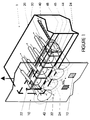
- FIG. 1 is illustrated a photoelectric reading head 1 disposed opposite a moving strip 10 in order to read the position of registration marks 12 successively printed by the preceding color stations, and this side by side or the one behind the other.
- This read head 1 is in the form of a rectangular box 20 in the front face of which is opened a window 22 provided with a protective glass 24. Behind this glass 24 is installed a lateral row of mark reading devices each comprising a pair of optical fibers: respectively upper lighting optical fibers 30 and reading optical fibers 40 also called receiving optical fibers.
- the dimensions of the housing 1 are of the order of 3 to 5 mm high and 20 mm or 40 mm wide respectively for a row of 16 or 32 reading devices.
- the light injected into the optical lighting fibers 30 by a light source located behind in the machine emerges from these fibers at the level of the read head 1 in a cone of angle at the top of the order of 60 ° to create each a light spot 32 with a diameter between 2 and 3 mm, the light spots of this upper row of lighting optical fibers 30 overlapping to practically form a light bar transverse to the strip.
- each optical reading fiber 40 is flush with the central part of the bottom wall of a box 26, this bottom wall having a conical shape oriented towards the fiber.
- Each box 26 has a step substantially in the middle of its upper and lower faces, these steps forming a seat 45 for precise positioning for a spherical lens 44.
- This lens 44 is held in position by a block of glue 48 occupying the entire interior space of the box 26 located between the spherical lens 44 and the optical fiber 40.
- the boxes 26 are glued side by side to form a rigid row of photoelectric reading elements arranged at strictly regular intervals.
- the adhesive forming the block 48 is in particular of optical quality, that is to say that once hardened it becomes absolutely transparent with a homogeneous and isotropic refractive index throughout its volume.
- Such an adhesive is, for example, marketed under the name "Epotek” by the Swiss company Abatec under the reference 1103.
- the first function of this block of adhesive 48 adhering against the rear walls of the box 26 is to hold securely on the one hand the spherical lens 44 in its seat 45 and on the other hand the end of the optical reading fiber 40 at the bottom of the box 26, therefore to maintain this fiber end at a strict and predetermined distance from the spherical lens 44.
- the second function of this block of glue 48 is to constitute, with the spherical lens 44, an objective for the reception of the reflected light coming strictly from a reading area 42 of strictly predetermined size.
- the refractive index of the block 48 is then practically equal to the refractive index of the spherical lens 44, of the order of 1.5, so that a light ray is not deflected at 1 'sphere / block interface.
- the spacing of the optical reading fiber 40 and the spherical lens 44, as well as the spacing of the reading head 1 and of the strip 10 are then established as a function of the lateral spacing of the spherical lenses 44 within their row so that the reading zones 42 are formed by a lateral row of circles with a diameter between 0.8 and 1.5 mm overlapping laterally over a distance e between 0.1 mm and 0.3 mm , and this with a minimal error tolerance.
- the distances mentioned above are established so that the sharpness of the reading areas 42 gradually fades on the periphery, so that the overlapping areas are read half by one fiber and half by the other. adjacent fiber.
- the fibers are bonded to a part provided with bores having a good spacing, then a second part is attached to this part, the bores of which serve to guide the spherical lenses and finally, optical glue is injected into a groove arranged in the second part so as to seal the whole.
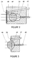
- the whole of the box 26 is filled with glue, thus embedding the spherical lens 44 ′ between a rear block 48 in contact, as before, with the bottom of the box and the reading optical fiber. 40, and a front block 48 ′ in contact with the protective glass 24.
- the refractive index of the spherical lens 44 ′ is greater than that of the adhesive, for example 1.30. This variant is then even more rigid than the previous example insofar as the protective glass is also held securely relative to the lens.
- a row of substantially semi-spherical lenses 46 is arranged on the external face of the protective glass 25.
- semi-spherical is meant a lens of which only one of the faces is a portion of a sphere , the other face being strictly planar.
- These lenses can be molded with ice, or cut from thicker ice, or simply simply glued individually to the outside of the ice.
- the length of the box 27 is then reduced to the value of the distance between the end of the optical fiber 40 flush with the bottom and the lens 46, this box being filled, as before, with a block of retaining glue 49.
- these reading devices being composed of passive elements, namely optical fibers associated with spherical or semi-spherical lenses by means of glue blocks, they can be installed in very rigidly stored in a case 20 also solid but very small, that is to say capable of being installed anywhere in the rotary printing machine.
- the plurality of boxes can be molded in one piece with the housing, and in very precise dimensions especially for the seats of spherical lenses. Despite the rigorous dimensions to be observed, these photoelectric detectors are therefore also easy to produce.
Landscapes
- General Physics & Mathematics (AREA)
- Physics & Mathematics (AREA)
- Inking, Control Or Cleaning Of Printing Machines (AREA)
- Controlling Sheets Or Webs (AREA)
- Optical Couplings Of Light Guides (AREA)
- Handling Of Sheets (AREA)
- Photometry And Measurement Of Optical Pulse Characteristics (AREA)
- Length Measuring Devices By Optical Means (AREA)
- Investigating Materials By The Use Of Optical Means Adapted For Particular Applications (AREA)
- Advancing Webs (AREA)
- Replacement Of Web Rolls (AREA)
- Geophysics And Detection Of Objects (AREA)
- Facsimile Scanning Arrangements (AREA)
- Optical Transform (AREA)
Applications Claiming Priority (3)
| Application Number | Priority Date | Filing Date | Title |
|---|---|---|---|
| CH1304/95 | 1995-05-08 | ||
| CH01304/95A CH690544A5 (fr) | 1995-05-08 | 1995-05-08 | Détecteur photoélectrique pour un dispositif de contrôle du registre dans une machine d'impression rotative. |
| CH130495 | 1995-05-08 |
Publications (3)
| Publication Number | Publication Date |
|---|---|
| EP0742171A2 true EP0742171A2 (de) | 1996-11-13 |
| EP0742171A3 EP0742171A3 (de) | 1997-11-12 |
| EP0742171B1 EP0742171B1 (de) | 2001-07-18 |
Family
ID=4207313
Family Applications (1)
| Application Number | Title | Priority Date | Filing Date |
|---|---|---|---|
| EP96107030A Expired - Lifetime EP0742171B1 (de) | 1995-05-08 | 1996-05-04 | Fotoelektrischer Sensor für eine Vorrichtung zur Registerregelung in einer Rotationsdruckmaschine |
Country Status (14)
| Country | Link |
|---|---|
| US (1) | US5747795A (de) |
| EP (1) | EP0742171B1 (de) |
| JP (1) | JP3252087B2 (de) |
| KR (1) | KR100225163B1 (de) |
| CN (1) | CN1060743C (de) |
| AT (1) | ATE203224T1 (de) |
| AU (1) | AU699040B2 (de) |
| BR (1) | BR9602192A (de) |
| CA (1) | CA2175979C (de) |
| CH (1) | CH690544A5 (de) |
| DE (1) | DE69613892T2 (de) |
| DK (1) | DK0742171T3 (de) |
| ES (1) | ES2160741T3 (de) |
| TW (1) | TW309689B (de) |
Cited By (3)
| Publication number | Priority date | Publication date | Assignee | Title |
|---|---|---|---|---|
| US6586739B2 (en) * | 1999-12-11 | 2003-07-01 | Metso Automation Oy | Device for detecting characteristics of a moving paper web |
| WO2007077073A1 (de) * | 2006-01-05 | 2007-07-12 | Koenig & Bauer Aktiengesellschaft | System zur aufnahme eines bildes von zumindest einem teil einer oberfläche eines flächigen materials |
| ES2401254R1 (es) * | 2011-04-18 | 2013-06-18 | Tna Australia Pty Ltd | Escaner de codigos de barras |
Families Citing this family (7)
| Publication number | Priority date | Publication date | Assignee | Title |
|---|---|---|---|---|
| AU2940497A (en) * | 1996-05-14 | 1997-12-05 | Michel Sayag | Method and apparatus for generating a control signal |
| WO2001042765A2 (de) * | 1999-12-11 | 2001-06-14 | Qualico Gmbh | Vorrichtung zum erfassen von eigenschaften einer bewegten papierbahn mit einer ir-lichtquelle |
| CH694184A5 (fr) * | 2000-12-27 | 2004-08-31 | Bobst Sa | Dispositif de lecture de marques de rep'rage dans une machine d'impression polychrome. |
| US20110267637A1 (en) * | 2009-01-16 | 2011-11-03 | Ecoaxis Systems Pvt. Ltd. | Automatic register control system with intelligent optical sensor and dry presetting facility |
| CN102896892B (zh) * | 2012-10-25 | 2015-04-01 | 吕晶 | 卷筒式多色凹印机浅色色标标记的跟踪检测装置及检测方法 |
| CN104793565B (zh) * | 2015-04-08 | 2017-06-23 | 重庆宏劲印务有限责任公司 | 一种用于印刷的抓标定位控制系统及方法 |
| JP1700976S (de) * | 2021-06-16 | 2021-11-29 |
Family Cites Families (13)
| Publication number | Priority date | Publication date | Assignee | Title |
|---|---|---|---|---|
| CH602462A5 (de) * | 1975-11-26 | 1978-07-31 | Bobst Fils Sa J | |
| DE2913410C2 (de) * | 1979-04-04 | 1983-08-04 | Koenig & Bauer AG, 8700 Würzburg | Lichtelektrische Meßeinrichtung |
| US4329107A (en) * | 1980-01-21 | 1982-05-11 | Smith Lindel F | Wire rope spare tire carrier |
| JPS5890608A (ja) * | 1981-11-24 | 1983-05-30 | Matsushita Electric Works Ltd | レンズ付光フアイバ |
| FR2565216A1 (fr) * | 1984-06-05 | 1985-12-06 | Leguisquet Loic | Dispositif opto-electronique pour le controle lateral precis du deroulement d'une bande de materiau tel que du papier |
| US4745288A (en) * | 1986-08-18 | 1988-05-17 | Zerand Corporation | Photo responsive self adjusting registration controller accounting for changes in the reflectiveness of a web |
| DE3885499T2 (de) * | 1987-04-30 | 1994-03-31 | Molex Inc | Optische Sensoranordnung. |
| FR2618770B1 (fr) * | 1987-07-30 | 1990-01-05 | Chambon Machines | Dispositif d'alimentation pour une machine travaillant sur une nappe de materiau a l'arret, notamment pour une presse a decouper a plat |
| CH680117A5 (de) * | 1989-07-15 | 1992-06-30 | Bobst Sa | |
| US5197645A (en) * | 1989-09-07 | 1993-03-30 | Nordlof Richard D | Roll type stock feed apparatus with pneumatically actuated roll release |
| JPH087255B2 (ja) * | 1990-08-30 | 1996-01-29 | 日本碍子株式会社 | 光磁界センサ及びその製造方法 |
| CH686357A5 (fr) * | 1991-05-06 | 1996-03-15 | Bobst Sa | Dispositif de lecture d'une marque imprimée sur un élément en plaque ou en bande. |
| CH686501A5 (de) * | 1991-11-14 | 1996-04-15 | Bobst Sa | Dispositif de contrale du registre dans une machine a imprimer rotative. |
-
1995
- 1995-05-08 CH CH01304/95A patent/CH690544A5/fr not_active IP Right Cessation
-
1996
- 1996-04-23 TW TW085104818A patent/TW309689B/zh active
- 1996-05-04 DE DE69613892T patent/DE69613892T2/de not_active Expired - Fee Related
- 1996-05-04 DK DK96107030T patent/DK0742171T3/da active
- 1996-05-04 ES ES96107030T patent/ES2160741T3/es not_active Expired - Lifetime
- 1996-05-04 AT AT96107030T patent/ATE203224T1/de not_active IP Right Cessation
- 1996-05-04 EP EP96107030A patent/EP0742171B1/de not_active Expired - Lifetime
- 1996-05-07 US US08/643,880 patent/US5747795A/en not_active Expired - Fee Related
- 1996-05-07 CA CA002175979A patent/CA2175979C/en not_active Expired - Fee Related
- 1996-05-08 CN CN96105119A patent/CN1060743C/zh not_active Expired - Fee Related
- 1996-05-08 KR KR1019960015115A patent/KR100225163B1/ko not_active Expired - Fee Related
- 1996-05-08 BR BR9602192A patent/BR9602192A/pt not_active IP Right Cessation
- 1996-05-08 JP JP11347196A patent/JP3252087B2/ja not_active Expired - Fee Related
- 1996-05-08 AU AU52163/96A patent/AU699040B2/en not_active Ceased
Cited By (4)
| Publication number | Priority date | Publication date | Assignee | Title |
|---|---|---|---|---|
| US6586739B2 (en) * | 1999-12-11 | 2003-07-01 | Metso Automation Oy | Device for detecting characteristics of a moving paper web |
| WO2007077073A1 (de) * | 2006-01-05 | 2007-07-12 | Koenig & Bauer Aktiengesellschaft | System zur aufnahme eines bildes von zumindest einem teil einer oberfläche eines flächigen materials |
| ES2401254R1 (es) * | 2011-04-18 | 2013-06-18 | Tna Australia Pty Ltd | Escaner de codigos de barras |
| US9122940B2 (en) | 2011-04-18 | 2015-09-01 | Tna Australia Pty Limited | Barcode scanner |
Also Published As
| Publication number | Publication date |
|---|---|
| CH690544A5 (fr) | 2000-10-13 |
| ES2160741T3 (es) | 2001-11-16 |
| EP0742171A3 (de) | 1997-11-12 |
| CA2175979A1 (en) | 1996-11-09 |
| JPH08300631A (ja) | 1996-11-19 |
| DE69613892D1 (de) | 2001-08-23 |
| ATE203224T1 (de) | 2001-08-15 |
| JP3252087B2 (ja) | 2002-01-28 |
| CA2175979C (en) | 2000-05-02 |
| TW309689B (de) | 1997-07-01 |
| AU699040B2 (en) | 1998-11-19 |
| BR9602192A (pt) | 1998-04-07 |
| CN1148162A (zh) | 1997-04-23 |
| KR100225163B1 (ko) | 1999-10-15 |
| CN1060743C (zh) | 2001-01-17 |
| EP0742171B1 (de) | 2001-07-18 |
| DK0742171T3 (da) | 2001-10-29 |
| AU5216396A (en) | 1996-11-21 |
| DE69613892T2 (de) | 2001-11-22 |
| US5747795A (en) | 1998-05-05 |
| KR960042010A (ko) | 1996-12-19 |
Similar Documents
| Publication | Publication Date | Title |
|---|---|---|
| EP0655221B1 (de) | Kolorimetrischer Messkopf und Verfahren zur Farbbestimmung des Inneren eines lichtdurchlässigen Materials | |
| FR2527788A1 (fr) | Dispositif pour la focalisation automatique d'objets a examiner dans des appareils optiques | |
| EP0742171A2 (de) | Fotoelektrischer Sensor für eine Vorrichtung zur Registerregelung in einer Rotationsdruckmaschine | |
| FR2984500A1 (fr) | Systeme et procede de lecture optique de marquages imprimes sur une face d'une lentille ophtalmique | |
| EP3574301A1 (de) | Optischer detektor von partikeln | |
| EP0207837A1 (de) | Photographischer Apparat für Stereoaufnahmen | |
| EP1910805B1 (de) | Optisches refraktometer zur messung des salzgehalts von meerwasser und entsprechender salzgehaltsensor | |
| EP4016053A1 (de) | Optische komponente für eine interferometrische bildgebungsvorrichtung | |
| FR3006758A1 (fr) | Dispositif optique integre de mesure sans contact d'altitudes et d'epaisseurs | |
| CA2442528A1 (fr) | Spectrometre optique integre a haute resolution spectrale, notamment pour les telecommunications a haut debit et la metrologie, et procede de fabrication | |
| FR2542461A1 (fr) | Dispositif optique de multiplexage demultiplexage | |
| EP3732531B1 (de) | Optische vorrichtung mit mitteln zur präzisen montage derselben, anordnung oder testverfahren für diese vorrichtung | |
| EP0023902B1 (de) | Optische vorrichtung zur regelung oder steuerung von licht | |
| FR2542878A1 (fr) | Dispositif de balayage | |
| FR2780167A1 (fr) | Dispositif pour produire des faisceaux de rayons paralleles collimates a partir de diodes laser a couplage de fibres et procede de fabrication de ce dispositif | |
| FR3097935A1 (fr) | Dispositif d’éclairage et/ou de signalisation | |
| EP0908986A2 (de) | Laserverstärkerscheibe und Verfahren zur Kontrolle der Klebeverbindung der Scheibe | |
| FR2703153A1 (fr) | Spectrophotocolorimètre pour l'analyse spectrophotocolorimétrique d'un échantillon et procédé de mesure spectrophotocolorimétrique. | |
| FR2574934A1 (fr) | Dispositif comparateur optoelectronique pour structures sur surfaces planes ou pour structures planes | |
| EP3983837B1 (de) | Optische matrixarraykomponente zum fokussieren eines einfallenden lichtstrahls auf eine reihe von punkten | |
| FR2567651A1 (fr) | Equipement de mesure de vitesse d'un projectile par interferometrie utilisant un faisceau laser propage par un guide d'onde optique unique | |
| JP2019060714A (ja) | 液体試料測定用アタッチメント、屈折率測定装置及び屈折率測定方法 | |
| FR2661367A1 (fr) | Machine a imprimer, en particulier machine a empreindre a chaud, et dispositif d'exploration destine a lui etre associe. | |
| EP3332542B1 (de) | Digitalisierungsvorrichtung | |
| EP2410238B1 (de) | Optischer Reflektor auf transparenter Scheibe mit Hinterschnitt |
Legal Events
| Date | Code | Title | Description |
|---|---|---|---|
| PUAI | Public reference made under article 153(3) epc to a published international application that has entered the european phase |
Free format text: ORIGINAL CODE: 0009012 |
|
| 17P | Request for examination filed |
Effective date: 19960506 |
|
| AK | Designated contracting states |
Kind code of ref document: A2 Designated state(s): AT BE DE DK ES FR GB IT LU NL SE |
|
| PUAL | Search report despatched |
Free format text: ORIGINAL CODE: 0009013 |
|
| AK | Designated contracting states |
Kind code of ref document: A3 Designated state(s): AT BE DE DK ES FR GB IT LU NL SE |
|
| 17Q | First examination report despatched |
Effective date: 20000224 |
|
| GRAG | Despatch of communication of intention to grant |
Free format text: ORIGINAL CODE: EPIDOS AGRA |
|
| GRAG | Despatch of communication of intention to grant |
Free format text: ORIGINAL CODE: EPIDOS AGRA |
|
| GRAH | Despatch of communication of intention to grant a patent |
Free format text: ORIGINAL CODE: EPIDOS IGRA |
|
| GRAH | Despatch of communication of intention to grant a patent |
Free format text: ORIGINAL CODE: EPIDOS IGRA |
|
| GRAH | Despatch of communication of intention to grant a patent |
Free format text: ORIGINAL CODE: EPIDOS IGRA |
|
| GRAA | (expected) grant |
Free format text: ORIGINAL CODE: 0009210 |
|
| AK | Designated contracting states |
Kind code of ref document: B1 Designated state(s): AT BE DE DK ES FR GB IT LU NL SE |
|
| REF | Corresponds to: |
Ref document number: 203224 Country of ref document: AT Date of ref document: 20010815 Kind code of ref document: T |
|
| ITF | It: translation for a ep patent filed | ||
| REF | Corresponds to: |
Ref document number: 69613892 Country of ref document: DE Date of ref document: 20010823 |
|
| GBT | Gb: translation of ep patent filed (gb section 77(6)(a)/1977) |
Effective date: 20010910 |
|
| REG | Reference to a national code |
Ref country code: DK Ref legal event code: T3 |
|
| REG | Reference to a national code |
Ref country code: ES Ref legal event code: FG2A Ref document number: 2160741 Country of ref document: ES Kind code of ref document: T3 |
|
| REG | Reference to a national code |
Ref country code: GB Ref legal event code: IF02 |
|
| PGFP | Annual fee paid to national office [announced via postgrant information from national office to epo] |
Ref country code: FR Payment date: 20020403 Year of fee payment: 7 |
|
| PGFP | Annual fee paid to national office [announced via postgrant information from national office to epo] |
Ref country code: BE Payment date: 20020410 Year of fee payment: 7 |
|
| PGFP | Annual fee paid to national office [announced via postgrant information from national office to epo] |
Ref country code: ES Payment date: 20020415 Year of fee payment: 7 Ref country code: DE Payment date: 20020415 Year of fee payment: 7 |
|
| PGFP | Annual fee paid to national office [announced via postgrant information from national office to epo] |
Ref country code: GB Payment date: 20020422 Year of fee payment: 7 |
|
| PGFP | Annual fee paid to national office [announced via postgrant information from national office to epo] |
Ref country code: LU Payment date: 20020430 Year of fee payment: 7 |
|
| PGFP | Annual fee paid to national office [announced via postgrant information from national office to epo] |
Ref country code: DK Payment date: 20020515 Year of fee payment: 7 |
|
| PGFP | Annual fee paid to national office [announced via postgrant information from national office to epo] |
Ref country code: SE Payment date: 20020517 Year of fee payment: 7 |
|
| PGFP | Annual fee paid to national office [announced via postgrant information from national office to epo] |
Ref country code: AT Payment date: 20020523 Year of fee payment: 7 |
|
| PLBE | No opposition filed within time limit |
Free format text: ORIGINAL CODE: 0009261 |
|
| STAA | Information on the status of an ep patent application or granted ep patent |
Free format text: STATUS: NO OPPOSITION FILED WITHIN TIME LIMIT |
|
| PGFP | Annual fee paid to national office [announced via postgrant information from national office to epo] |
Ref country code: NL Payment date: 20020531 Year of fee payment: 7 |
|
| 26N | No opposition filed | ||
| PG25 | Lapsed in a contracting state [announced via postgrant information from national office to epo] |
Ref country code: LU Free format text: LAPSE BECAUSE OF NON-PAYMENT OF DUE FEES Effective date: 20030504 Ref country code: GB Free format text: LAPSE BECAUSE OF NON-PAYMENT OF DUE FEES Effective date: 20030504 Ref country code: AT Free format text: LAPSE BECAUSE OF NON-PAYMENT OF DUE FEES Effective date: 20030504 |
|
| PG25 | Lapsed in a contracting state [announced via postgrant information from national office to epo] |
Ref country code: SE Free format text: LAPSE BECAUSE OF NON-PAYMENT OF DUE FEES Effective date: 20030505 Ref country code: ES Free format text: LAPSE BECAUSE OF NON-PAYMENT OF DUE FEES Effective date: 20030505 |
|
| PG25 | Lapsed in a contracting state [announced via postgrant information from national office to epo] |
Ref country code: BE Free format text: LAPSE BECAUSE OF NON-PAYMENT OF DUE FEES Effective date: 20030531 |
|
| BERE | Be: lapsed |
Owner name: S.A. *BOBST Effective date: 20030531 |
|
| PG25 | Lapsed in a contracting state [announced via postgrant information from national office to epo] |
Ref country code: NL Free format text: LAPSE BECAUSE OF NON-PAYMENT OF DUE FEES Effective date: 20031201 Ref country code: DK Free format text: LAPSE BECAUSE OF NON-PAYMENT OF DUE FEES Effective date: 20031201 |
|
| PG25 | Lapsed in a contracting state [announced via postgrant information from national office to epo] |
Ref country code: DE Free format text: LAPSE BECAUSE OF NON-PAYMENT OF DUE FEES Effective date: 20031202 |
|
| GBPC | Gb: european patent ceased through non-payment of renewal fee |
Effective date: 20030504 |
|
| REG | Reference to a national code |
Ref country code: DK Ref legal event code: EBP |
|
| EUG | Se: european patent has lapsed | ||
| PG25 | Lapsed in a contracting state [announced via postgrant information from national office to epo] |
Ref country code: FR Free format text: LAPSE BECAUSE OF NON-PAYMENT OF DUE FEES Effective date: 20040130 |
|
| NLV4 | Nl: lapsed or anulled due to non-payment of the annual fee |
Effective date: 20031201 |
|
| REG | Reference to a national code |
Ref country code: FR Ref legal event code: ST |
|
| REG | Reference to a national code |
Ref country code: ES Ref legal event code: FD2A Effective date: 20030505 |
|
| PG25 | Lapsed in a contracting state [announced via postgrant information from national office to epo] |
Ref country code: IT Free format text: LAPSE BECAUSE OF NON-PAYMENT OF DUE FEES;WARNING: LAPSES OF ITALIAN PATENTS WITH EFFECTIVE DATE BEFORE 2007 MAY HAVE OCCURRED AT ANY TIME BEFORE 2007. THE CORRECT EFFECTIVE DATE MAY BE DIFFERENT FROM THE ONE RECORDED. Effective date: 20050504 |