EP0742402B1 - Tube connecting device - Google Patents
Tube connecting device Download PDFInfo
- Publication number
- EP0742402B1 EP0742402B1 EP95107272A EP95107272A EP0742402B1 EP 0742402 B1 EP0742402 B1 EP 0742402B1 EP 95107272 A EP95107272 A EP 95107272A EP 95107272 A EP95107272 A EP 95107272A EP 0742402 B1 EP0742402 B1 EP 0742402B1
- Authority
- EP
- European Patent Office
- Prior art keywords
- positioning
- end portion
- connector member
- retaining
- pair
- Prior art date
- Legal status (The legal status is an assumption and is not a legal conclusion. Google has not performed a legal analysis and makes no representation as to the accuracy of the status listed.)
- Expired - Lifetime
Links
- 230000002093 peripheral effect Effects 0.000 claims abstract description 10
- 210000005069 ears Anatomy 0.000 description 9
- 230000006835 compression Effects 0.000 description 6
- 238000007906 compression Methods 0.000 description 6
- 230000008878 coupling Effects 0.000 description 2
- 238000010168 coupling process Methods 0.000 description 2
- 238000005859 coupling reaction Methods 0.000 description 2
- 230000000903 blocking effect Effects 0.000 description 1
Images




Classifications
-
- F—MECHANICAL ENGINEERING; LIGHTING; HEATING; WEAPONS; BLASTING
- F16—ENGINEERING ELEMENTS AND UNITS; GENERAL MEASURES FOR PRODUCING AND MAINTAINING EFFECTIVE FUNCTIONING OF MACHINES OR INSTALLATIONS; THERMAL INSULATION IN GENERAL
- F16L—PIPES; JOINTS OR FITTINGS FOR PIPES; SUPPORTS FOR PIPES, CABLES OR PROTECTIVE TUBING; MEANS FOR THERMAL INSULATION IN GENERAL
- F16L37/00—Couplings of the quick-acting type
- F16L37/08—Couplings of the quick-acting type in which the connection between abutting or axially overlapping ends is maintained by locking members
- F16L37/12—Couplings of the quick-acting type in which the connection between abutting or axially overlapping ends is maintained by locking members using hooks, pawls, or other movable or insertable locking members
- F16L37/18—Joints tightened by eccentrics or rotatable cams
Definitions
- the present invention refers to a tube connecting device with the features cited in the preamble of claim 1.
- US-A-3,976,313 discloses a coupling made of a female member and a male member wherein the male member has an outer peripheral groove and the female member has levers swingable thereto and comprising a cam for engaging an annular groove of said male member.
- the levers are swung parallel to the axis of the male and the female member and the distal end of the lever is inserted between two ears laterally and radially projecting from said female member.
- Each of said ears carries a spring loaded ball projecting to the gap between two adjacent ears for engaging the outer chamfered edges of said lever.
- US-A-4,295,670 describes a quick-disconnect cam locking safety coupling with which two tubular connector members can be locked together by turning an arm which is rotatably connected to one of said members, so that the cam surface of said arm engages into a recess in the other member.
- the head of the arm is rotatable by means of an axis extending between a pair of ears at the connector member.
- a lock protrudes through an opening in said arm.
- a wire locking pin 40 is received in an opening of said lock so that the wire locking pin is blocking a rotational movement of the arm.
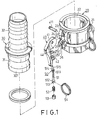
- a tube connecting device according to the present invention is shown to comprise a first tubular connector member 20, a second tubular connector member 30, a pair of press arms 40 and a pair of retaining units 50.
- the first connector member 20 has a receiving end portion 21 which has an appropriately-sized inner diameter and which confines a hollow receiving space 22 therein.
- Two opposite pairs of pivot ears 24 project outwardly from the receiving end portion 20.
- a radial opening 23 is formed between each pair of pivot ears 24.
- a retaining seat 25 projects outwardly from the receiving end portion 21 below each of the pairs of pivot ears 24.
- Each of the retaining seats 25 is formed with a vertical through-hole 251 and has a downwardly curving distal surface 252.
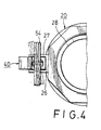
- a pair of locating projections 26 project outwardly and radially from the first connector member 20 and are disposed immediately below a respective one of the retaining seats 25.
- Each of the locating projections 26 has a distal face disposed a first predetermined distance (L1) from an axis of the through-hole 251.
- Two pairs of guard plates 27 extend radially and outwardly from the first connector member 20 such that the guard plates 27 of each pair are located on two sides of the respective retaining seat 25 and on two sides of the locating projection 26 which is immediately below the respective retaining seat 25.
- the first connector member 20 further has an opposite end portion 28 which is adapted to be connected to one end of a corresponding tube .
- the structural connection between the opposite end portion 28 and the corresponding tube is known in the art and will not be detailed herein.
- the second connector member 30 has an insert end portion 301 which extends into the hollow receiving space 22 confined by the receiving end portion 21 of the first connector member 20.
- the insert end portion 301 has an outer surface which is formed with an annular peripheral groove 31.
- the peripheral groove 31 has an inwardly curved inner end and is registered with the radial openings 23.
- the second connector member 30 further has an engaging end portion 32 which is adapted to be connected to one end of a corresponding tube (shown in phantom lines).
- the structural connection between the engaging end portion 32 and the corresponding tube is known in the art and will not be detailed herein.
- Each of the press arms 40 is provided between one of the pairs of pivot ears 24 and has one end which is formed with a cam face 41 and which is mounted pivotally to the pivot ears 24 via a pivot pin 411.
- Each of the press arms 40 further has an inner side which is formed with a longitudinal positioning seat 42.
- the positioning seat 42 is formed with an axial positioning bore 44 which is aligned with the through-hole 251 in a respective one of the retaining seats 25 when the press arm 40 is pivoted downwardly to a locking position.
- the positioning seat 42 has an inner side face 421 disposed a second predetermined distance (L2) from an axis of the positioning bore 44.
- the second predetermined distance (L2) is equal to the first predetermined distance (L1) so that the inner side face 421 of the positioning seat 42 abuts the distal face of the locating projection 26 below the corresponding retaining seat 25 when the press arm 40 is in the locking position.
- Each of the retaining units 50 includes a positioning rod 51 which is provided slidably in the positioning bore 44 of a respective positioning seat 42.
- the positioning rod 51 has an intermediate portion which is formed with a radial flange 511 and first and second end portions 514,512 which extend out of the positioning bore 44.
- a biasing unit such as a compression spring 52, is disposed in the positioning bore 44 around the positioning rod 51.
- the compression spring 52 has one end which abuts against the radial flange 511.
- a locking ring 53 is provided around the positioning rod 51 and is press-fitted in a second end of the positioning bore 44, which second end is opposite to the first end thereof.
- the locking ring 53 abuts against the other end of the compression spring 52, thereby enabling the compression spring 52 to bias the positioning rod 51 to permit extension of the first end portion 514 of the positioning rod 51 normally out of the positioning bore 44.
- the first end portion 514 of each of the positioning rods 51 has a tip which is formed with an inclined surface 515 that abuts the distal surface 252 of the respective retaining seat 25 when the respective press arm 40 is being pivoted to the locking position.
- the second end portion 512 of each of the positioning rods 51 is formed with an elongated slot 513 which is transverse to an axis of the positioning rod 51.
- a pull ring 54 which is formed from a flexible wire material into a plurality of concentric turns, extends through the slot 513 in the second end portion 512 of a respective one of the positioning rods 51.
- Each of the pull rings 54 has one side adjacent to the inner side of the respective press arm 40.
- the positioning rods 51 are provided slidably in the positioning bore 44 of the respective positioning seat 25.
- the biasing unit 52 is disposed in the positioning bore 44 around the positioning rod 51.
- the locking ring 53 is provided around the positioning rod 51 and is press-fitted in the second end of the positioning bore 44 such that the positioning rod 51 is movable axially in the positioning bore 44. It should be noted that the second end portion 512 of each of the positioning rods 51 is flat.
- the pull rings 54 then extend respectively through the slots 513. Each of the pull rings 54 can be pulled in a direction along the axis of the positioning rod 51 so as to cause axial movement of the latter.
- the rotation of the pull ring 54 about the axis of the positioning rod 51 is restricted so as to limit rotation of the positioning rod 51 in the positioning bore 44, thereby preventing the inclined surface 515 of the positioning rod 51 from being misplaced relative to the distal surface 252 of the respective retaining seat 25 when the respective press arm 40 is being pivoted to the locking position.
- each positioning rod 51 eventually abuts against the distal surface 252 of the respective retaining seat 25.
- the positioning rod 51 is retracted gradually into the positioning bore 44 against the action of the compression spring 52, as best illustrated in Fig. 5.
- the distal surface 252 ceases to exert pressure on the first end portion 514 of the positioning rod 51.
- the first end portion 514 of the positioning rod 51 extends into the through-hole 251 at this stage, thus retaining the press arms 40 on the first connector member 20 so as to prevent untimely movement of the former. Tight engagement between the first and second connector members 20,30 is therefore ensured.
- the inner side face 421 of each of the positioning seats 42 abuts against the distal face of the respective locating projection 26 when the respective press arm 40 is in the locking position. Therefore, damage and deformation of the positioning rods 51 and the retaining seats 25 can be prevented when a moving object strikes the press arms 40 while the latter are in the locking position.
- the pull rings 54 are pulled downwardly so as to retract the positioning rods 51 into the respective positioning bore 44 against the action of the compression springs 52, thereby disengaging the first end portion 514 from the respective retaining seat 25.
- the press arms 40 are then pivoted upwardly to an unlocking position until the cam faces 42 of the press arms 40 cease to extend into the peripheral groove 31 in the second connector member 30.
- the second connector member 30 can be removed from the first connector member 20 at this stage.
Landscapes
- Engineering & Computer Science (AREA)
- General Engineering & Computer Science (AREA)
- Mechanical Engineering (AREA)
- Quick-Acting Or Multi-Walled Pipe Joints (AREA)
- Mechanical Coupling Of Light Guides (AREA)
- Non-Disconnectible Joints And Screw-Threaded Joints (AREA)
- Earth Drilling (AREA)
- Joints With Sleeves (AREA)
- External Artificial Organs (AREA)
Priority Applications (7)
| Application Number | Priority Date | Filing Date | Title |
|---|---|---|---|
| AT95107272T ATE203806T1 (de) | 1995-05-12 | 1995-05-12 | Rohrverbindung |
| DK95107272T DK0742402T3 (da) | 1995-05-12 | 1995-05-12 | Rørforbindelsesindretning |
| DE69521986T DE69521986T2 (de) | 1995-05-12 | 1995-05-12 | Rohrverbindung |
| ES95107272T ES2158917T3 (es) | 1995-05-12 | 1995-05-12 | Dispositivo conector de tubos. |
| EP95107272A EP0742402B1 (en) | 1995-05-12 | 1995-05-12 | Tube connecting device |
| PT95107272T PT742402E (pt) | 1995-05-12 | 1995-05-12 | Dispositivo para a ligacao de tubos |
| GR20010401470T GR3036609T3 (en) | 1995-05-12 | 2001-09-12 | Tube connecting device |
Applications Claiming Priority (1)
| Application Number | Priority Date | Filing Date | Title |
|---|---|---|---|
| EP95107272A EP0742402B1 (en) | 1995-05-12 | 1995-05-12 | Tube connecting device |
Publications (2)
| Publication Number | Publication Date |
|---|---|
| EP0742402A1 EP0742402A1 (en) | 1996-11-13 |
| EP0742402B1 true EP0742402B1 (en) | 2001-08-01 |
Family
ID=8219251
Family Applications (1)
| Application Number | Title | Priority Date | Filing Date |
|---|---|---|---|
| EP95107272A Expired - Lifetime EP0742402B1 (en) | 1995-05-12 | 1995-05-12 | Tube connecting device |
Country Status (7)
| Country | Link |
|---|---|
| EP (1) | EP0742402B1 (da) |
| AT (1) | ATE203806T1 (da) |
| DE (1) | DE69521986T2 (da) |
| DK (1) | DK0742402T3 (da) |
| ES (1) | ES2158917T3 (da) |
| GR (1) | GR3036609T3 (da) |
| PT (1) | PT742402E (da) |
Cited By (2)
| Publication number | Priority date | Publication date | Assignee | Title |
|---|---|---|---|---|
| KR101300311B1 (ko) * | 2012-03-09 | 2013-08-28 | 워터슨 첸 | 캠-로크 구동 장치 |
| KR20210085471A (ko) * | 2019-12-30 | 2021-07-08 | 한국항공우주연구원 | 발사체용 커넥팅 장치 |
Families Citing this family (4)
| Publication number | Priority date | Publication date | Assignee | Title |
|---|---|---|---|---|
| US5988693A (en) | 1997-07-31 | 1999-11-23 | Campbell Fittings, Inc. | Safety locking coupling assembly |
| EP0898110A1 (fr) * | 1997-08-22 | 1999-02-24 | Perolo S.A. | Dispositif de manoeuvre et de verrouillage d'un coupleur femelle et coupleur femelle équipé de ce dispositif |
| ITTO20090061A1 (it) * | 2009-02-03 | 2009-05-05 | Roberto Ravetti | Valvola piatta dotata di sistema di serraggio rapido |
| US8662540B2 (en) | 2011-11-02 | 2014-03-04 | Philip C. Whitener | Quick tube connector |
Family Cites Families (4)
| Publication number | Priority date | Publication date | Assignee | Title |
|---|---|---|---|---|
| US2518026A (en) * | 1946-07-17 | 1950-08-08 | John T Krapp | Coupling |
| US3976313A (en) * | 1975-06-13 | 1976-08-24 | Edmund H. Waszkiewicz | Lauffen safety locking device for a coupling |
| US4295670A (en) * | 1980-06-11 | 1981-10-20 | Dixon Valve & Coupling Co. | Quick-disconnect cam locking safety coupling |
| DE9303353U1 (de) * | 1993-03-08 | 1993-05-06 | Chen, Waterson, Ta-Li Hsiang, Taichung | Rohrverbindungsvorrichtung |
-
1995
- 1995-05-12 DE DE69521986T patent/DE69521986T2/de not_active Expired - Lifetime
- 1995-05-12 PT PT95107272T patent/PT742402E/pt unknown
- 1995-05-12 EP EP95107272A patent/EP0742402B1/en not_active Expired - Lifetime
- 1995-05-12 DK DK95107272T patent/DK0742402T3/da active
- 1995-05-12 AT AT95107272T patent/ATE203806T1/de not_active IP Right Cessation
- 1995-05-12 ES ES95107272T patent/ES2158917T3/es not_active Expired - Lifetime
-
2001
- 2001-09-12 GR GR20010401470T patent/GR3036609T3/el not_active IP Right Cessation
Cited By (2)
| Publication number | Priority date | Publication date | Assignee | Title |
|---|---|---|---|---|
| KR101300311B1 (ko) * | 2012-03-09 | 2013-08-28 | 워터슨 첸 | 캠-로크 구동 장치 |
| KR20210085471A (ko) * | 2019-12-30 | 2021-07-08 | 한국항공우주연구원 | 발사체용 커넥팅 장치 |
Also Published As
| Publication number | Publication date |
|---|---|
| EP0742402A1 (en) | 1996-11-13 |
| DE69521986D1 (de) | 2001-09-06 |
| GR3036609T3 (en) | 2001-12-31 |
| ES2158917T3 (es) | 2001-09-16 |
| DE69521986T2 (de) | 2001-11-15 |
| PT742402E (pt) | 2001-12-28 |
| ATE203806T1 (de) | 2001-08-15 |
| DK0742402T3 (da) | 2001-10-22 |
Similar Documents
| Publication | Publication Date | Title |
|---|---|---|
| US5435604A (en) | Tube connecting device | |
| US6015168A (en) | Pivotal lock for coupling cam arms | |
| EP0926422B1 (en) | Pipe coupling socket | |
| US4550967A (en) | Electrical connector member | |
| EP0615090B1 (en) | Tube connecting device | |
| EP0679829B1 (en) | Coupling apparatus | |
| US5791694A (en) | Lock for coupling cam arms | |
| US7452006B2 (en) | Pipe joint and socket for pipe joint | |
| US6086400A (en) | Self-locking cable connector coupling | |
| US6186561B1 (en) | Retainer for piping connector | |
| US3969033A (en) | Torque transmitting coupling | |
| US20040051313A1 (en) | Feed pipe coupling for a pressurised fluid system | |
| EP0193438A1 (fr) | Raccord rapide à verrouillage par verrou à déplacement radial | |
| EP0742402B1 (en) | Tube connecting device | |
| US5690503A (en) | Connector lock structure | |
| JPH0772599B2 (ja) | カップリングフィッティング | |
| US5088853A (en) | Connector | |
| US20020022397A1 (en) | Connector | |
| US4530559A (en) | Locking means for a plug and receptacle connector | |
| US7086886B2 (en) | Reinforced locking connector | |
| CA3100586C (en) | Coupler for interconnecting externally splined power take off shaft of prime mover and driveline of implement | |
| JP7126170B2 (ja) | 差込式結合継手 | |
| EP1030993B1 (en) | Quick-action coupling | |
| US4811653A (en) | Vacuum booster enclosure | |
| JP7376099B2 (ja) | 差込式結合継手の差し具及び差込式結合継手 |
Legal Events
| Date | Code | Title | Description |
|---|---|---|---|
| PUAI | Public reference made under article 153(3) epc to a published international application that has entered the european phase |
Free format text: ORIGINAL CODE: 0009012 |
|
| AK | Designated contracting states |
Kind code of ref document: A1 Designated state(s): AT BE CH DE DK ES FR GB GR IE IT LI LU MC NL PT SE |
|
| 17P | Request for examination filed |
Effective date: 19970107 |
|
| 17Q | First examination report despatched |
Effective date: 19990217 |
|
| GRAG | Despatch of communication of intention to grant |
Free format text: ORIGINAL CODE: EPIDOS AGRA |
|
| GRAG | Despatch of communication of intention to grant |
Free format text: ORIGINAL CODE: EPIDOS AGRA |
|
| GRAH | Despatch of communication of intention to grant a patent |
Free format text: ORIGINAL CODE: EPIDOS IGRA |
|
| GRAH | Despatch of communication of intention to grant a patent |
Free format text: ORIGINAL CODE: EPIDOS IGRA |
|
| GRAA | (expected) grant |
Free format text: ORIGINAL CODE: 0009210 |
|
| AK | Designated contracting states |
Kind code of ref document: B1 Designated state(s): AT BE CH DE DK ES FR GB GR IE IT LI LU MC NL PT SE |
|
| REF | Corresponds to: |
Ref document number: 203806 Country of ref document: AT Date of ref document: 20010815 Kind code of ref document: T |
|
| REG | Reference to a national code |
Ref country code: CH Ref legal event code: EP |
|
| REG | Reference to a national code |
Ref country code: CH Ref legal event code: NV Representative=s name: MICHELI & CIE INGENIEURS-CONSEILS |
|
| REG | Reference to a national code |
Ref country code: IE Ref legal event code: FG4D |
|
| REF | Corresponds to: |
Ref document number: 69521986 Country of ref document: DE Date of ref document: 20010906 |
|
| REG | Reference to a national code |
Ref country code: ES Ref legal event code: FG2A Ref document number: 2158917 Country of ref document: ES Kind code of ref document: T3 |
|
| REG | Reference to a national code |
Ref country code: DK Ref legal event code: T3 |
|
| ET | Fr: translation filed | ||
| REG | Reference to a national code |
Ref country code: PT Ref legal event code: SC4A Free format text: AVAILABILITY OF NATIONAL TRANSLATION Effective date: 20010914 |
|
| REG | Reference to a national code |
Ref country code: GB Ref legal event code: IF02 |
|
| PLBE | No opposition filed within time limit |
Free format text: ORIGINAL CODE: 0009261 |
|
| STAA | Information on the status of an ep patent application or granted ep patent |
Free format text: STATUS: NO OPPOSITION FILED WITHIN TIME LIMIT |
|
| 26N | No opposition filed | ||
| PGFP | Annual fee paid to national office [announced via postgrant information from national office to epo] |
Ref country code: LU Payment date: 20080526 Year of fee payment: 14 Ref country code: DK Payment date: 20080526 Year of fee payment: 14 |
|
| PGFP | Annual fee paid to national office [announced via postgrant information from national office to epo] |
Ref country code: AT Payment date: 20080521 Year of fee payment: 14 |
|
| PGFP | Annual fee paid to national office [announced via postgrant information from national office to epo] |
Ref country code: MC Payment date: 20080521 Year of fee payment: 14 Ref country code: PT Payment date: 20080509 Year of fee payment: 14 |
|
| PGFP | Annual fee paid to national office [announced via postgrant information from national office to epo] |
Ref country code: GR Payment date: 20080523 Year of fee payment: 14 |
|
| REG | Reference to a national code |
Ref country code: PT Ref legal event code: MM4A Free format text: LAPSE DUE TO NON-PAYMENT OF FEES Effective date: 20091112 |
|
| PG25 | Lapsed in a contracting state [announced via postgrant information from national office to epo] |
Ref country code: MC Free format text: LAPSE BECAUSE OF NON-PAYMENT OF DUE FEES Effective date: 20090531 |
|
| REG | Reference to a national code |
Ref country code: DK Ref legal event code: EBP |
|
| PG25 | Lapsed in a contracting state [announced via postgrant information from national office to epo] |
Ref country code: AT Free format text: LAPSE BECAUSE OF NON-PAYMENT OF DUE FEES Effective date: 20090512 |
|
| PG25 | Lapsed in a contracting state [announced via postgrant information from national office to epo] |
Ref country code: PT Free format text: LAPSE BECAUSE OF NON-PAYMENT OF DUE FEES Effective date: 20091112 |
|
| PG25 | Lapsed in a contracting state [announced via postgrant information from national office to epo] |
Ref country code: DK Free format text: LAPSE BECAUSE OF NON-PAYMENT OF DUE FEES Effective date: 20090531 |
|
| PG25 | Lapsed in a contracting state [announced via postgrant information from national office to epo] |
Ref country code: GR Free format text: LAPSE BECAUSE OF NON-PAYMENT OF DUE FEES Effective date: 20091202 |
|
| PG25 | Lapsed in a contracting state [announced via postgrant information from national office to epo] |
Ref country code: LU Free format text: LAPSE BECAUSE OF NON-PAYMENT OF DUE FEES Effective date: 20090512 |
|
| PGFP | Annual fee paid to national office [announced via postgrant information from national office to epo] |
Ref country code: CH Payment date: 20120531 Year of fee payment: 18 Ref country code: IE Payment date: 20120508 Year of fee payment: 18 |
|
| PGFP | Annual fee paid to national office [announced via postgrant information from national office to epo] |
Ref country code: SE Payment date: 20120508 Year of fee payment: 18 Ref country code: FR Payment date: 20120615 Year of fee payment: 18 |
|
| PGFP | Annual fee paid to national office [announced via postgrant information from national office to epo] |
Ref country code: IT Payment date: 20120522 Year of fee payment: 18 |
|
| PGFP | Annual fee paid to national office [announced via postgrant information from national office to epo] |
Ref country code: ES Payment date: 20120629 Year of fee payment: 18 |
|
| PGFP | Annual fee paid to national office [announced via postgrant information from national office to epo] |
Ref country code: GB Payment date: 20130514 Year of fee payment: 19 Ref country code: DE Payment date: 20130514 Year of fee payment: 19 |
|
| PGFP | Annual fee paid to national office [announced via postgrant information from national office to epo] |
Ref country code: NL Payment date: 20130524 Year of fee payment: 19 |
|
| PGFP | Annual fee paid to national office [announced via postgrant information from national office to epo] |
Ref country code: BE Payment date: 20130626 Year of fee payment: 19 |
|
| REG | Reference to a national code |
Ref country code: CH Ref legal event code: PL |
|
| REG | Reference to a national code |
Ref country code: SE Ref legal event code: EUG |
|
| PG25 | Lapsed in a contracting state [announced via postgrant information from national office to epo] |
Ref country code: CH Free format text: LAPSE BECAUSE OF NON-PAYMENT OF DUE FEES Effective date: 20130531 Ref country code: SE Free format text: LAPSE BECAUSE OF NON-PAYMENT OF DUE FEES Effective date: 20130513 Ref country code: LI Free format text: LAPSE BECAUSE OF NON-PAYMENT OF DUE FEES Effective date: 20130531 |
|
| REG | Reference to a national code |
Ref country code: IE Ref legal event code: MM4A |
|
| PG25 | Lapsed in a contracting state [announced via postgrant information from national office to epo] |
Ref country code: IT Free format text: LAPSE BECAUSE OF NON-PAYMENT OF DUE FEES Effective date: 20130512 |
|
| REG | Reference to a national code |
Ref country code: FR Ref legal event code: ST Effective date: 20140131 |
|
| PG25 | Lapsed in a contracting state [announced via postgrant information from national office to epo] |
Ref country code: IE Free format text: LAPSE BECAUSE OF NON-PAYMENT OF DUE FEES Effective date: 20130512 |
|
| PG25 | Lapsed in a contracting state [announced via postgrant information from national office to epo] |
Ref country code: FR Free format text: LAPSE BECAUSE OF NON-PAYMENT OF DUE FEES Effective date: 20130531 |
|
| REG | Reference to a national code |
Ref country code: ES Ref legal event code: FD2A Effective date: 20140606 |
|
| PG25 | Lapsed in a contracting state [announced via postgrant information from national office to epo] |
Ref country code: ES Free format text: LAPSE BECAUSE OF NON-PAYMENT OF DUE FEES Effective date: 20130513 |
|
| REG | Reference to a national code |
Ref country code: DE Ref legal event code: R119 Ref document number: 69521986 Country of ref document: DE |
|
| REG | Reference to a national code |
Ref country code: NL Ref legal event code: V1 Effective date: 20141201 |
|
| GBPC | Gb: european patent ceased through non-payment of renewal fee |
Effective date: 20140512 |
|
| REG | Reference to a national code |
Ref country code: DE Ref legal event code: R119 Ref document number: 69521986 Country of ref document: DE Effective date: 20141202 |
|
| PG25 | Lapsed in a contracting state [announced via postgrant information from national office to epo] |
Ref country code: NL Free format text: LAPSE BECAUSE OF NON-PAYMENT OF DUE FEES Effective date: 20141201 |
|
| PG25 | Lapsed in a contracting state [announced via postgrant information from national office to epo] |
Ref country code: DE Free format text: LAPSE BECAUSE OF NON-PAYMENT OF DUE FEES Effective date: 20141202 |
|
| PG25 | Lapsed in a contracting state [announced via postgrant information from national office to epo] |
Ref country code: GB Free format text: LAPSE BECAUSE OF NON-PAYMENT OF DUE FEES Effective date: 20140512 |
|
| PG25 | Lapsed in a contracting state [announced via postgrant information from national office to epo] |
Ref country code: BE Free format text: LAPSE BECAUSE OF NON-PAYMENT OF DUE FEES Effective date: 20140531 |