EP0742425B1 - Vorrichtung zum Aufbringen genau dosierter Mengen eines viskosen Mediums auf Auflageflächen - Google Patents
Vorrichtung zum Aufbringen genau dosierter Mengen eines viskosen Mediums auf Auflageflächen Download PDFInfo
- Publication number
- EP0742425B1 EP0742425B1 EP96201135A EP96201135A EP0742425B1 EP 0742425 B1 EP0742425 B1 EP 0742425B1 EP 96201135 A EP96201135 A EP 96201135A EP 96201135 A EP96201135 A EP 96201135A EP 0742425 B1 EP0742425 B1 EP 0742425B1
- Authority
- EP
- European Patent Office
- Prior art keywords
- plate
- dosing
- hole
- backing plate
- die
- Prior art date
- Legal status (The legal status is an assumption and is not a legal conclusion. Google has not performed a legal analysis and makes no representation as to the accuracy of the status listed.)
- Expired - Lifetime
Links
Images
Classifications
-
- B—PERFORMING OPERATIONS; TRANSPORTING
- B23—MACHINE TOOLS; METAL-WORKING NOT OTHERWISE PROVIDED FOR
- B23K—SOLDERING OR UNSOLDERING; WELDING; CLADDING OR PLATING BY SOLDERING OR WELDING; CUTTING BY APPLYING HEAT LOCALLY, e.g. FLAME CUTTING; WORKING BY LASER BEAM
- B23K3/00—Tools, devices or special appurtenances for soldering, e.g. brazing, or unsoldering, not specially adapted for particular methods
- B23K3/06—Solder feeding devices; Solder melting pans
- B23K3/0607—Solder feeding devices
-
- G—PHYSICS
- G01—MEASURING; TESTING
- G01F—MEASURING VOLUME, VOLUME FLOW, MASS FLOW OR LIQUID LEVEL; METERING BY VOLUME
- G01F11/00—Apparatus requiring external operation adapted at each repeated and identical operation to measure and separate a predetermined volume of fluid or fluent solid material from a supply or container, without regard to weight, and to deliver it
- G01F11/10—Apparatus requiring external operation adapted at each repeated and identical operation to measure and separate a predetermined volume of fluid or fluent solid material from a supply or container, without regard to weight, and to deliver it with measuring chambers moved during operation
- G01F11/12—Apparatus requiring external operation adapted at each repeated and identical operation to measure and separate a predetermined volume of fluid or fluent solid material from a supply or container, without regard to weight, and to deliver it with measuring chambers moved during operation of the valve type, i.e. the separating being effected by fluid-tight or powder-tight movements
- G01F11/14—Apparatus requiring external operation adapted at each repeated and identical operation to measure and separate a predetermined volume of fluid or fluent solid material from a supply or container, without regard to weight, and to deliver it with measuring chambers moved during operation of the valve type, i.e. the separating being effected by fluid-tight or powder-tight movements wherein the measuring chamber reciprocates
- G01F11/16—Apparatus requiring external operation adapted at each repeated and identical operation to measure and separate a predetermined volume of fluid or fluent solid material from a supply or container, without regard to weight, and to deliver it with measuring chambers moved during operation of the valve type, i.e. the separating being effected by fluid-tight or powder-tight movements wherein the measuring chamber reciprocates for liquid or semiliquid
Definitions
- the invention relates to a device for applying precisely metered Amounts of a viscous medium on contact surfaces.
- JP 2-301184 consists of a horizontally arranged metering plate, which has an opening in which there is a form-fit stamp that can be moved in the vertical direction.
- the stamp is in a middle position such that between the top of the stamp and the top of the metering plate gives a cavity.
- This is located on the top of the metering plate to the side of the opening dosing viscous medium. This is done by means of a parallel to the top of the Metering plate working squeegee device in the cavity between the top of the stamp and the top of the dosing plate.
- the method has some disadvantages.
- a dose of the viscous medium using the stamp is only possible in the vertical direction from bottom to top, whereby the possible uses of this method are severely restricted. So is it is not possible to put precisely metered amounts of the viscous medium on it support surfaces extending vertically or on other components apply hidden contact surfaces.
- the dosing amount in this process is from depending on the current viscosity of the medium.
- the counter plate and the metering plate are displaced relative to one another in such a way that the opening in the counter plate and the opening in the metering plate do not overlap.
- the viscous medium applied to the top of the metering plate is introduced into the opening of the metering plate by means of the doctor device.
- the dosing quantity depends on the cross section and the height of the opening and can be varied as required by changing these parameters.
- the dosing plate and the counter plate are shifted against each other in such a way that the opening of the dosing plate filled with the viscous medium comes to rest exactly above the opening of the counter plate.
- the inside diameter of the opening in the metering plate corresponds to the inside diameter of the hollow tube inside, which is located in the opening in the counterplate.
- the stamp is inserted into the opening in the metering plate and then into the tube up to the end of the tube. This pushes the viscous medium out of the tube onto the support surface.
- the dosing accuracy of this device according to the invention is significantly increased, particularly with small dosing quantities.
- the diameter of the tube and corresponding to that of the stamp can be chosen to be very small. It is not necessary to vary it with different dosage amounts. Rather, the dosing quantity can be varied via the height of the opening in the dosing plate. Due to the small diameter of the stamp, the amount of viscous medium that sticks to the stamp when the stamp is withdrawn from the support surface is very small. In addition, when the stamp is withdrawn, there is a dripping effect on the edge of the tube.
- the dosing accuracy that can be achieved with this device is on the order of approximately 1 mm 3 . Another advantage of this device is that it can be dosed both from the bottom up and from the top down.
- the flexible design of the tube and the stamp enables the viscous medium can also be applied to vertical or inclined support surfaces.
- a device under assembly e.g. a magnetic tape cassette device
- exactly dosed quantities of fat are applied to the contact surfaces, so with the
- the device according to the invention has support surfaces distributed almost arbitrarily in the device to reach.
- a further advantageous embodiment of the invention is characterized in that a guide plate is provided above the metering plate, which has a perforation for each stamp to guide the stamp.
- the guide plate is an aid to enable extensive automation of the dosing process.
- a further advantageous embodiment of the invention is characterized in that in the Breakthrough of the guide plate, a sleeve is attached, the inner diameter of which Diameter of the through-hole corresponds to the metering plate and that a sleeve end is form-fitting rests on the top of the dosing plate.
- a further advantageous embodiment of the invention is characterized in that the Stamp is arranged on an upper plate, which is perpendicular to the top and bottom of the Dosing plate and the counter plate is movable.
- the top plate is an aid to one extensive automation of the dosing process enable.
- it is possible to add several stamps to the top plate fasten which, when the top plate is shut down, is arranged accordingly Breakthroughs in the guide plate and the metering plate and subsequently in appropriately arranged tubes are inserted. This will make it simultaneous application of precisely metered quantities on several contact surfaces possible.
- top plate, guide plate, metering plate and Counter plate form an overall unit, which, guided by a guide frame, is movable perpendicular to the top and bottom of the plates.
- the entire unit Before inserting the stamp, the entire unit is lowered in such a way that a Tube end comes to rest over the support surface. After that the stamp by lowering the top plate into the opening in the metering plate and subsequently inserted into the tube into an end position, and the viscous Medium is pressed onto the support surface, the guide plate, the Dosing plate and the counter plate their relative position to the guide frame maintained. The entire unit is then started up, the stamp and the top plate remains in the end position. This prevents a part of the viscous medium when the stamp is withdrawn from the contact surface in the hollow tube is suctioned off. Only then is the stamp accepted Raising the top plate out of the tube and breakthrough the Dosing plate moved out, the guide plate, the dosing plate and the Counterplate maintain its relative position to the guide frame.
- the device according to the invention can preferably be used for Apply a precisely metered amount of adhesive paste to a circuit board Fixing a component, to apply a precisely metered amount of one Solder paste on a circuit board or to apply grease to grease points Cassette deck.
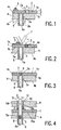
- FIG. 1 shows a first embodiment of a dosing device at different times during the dosing process. To make the display clearer, only parts of the metering device are shown for the individual times.
- a part of a metering device shown in FIG. 1 has a metering plate 1 with an upper side 1a, a lower side 1b and a plate thickness H.
- a circular opening 2 with an opening diameter D and an opening wall 2a.
- the underside 1b of the metering plate 1 rests on a counter plate 4 which has an upper side 4a, an underside 4b and an opening 5 with opening walls 5a.
- An internally hollow tube 6 is fastened in the opening 5, said tube having inner walls 6a and the inside diameter E of which is equal to the diameter D of the opening 2 of the metering plate 1.
- the metering plate 1 is displaceable in the horizontal direction with respect to the counter plate 4. In the position of the metering plate 1 shown in FIG. 1, it is arranged such that the opening 2 of the metering plate 1 and the opening 5 of the counter plate 4 do not overlap.
- the position of the metering plate 1 shown in FIG. 1 also takes this in FIG. 2 on.
- an indicated doctor device 7 can be seen, which is parallel to the top 1a of the dosing plate 1 works and by means of which a dosing quantity 8 of the medium 3 to be metered into the opening 2 of the metering plate 1 has been.
- the introduced dosage 8 is of the diameter D of the Breakthrough 2 of the metering plate 1 and of the height H of the metering plate 1 dependent.
- the dosing quantity 8 can be varied as desired.
- the Inner diameter E of the tube 6 must be adjusted accordingly.
- metering plate 1 is opposite the position shown in Figs. 1 and 2 have been moved such that the dosing quantity 8 of the viscous medium 3 filled opening 2 of the metering plate 1 exactly over the opening 5 of the Counter plate 4 has come to a standstill. So that the inner walls 2a of the Opening 2 of the metering plate 1 with the inner walls 6a of the opening 5 attached tube 6.
- the metering plate 1 takes the position shown in Fig. 3 opposite the Counter plate 4 a.
- a guide plate 9 is located above the metering plate 1 arranged, which has an opening 10 with opening walls 10a.
- the opening 10 of the guide plate 9 has an internally hollow sleeve 11 attached, which has an inner wall 11a and an outer wall 11b.
- the inner diameter F of the sleeve 11 corresponds to the diameter D of the opening 2 the dosing plate 1 and the inner diameter E of the tube 6.
- Die Guide plate 9 with the sleeve 11 is arranged such that the inner wall 11a Sleeve 11, the breakthrough wall 2a of the opening 2 of the metering plate 1 and the The inner wall 6a of the tube 6 is aligned.
- the breakthrough 2 and that A stamp 12 is inserted into tube 6.
- the outside diameter G of this Stamp 12 corresponds to the inner diameter F of the sleeve 11, the diameter D. of the opening 2 and the inner diameter E of the tube 6.
- Fig. 5 is a dosing device in parts as a further embodiment shown, which has a counter plate 14 in which there are two openings 15 and 16 are located.
- these openings 15 and 16 are two flexible tubes 17 and 18 attached, in which there are also two flexible, in the tubes 17 and 18 movable stamps 19 and 20 are located.
- the tube ends 17a and 18a of the flexible tubes 17 and 18 are located directly above contact surfaces 22 and 23 of a device 24.
- the contact surfaces 22 and 23 could e.g. to be greased Surfaces in a magnetic tape cassette device or solder pads on a circuit board.
- dosing quantities 25 and 26 are viscous Medium from the tubes 17 and 18 applied to the support surfaces 22 and 23 Service.
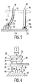
- FIG. 6 shows a basic functional illustration of a metering device, which automation of the dosing process. It has a top plate 30 a guide plate 31, a metering plate 32 and a counter plate 33. At the Upper plate 30, three stamps 34, 35 and 36 are attached. By means of this stamp 34, 35 and 36 is intended to be a dosing amount of a viscous medium, not shown Tubes 37, 38 and 39 on support surfaces 40, 41 and 42 of a device 43 be pressed. The tubes 37, 38 and 39 are not shown in FIG Breakthroughs of the counter plate 33. First, the top plate 30, the Guide plate 31, the metering plate 32 and the counter plate 33 non-positively locked together.
Landscapes
- Physics & Mathematics (AREA)
- Fluid Mechanics (AREA)
- General Physics & Mathematics (AREA)
- Engineering & Computer Science (AREA)
- Mechanical Engineering (AREA)
- Coating Apparatus (AREA)
Description
- einer mindestens einen Durchbruch aufweisenden Gegenplatte mit einer Oberseite und einer Unterseite,
- einer mindestens einen Durchbruch aufweisenden Dosierplatte mit einer Oberseite und einer Unterseite, wobei die Unterseite der Dosierplatte auf der Oberseite der Gegenplatte aufliegt und wobei es möglich ist, die relative Lage zwischen der Gegenplatte und der Dosierplatte durch ein Verschieben von Dosierplatte oder Gegenplatte zu verändern,
- je Durchbruch der Gegenplatte einen an innen hohlen biegsamen Röhrchen, das aus der Gegenplatte herausragt und dessen Außenwand an einem Röhrchenende mit der Durchbruchswand des Durchbruchs der Gegenplatte formschlüsssig verbunden ist,
- je Durchbruch der Gegenplatte einem biegsamen Stempel, der durch die Durchbrüche der Dosierplatte und der Gegenplatte und durch das innen hohle Röhrchen einschiebbar ist,
- einer parallel zu der Oberseite der Dosierplatte arbeitenden Rakeleinrichtung, mittels derer ein viskoses Medium in den Durchbruch der Dosierplatte eingebracht werden kann.
Die Führungsplatte ist ein Hilfsmittel, um eine weitgehende Automatisierung des Dosiervorganges zu ermöglichen.
Ein in Fig. 1 dargestellter Teil einer Dosiervorrichtung weist eine Dosierplatte 1 mit einer Oberseite 1a, einer Unterseite 1b sowie einer Plattendicke H auf. In der Dosierplatte 1 befindet sich ein kreisrunder Durchbruch 2 mit einem Durchbruchsdurchmesser D und einer Durchbruchswand 2a. Auf der Oberseite 1a der Dosierplatte 1 befindet sich seitlich des Durchbruchs 2 ein zu dosierendes viskoses Medium 3. Die Unterseite 1b der Dosierplatte 1 liegt auf einer Gegenplatte 4 auf, welche eine Oberseite 4a, eine Unterseite 4b sowie einen Durchbruch 5 mit Durchbruchswänden 5a aufweist. In dem Durchbruch 5 ist ein innen hohles Röhrchen 6 befestigt, welches Innenwände 6a aufweist und dessen Innendurchmesser E gleich dem Durchmesser D des Durchbruchs 2 der Dosierplatte 1 ist. Die Dosierplatte 1 ist gegenüber der Gegenplatte 4 in horizontaler Richtung verschiebbar. In der in Fig. 1 dargestellten Stellung der Dosierplatte 1 ist diese derart angeordnet, daß sich der Durchbruch 2 der Dosierplatte 1 und der Durchbruch 5 der Gegenplatte 4 nicht überdecken.
Claims (11)
- Vorrichtung zum Aufbringen genau dosierter Mengen eines viskosen Mediums (3) auf Auflageflächen (22, 23; 40, 41, 42), bestehend auseiner mindestens einen Durchbruch (5; 15, 16) aufweisenden Gegenplatte (4; 14; 33) mit einer Oberseite (4a) und einer Unterseite (4b),einer mindestens einen Durchbruch (2) aufweisenden Dosierplatte (1; 32) mit einer Oberseite (1a) und einer Unterseite (1b), wobei die Unterseite (1b) der Dosierplatte (1; 32) auf der Oberseite (4a) der Gegenplatte (4; 14; 33) aufliegt und wobei es möglich ist, die relative Lage zwischen der Gegenplatte (4; 14; 33) und der Dosierplatte (1; 32) durch ein Verschieben von Dosierplatte (1; 32) oder Gegenplatte (4; 14; 33) zu verändern,je Durchbruch (5; 15, 16) der Gegenplatte (4; 14; 33) einem innen hohlen, biegsamen Röhrchen (6; 17, 18; 37, 38, 39), das aus der Gegenplatte herausragt und dessen Außenwand (6b) an einem Röhrchenende mit der Durchbruchswand (5a) des Durchbruchs (5; 15, 16) der Gegenplatte (4; 14; 33) formschlüsssig verbunden ist,je Durchbruch (5; 15,16) der Gegenplatte (4; 14; 33) einem biegsamen Stempel (12; 19, 20; 34, 35, 36) der durch die Durchbrüche der Dosierplatte (1; 32) und der Gegenplatte (4; 14; 33) und durch das innen hohle Röhrchen (6; 17, 18; 37, 38, 39) einschiebbar ist,einer parallel zu der Oberseite (la) der Dosierplatte (1; 32) arbeitenden Rakeleinrichtung (7), mittels derer ein viskoses Medium (3) in den Durchbruch (2) der Dosierplatte (1; 32) eingebracht werden kann.
- Vorrichtung nach Anspruch 1 oder 2, dadurch gekennzeichnet, daß oberhalb der Dosierplatte (1; 32) eine Führungsplatte (9; 31) vorgesehen ist, welche je Stempel (12; 19, 20; 34, 35, 36) einen Durchbruch (10) zur Führung des Stempels (12; 19, 20; 34, 35, 36) aufweist.
- Vorrichtung nach Anspruch 3, dadurch gekennzeichnet, daß in dem Durchbruch (10) der Führungsplatte (9; 31) eine Hülse (11) befestigt ist, deren Innendurchmesser dem Durchmesser des Durchbruchs (2) der Dosierplatte (1; 32) entspricht und daß ein Hülsenende formschlüssig auf der Oberseite (1a) der Dosierplatte (1; 32) aufliegt.
- Vorrichtung nach einem der Ansprüche 1 bis 4, dadurch gekennzeichnet, daß der Stempel (12; 19, 20; 34, 35, 36) an einer Oberplatte (30) angeordnet ist, welche senkrecht zu den Ober- und Unterseiten der Dosierplatte (1; 32) und der Gegenplatte (4; 14; 33) bewegbar ist.
- Vorrichtung nach einem der Ansprüche 1 bis 5, dadurch gekennzeichnet, daß Oberplatte (30), Führungsplatte (31), Dosierplatte (32) und Gegenplatte (33) eine Gesamteinheit bilden, die, geführt von einem Führungsgestell, senkrecht zu den Oberseiten und Unterseiten der Platten (30, 31, 32, 33) verfahrbar ist.
- Verfahren zum Aufbringen genau dosierter Mengen des viskosen Mediums (3) auf die Auflageflächen (22, 23; 40, 41, 42) mittels einer Vorrichtung nach einem der Ansprüche 1 bis 5 wobei zunächst die Gegenplatte (4; 14; 33) und die Dosierplatte (1; 32) derart gegeneinander verschoben werden, daß der Durchbruch (5; 15, 16) der Gegenplatte (4; 14; 33) und der Durchbruch (2) der Dosierplatte (1; 32) sich nicht überdecken, daß nachfolgend das viskose Medium (3) mittels der Rakeleinrichtung (7) in den Durchbruch (2) der Dosierplatte (1; 32) eingebracht wird, daß die Dosierplatte (1; 32) und die Gegenplatte (4; 14; 33) dann derart gegeneinander verschoben werden, daß der mit dem viskosen Medium (3) gefüllte Durchbruch (2) der Dosierplatte (1; 32) genau über dem Durchbruch (5; 15, 16) der Gegenplatte (4; 14; 33) zu stehen kommt, daß der biegsame Stempel (12; 19, 20; 34, 35, 36) in den Durchbruch der Dosierplatte (1; 32) und der Gegenplatte (4; 14; 33) und nachfolgend in das biegsame Röhrchen (6; 17, 18; 37, 38, 39) eingeschoben wird und daß das viskose Medium (3) mittels des biegsamen Stempels (12; 19, 20; 34, 35, 36) aus dem biegsamen Röhrchen (6; 17, 18; 37, 38, 39) auf die Auflageflächen (22, 23; 40, 41, 42) gedrückt wird.
- Verfahren nach Anspruch 6, dadurch gekennzeichnet, daß der Stempel (12; 19, 20; 34, 35, 36) beim Einschieben in den Durchbruch der Dosierplatte (1; 32) und der Gegenplatte (4; 14; 33) und beim Einschieben in das Röhrchen (9; 31) von den Durchbrüchen (10) der Führungsplatte(9; 31) geführt wird.
- Verfahren nach Anspruch 6 oder 7, dadurch gekennzeichnet, daß die Gesamteinheit vor dem Einschieben des Stempels (12; 19, 20; 34, 35, 36) derart abgesenkt wird, daß ein Ende des Röhrchens (6; 17, 18; 37, 38, 39) über den Auflageflächen (22, 23; 40, 41, 42) zu liegen kommt, daß dann der Stempel (12; 19, 20; 34, 35, 36) in die Durchbrüche der Dosierplatte (1; 32) und der Gegenplatte (4; 14; 33) und nachfolgend in das Röhrchen (6; 17, 18; 37, 38, 39) bis in eine Endposition eingeschoben wird und das viskose Medium (3) auf die Auflageflächen (22, 23; 40, 41, 42) drückt, und daß dann die Gesamteinheit mit dem sich in der Endposition befindenden Stempel (12; 19, 20; 34, 35, 36) angehoben wird.
- Verwendung der Vorrichtung oder des Verfahrens nach einem der Ansprüche 1 bis 8 zum Aufbringen einer genau dosierten Menge einer Klebepaste auf eine Leiterplatte zum Fixieren eines Bauelementes.
- Verwendung der Vorrichtung oder des Verfahrens nach einem der Ansprüche 1 bis 8 zum Aufbringen einer genau dosierten Menge einer Lötpaste auf eine Leiterplatte.
- Verwendung der Vorrichtung oder des Verfahrens nach einem der Ansprüche 1 bis 8 zum Aufbringen von Fett auf Fettpunkte eines Magnetbandkassettengerätes.
Applications Claiming Priority (2)
| Application Number | Priority Date | Filing Date | Title |
|---|---|---|---|
| DE19517342 | 1995-05-11 | ||
| DE19517342A DE19517342A1 (de) | 1995-05-11 | 1995-05-11 | Vorrichtung zum Aufbringen genau dosierter Mengen eines viskosen Mediums auf Auflageflächen |
Publications (2)
| Publication Number | Publication Date |
|---|---|
| EP0742425A1 EP0742425A1 (de) | 1996-11-13 |
| EP0742425B1 true EP0742425B1 (de) | 2003-08-06 |
Family
ID=7761684
Family Applications (1)
| Application Number | Title | Priority Date | Filing Date |
|---|---|---|---|
| EP96201135A Expired - Lifetime EP0742425B1 (de) | 1995-05-11 | 1996-05-07 | Vorrichtung zum Aufbringen genau dosierter Mengen eines viskosen Mediums auf Auflageflächen |
Country Status (4)
| Country | Link |
|---|---|
| US (1) | US5698257A (de) |
| EP (1) | EP0742425B1 (de) |
| JP (1) | JP3762477B2 (de) |
| DE (2) | DE19517342A1 (de) |
Citations (1)
| Publication number | Priority date | Publication date | Assignee | Title |
|---|---|---|---|---|
| US4021062A (en) * | 1974-03-15 | 1977-05-03 | Automatisation-Sogemo | Coupling assemblies |
Family Cites Families (3)
| Publication number | Priority date | Publication date | Assignee | Title |
|---|---|---|---|---|
| GB1089747A (en) * | 1964-06-02 | 1967-11-08 | Norton Co | Metering apparatus |
| JPH02301184A (ja) * | 1989-05-16 | 1990-12-13 | Matsushita Electric Ind Co Ltd | チップ部品への粘体微少塗布方法 |
| FR2692569B1 (fr) * | 1992-06-18 | 1996-08-30 | Valois | Procede et dispositif de remplissage d'un distributeur doseur de substance fluide. |
-
1995
- 1995-05-11 DE DE19517342A patent/DE19517342A1/de not_active Withdrawn
-
1996
- 1996-05-07 DE DE59610637T patent/DE59610637D1/de not_active Expired - Fee Related
- 1996-05-07 US US08/646,423 patent/US5698257A/en not_active Expired - Fee Related
- 1996-05-07 EP EP96201135A patent/EP0742425B1/de not_active Expired - Lifetime
- 1996-05-10 JP JP11620696A patent/JP3762477B2/ja not_active Expired - Fee Related
Patent Citations (1)
| Publication number | Priority date | Publication date | Assignee | Title |
|---|---|---|---|---|
| US4021062A (en) * | 1974-03-15 | 1977-05-03 | Automatisation-Sogemo | Coupling assemblies |
Also Published As
| Publication number | Publication date |
|---|---|
| DE19517342A1 (de) | 1996-11-14 |
| EP0742425A1 (de) | 1996-11-13 |
| JPH08299887A (ja) | 1996-11-19 |
| US5698257A (en) | 1997-12-16 |
| DE59610637D1 (de) | 2003-09-11 |
| JP3762477B2 (ja) | 2006-04-05 |
Similar Documents
| Publication | Publication Date | Title |
|---|---|---|
| DE69734775T2 (de) | Verfahren und vorrichtung zur ablagerung von einem viskosen produkt mit einer schablone | |
| DE3441984C2 (de) | ||
| DE60020090T2 (de) | Verfahren und vorrichtung zum auftragen von kugeln in die öffnungen eines kugelbehälters | |
| DE69517824T2 (de) | Verfahren und vorrichtung zum abgeben eines viskosen materials | |
| DE8621143U1 (de) | Vorrichtung zum Verbinden von Hohlprofilen | |
| DE69902861T2 (de) | Rakel für den Siebdruck und Siebdruckverfahren | |
| DE2716330A1 (de) | Verfahren zur bestueckung von schaltungsplatinen mit plaettchenfoermigen schaltungsbauteilen und vorrichtung zur durchfuehrung desselben | |
| DE60127108T2 (de) | Verfahren und vorrichtung zum aufbringen von viskosem oder pastösem material auf ein substrat | |
| DE2135772B2 (de) | Farbauftrag-dosiergeraet | |
| EP2009674B1 (de) | Vorrichtung zur Herstellung und Präsentation von Flüssigkeitsschichten | |
| DE60004659T2 (de) | Vorrichtung für das dosieren und die verteilung von hotmelt | |
| EP0742425B1 (de) | Vorrichtung zum Aufbringen genau dosierter Mengen eines viskosen Mediums auf Auflageflächen | |
| EP0324441B1 (de) | Einrichtung zum dosierten Auftragen von Klebstoff | |
| DE4209385C2 (de) | Preßmaschine für elektronische Komponenten des Chip-Types | |
| DE2226920C3 (de) | Verfahren und Vorrichtung zum Zusammenstellen von Faserschreibern | |
| EP0145900A2 (de) | Automatische Auftragvorrichtung für ein flüssiges oder pastöses Beschichtungsmaterial | |
| WO2010106151A1 (de) | Crimppresse | |
| DE4210650C2 (de) | Preßverfahren für elektronische Komponenten des Chip-Types | |
| DE3803528A1 (de) | Verfahren und vorrichtung fuer auf der oberflaeche befestigte anschluesse | |
| DE10026187A1 (de) | Verfahren und Vorrichtung zum Herstellen einer elektronischen Komponente | |
| DE102007029725A1 (de) | Vorrichtung zur Herstellung von Flüssigkeitsschichten mit vorbestimmter Dicke auf einem Träger | |
| DE102016219558B4 (de) | DIP-Platte mit variabler Kavitätstiefe und Verfahren zum Dippen von Kontaktanschlüssen elektronischer Bauelemente | |
| DE2812219A1 (de) | Vorrichtung zum aufbringen eines duennen fluessigkeitsfilmes auf eine warenbahn | |
| EP0910480B1 (de) | Vorrichtung zur nassbeschichtung insbesondere von leiterplatten mit lack | |
| AT407104B (de) | Einrichtung zum benetzen der oberfläche |
Legal Events
| Date | Code | Title | Description |
|---|---|---|---|
| PUAI | Public reference made under article 153(3) epc to a published international application that has entered the european phase |
Free format text: ORIGINAL CODE: 0009012 |
|
| AK | Designated contracting states |
Kind code of ref document: A1 Designated state(s): DE FR GB IT |
|
| 17P | Request for examination filed |
Effective date: 19970513 |
|
| RAP3 | Party data changed (applicant data changed or rights of an application transferred) |
Owner name: KONINKLIJKE PHILIPS ELECTRONICS N.V. Owner name: PHILIPS PATENTVERWALTUNG GMBH |
|
| RAP3 | Party data changed (applicant data changed or rights of an application transferred) |
Owner name: KONINKLIJKE PHILIPS ELECTRONICS N.V. Owner name: PHILIPS CORPORATE INTELLECTUAL PROPERTY GMBH |
|
| 17Q | First examination report despatched |
Effective date: 20010409 |
|
| GRAH | Despatch of communication of intention to grant a patent |
Free format text: ORIGINAL CODE: EPIDOS IGRA |
|
| RAP1 | Party data changed (applicant data changed or rights of an application transferred) |
Owner name: KONINKLIJKE PHILIPS ELECTRONICS N.V. Owner name: PHILIPS CORPORATE INTELLECTUAL PROPERTY GMBH |
|
| GRAH | Despatch of communication of intention to grant a patent |
Free format text: ORIGINAL CODE: EPIDOS IGRA |
|
| RAP1 | Party data changed (applicant data changed or rights of an application transferred) |
Owner name: KONINKLIJKE PHILIPS ELECTRONICS N.V. Owner name: PHILIPS INTELLECTUAL PROPERTY & STANDARDS GMBH |
|
| GRAA | (expected) grant |
Free format text: ORIGINAL CODE: 0009210 |
|
| AK | Designated contracting states |
Designated state(s): DE FR GB IT |
|
| PG25 | Lapsed in a contracting state [announced via postgrant information from national office to epo] |
Ref country code: IT Free format text: LAPSE BECAUSE OF FAILURE TO SUBMIT A TRANSLATION OF THE DESCRIPTION OR TO PAY THE FEE WITHIN THE PRESCRIBED TIME-LIMIT;WARNING: LAPSES OF ITALIAN PATENTS WITH EFFECTIVE DATE BEFORE 2007 MAY HAVE OCCURRED AT ANY TIME BEFORE 2007. THE CORRECT EFFECTIVE DATE MAY BE DIFFERENT FROM THE ONE RECORDED. Effective date: 20030806 |
|
| REG | Reference to a national code |
Ref country code: GB Ref legal event code: FG4D Free format text: NOT ENGLISH |
|
| REF | Corresponds to: |
Ref document number: 59610637 Country of ref document: DE Date of ref document: 20030911 Kind code of ref document: P |
|
| GBT | Gb: translation of ep patent filed (gb section 77(6)(a)/1977) |
Effective date: 20031008 |
|
| ET | Fr: translation filed | ||
| PLBE | No opposition filed within time limit |
Free format text: ORIGINAL CODE: 0009261 |
|
| STAA | Information on the status of an ep patent application or granted ep patent |
Free format text: STATUS: NO OPPOSITION FILED WITHIN TIME LIMIT |
|
| 26N | No opposition filed |
Effective date: 20040507 |
|
| PGFP | Annual fee paid to national office [announced via postgrant information from national office to epo] |
Ref country code: GB Payment date: 20050518 Year of fee payment: 10 |
|
| PGFP | Annual fee paid to national office [announced via postgrant information from national office to epo] |
Ref country code: FR Payment date: 20050527 Year of fee payment: 10 |
|
| PGFP | Annual fee paid to national office [announced via postgrant information from national office to epo] |
Ref country code: DE Payment date: 20050719 Year of fee payment: 10 |
|
| PG25 | Lapsed in a contracting state [announced via postgrant information from national office to epo] |
Ref country code: GB Free format text: LAPSE BECAUSE OF NON-PAYMENT OF DUE FEES Effective date: 20060507 |
|
| PG25 | Lapsed in a contracting state [announced via postgrant information from national office to epo] |
Ref country code: DE Free format text: LAPSE BECAUSE OF NON-PAYMENT OF DUE FEES Effective date: 20061201 |
|
| GBPC | Gb: european patent ceased through non-payment of renewal fee |
Effective date: 20060507 |
|
| REG | Reference to a national code |
Ref country code: FR Ref legal event code: ST Effective date: 20070131 |
|
| PG25 | Lapsed in a contracting state [announced via postgrant information from national office to epo] |
Ref country code: FR Free format text: LAPSE BECAUSE OF NON-PAYMENT OF DUE FEES Effective date: 20060531 |