EP0742441A1 - Strommesser - Google Patents
Strommesser Download PDFInfo
- Publication number
- EP0742441A1 EP0742441A1 EP96400906A EP96400906A EP0742441A1 EP 0742441 A1 EP0742441 A1 EP 0742441A1 EP 96400906 A EP96400906 A EP 96400906A EP 96400906 A EP96400906 A EP 96400906A EP 0742441 A1 EP0742441 A1 EP 0742441A1
- Authority
- EP
- European Patent Office
- Prior art keywords
- magnetoresistive
- ammeter
- conductor
- ammeter according
- current
- Prior art date
- Legal status (The legal status is an assumption and is not a legal conclusion. Google has not performed a legal analysis and makes no representation as to the accuracy of the status listed.)
- Withdrawn
Links
Images


Classifications
-
- G—PHYSICS
- G01—MEASURING; TESTING
- G01R—MEASURING ELECTRIC VARIABLES; MEASURING MAGNETIC VARIABLES
- G01R15/00—Details of measuring arrangements of the types provided for in groups G01R17/00 - G01R29/00, G01R33/00 - G01R33/26 or G01R35/00
- G01R15/14—Adaptations providing voltage or current isolation, e.g. for high-voltage or high-current networks
- G01R15/20—Adaptations providing voltage or current isolation, e.g. for high-voltage or high-current networks using galvano-magnetic devices, e.g. Hall-effect devices, i.e. measuring a magnetic field via the interaction between a current and a magnetic field, e.g. magneto resistive or Hall effect devices
- G01R15/205—Adaptations providing voltage or current isolation, e.g. for high-voltage or high-current networks using galvano-magnetic devices, e.g. Hall-effect devices, i.e. measuring a magnetic field via the interaction between a current and a magnetic field, e.g. magneto resistive or Hall effect devices using magneto-resistance devices, e.g. field plates
Definitions
- the invention relates to an ammeter and more particularly to an ammeter comprising a magnetosensitive element with planar Hall effect. It is also applicable to a differential circuit breaker.
- French patent application No. 93 15551 describes a weak magnetic field sensor based on a planar Hall effect magnetosensitive element.
- Such a sensor is based on the transverse measurement of the anisotropic magnetoresistance effect in a thin ferromagnetic film.
- Figure 1 shows the magnetosensitive layer.
- a current I flows in a direction XX 'of the layer and the resistivity is measured in the direction YY'.
- This resistivity varies as a function of the magnetization M applied to the sensor.
- planar Hall effect sensors compared to magnetoresistive sensors with longitudinal measurement are on the one hand a great simplification of the associated technology, on the other hand a reduction of approximately four orders of magnitude of the thermal drift, principal low frequency noise component (around 1Hz).
- this sensor can be made sensitive only to the component of the magnetic field perpendicular to its direction of supply. Its size can be reduced up to dimensions smaller than that of the magnetic domains, which eliminates the source of noise associated with wall movements.
- a substrate 5 carries an element 1, preferably square but possibly rectangular, in a thin layer of a magnetoresistive material making it possible to obtain a planar Hall effect.
- this material has an anisotropy oriented in the plane of the layer.
- the thickness of the layer is between 0.01 and 1 ⁇ m (0.02 ⁇ m for example) and the width and length of the element 1 are between 10 and 50 ⁇ m (20 ⁇ m for example).
- connection pads 2 ′, 2 ′′ for connecting a current supply device 2 allowing the circulation of a current i in the element 1.
- This current i is preferably continuous and constant.
- connection elements 3 'and 3 are connected on either side of the element 1 along an axis YY' perpendicular to the axis XX '. These connection elements make it possible to connect a device 3 for measuring voltage or resistivity.
- the connection areas 2 ', 2 "and 3', 3" are each the width of one side of the element 1. In addition, provision is made for a rapid increase in the width of these connection areas in order to reduce the related limitations. to Johnson noise as well as electrical dissipation.
- Element 1 is covered with an insulating layer 6.
- Means are provided on the insulating layer to allow the flow of a current I to be measured such as a conductor 4.
- the circulation of an electric current in the conductor 4 (direct or alternating) generates a transverse magnetic field (in the direction ZZ ') which can be detected by the sensor.
- a transverse magnetic field in the direction ZZ '
- the choice of insulator separating the conductor 4 from the layer 1 depends on the range of current to be measured. This insulator can either be a layer deposited on layer 1 or be a calibrated free space.
- the only constraint is that the wire must be parallel to the direction of supply of the sensor so that the magnetic field associated with the circulation of an electric current in this conductor has at least one transverse component at the level of the sensor. In particular, it is not necessary for this conductor to be located directly above the sensor as indicated in FIG. 2.
- a geometry 1 sensor will measure currents from 5 ⁇ A to 500mA.
- a sensor in geometry 2 will measure currents ranging from 300 ⁇ A to 30A.
- the curve in FIG. 3 represents an example of the response of an ammeter according to the invention.
- FIG. 4 represents an alternative embodiment according to the invention in which the conductor 4 is located on the face of the substrate 5 opposite to that carrying the element 1.
- the substrate must then be insulating and its thickness determines the distance D separating the element 1 of conductor 4.
- FIG. 5a provides on the rear face of the substrate opposite to the element 1, means making it possible to position along the axis ZZ ′, a conductor in which a current flows whose intensity I must be measured. These means positioning may be marks drawn on the substrate.
- a groove 7 has been provided in which the conductor is placed.
- bosses instead of the groove.
- FIG. 5b is a variant of FIG. 5a according to which the groove 7 is located in the layer of insulation 6.
- This improvement allows a more precise measurement of the current in the case of a wire whose size (diameter of the wire + sheath) is of the same order of magnitude as the distance between the wire and the sensor.
- FIG. 8 shows a particular example with three sensors C1, C2, C3 placed side by side on a substrate.
- the ammeter can be produced in the form of a clamp 7 such as an ammeter clamp (FIG. 5c), making it possible to place the conductor in front of the sensitive element 1 of the ammeter which is then located in a branch of the clamp near the conductor 4.
- a clamp 7 such as an ammeter clamp (FIG. 5c)
- the invention also relates to the differential measurement of two currents flowing in two conductors.
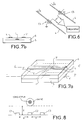
- FIG. 6 represents an ammeter making it possible to carry out a differential measurement of current in two conductors 4 and 4 ′, in which currents of intensities le and ls circulate, with the sensors C4 and C5.
- the intensities of the currents le and ls are measured separately, each using two sensors described above.
- the sensor output signals are then possibly amplified before being compared.
- the applications of this invention relate in particular to differential circuit breakers. Measuring the difference in intensity between the finish line (le) and the output outlet (ls) makes it possible to detect leaks and therefore cut off the flow of current.
- the invention is equally applicable to direct current installations (electronics, navigation) and / or alternating current installations.
- Figure 7a is a way of making a differential ammeter and is derived from the embodiment of Figure 2. It has on each side of the sensor, a conductor 4 and 4 '.
- the conductor 4 is located on the insulating layer 6 and the conductor 4 'is located on the face of the substrate 5 opposite to that carrying the sensitive element 1.
- the insulating layer 3 and the substrate 5 have the same thickness so that the conductors 4, 4 'are at the same distance from the element 1. Provision is made for the currents flowing in the conductors 4 and 4' to be in opposite directions and to be in phase. If these conditions are met, and the currents are equal, the magnetic fields induced by these currents cancel each other out in element 1. On the other hand, if they are not equal, the magnetic field of the strongest current predominates and a non-zero voltage is detected at terminals 3-3 '.
- a differential ammeter can also be produced by providing the conductors 4 and 4 'on the same face of the sensor, for example on the insulating layer 6. The conductors 4 and 4' are then positioned so as to be at the same distance from the sensitive element 1 of the sensor.
Landscapes
- Physics & Mathematics (AREA)
- General Physics & Mathematics (AREA)
- Measuring Instrument Details And Bridges, And Automatic Balancing Devices (AREA)
- Hall/Mr Elements (AREA)
- Measuring Magnetic Variables (AREA)
Applications Claiming Priority (2)
| Application Number | Priority Date | Filing Date | Title |
|---|---|---|---|
| FR9505659A FR2734058B1 (fr) | 1995-05-12 | 1995-05-12 | Amperemetre |
| FR9505659 | 1995-05-12 |
Publications (1)
| Publication Number | Publication Date |
|---|---|
| EP0742441A1 true EP0742441A1 (de) | 1996-11-13 |
Family
ID=9478926
Family Applications (1)
| Application Number | Title | Priority Date | Filing Date |
|---|---|---|---|
| EP96400906A Withdrawn EP0742441A1 (de) | 1995-05-12 | 1996-04-26 | Strommesser |
Country Status (4)
| Country | Link |
|---|---|
| US (1) | US5686879A (de) |
| EP (1) | EP0742441A1 (de) |
| JP (1) | JPH08304466A (de) |
| FR (1) | FR2734058B1 (de) |
Cited By (1)
| Publication number | Priority date | Publication date | Assignee | Title |
|---|---|---|---|---|
| WO2010082115A1 (en) | 2009-01-13 | 2010-07-22 | Seneca S.R.L. | Method for measuring an electrical current |
Families Citing this family (22)
| Publication number | Priority date | Publication date | Assignee | Title |
|---|---|---|---|---|
| EP0874244B1 (de) * | 1997-04-19 | 2002-01-30 | LUST ANTRIEBSTECHNIK GmbH | Verfahren zum Messen von elektrischen Strömen in n Leitern sowie Vorrichtung zur Durchführung des Verfahrens |
| FR2771511B1 (fr) | 1997-11-25 | 2000-02-04 | Thomson Csf | Capteur de champ magnetique et procede de fabrication de ce capteur |
| US6473220B1 (en) | 1998-01-22 | 2002-10-29 | Trivium Technologies, Inc. | Film having transmissive and reflective properties |
| JP2001059851A (ja) * | 1999-08-20 | 2001-03-06 | Yazaki Corp | 電流検出装置及び電流検出方法 |
| FR2809185B1 (fr) | 2000-05-19 | 2002-08-30 | Thomson Csf | Capteur de champ magnetique utilisant la magneto resistance, et procede de fabrication |
| FR2817077B1 (fr) | 2000-11-17 | 2003-03-07 | Thomson Csf | Capacite variable commandable en tension par utilisation du phenomene de "blocage de coulomb" |
| DE10105186A1 (de) * | 2001-02-06 | 2002-08-29 | Bosch Gmbh Robert | Halbleiteranordnung, Strommesser und Kraftfahrzeug |
| FR2828001B1 (fr) * | 2001-07-27 | 2003-10-10 | Thales Sa | Dispositif de commande de renversement de sens d'aimantation sans champ magnetique externe |
| US7595934B2 (en) | 2002-03-26 | 2009-09-29 | Brilliant Film Llc | Integrated sub-assembly having a light collimating or transflecting device |
| US7259545B2 (en) * | 2003-02-11 | 2007-08-21 | Allegro Microsystems, Inc. | Integrated sensor |
| TW200506446A (en) * | 2003-05-20 | 2005-02-16 | Trivium Technologies Inc | Devices for use in non-emissive displays |
| EP1697585A4 (de) * | 2003-12-15 | 2009-04-08 | Univ Yale | Magnetoelektronische vorrichtungen auf basis von dünnschichtfilmen mit cmr (grossem magnetowiderstand) |
| FR2880131B1 (fr) * | 2004-12-23 | 2007-03-16 | Thales Sa | Procede de mesure d'un champ magnetique faible et capteur de champ magnetique a sensibilite amelioree |
| US7768083B2 (en) * | 2006-01-20 | 2010-08-03 | Allegro Microsystems, Inc. | Arrangements for an integrated sensor |
| FR2911690B1 (fr) | 2007-01-19 | 2009-03-06 | Thales Sa | Dispositif d'amplification magnetique comportant un capteur magnetique a sensibilite longitudinale |
| TW200946775A (en) | 2008-02-27 | 2009-11-16 | Brilliant Film Llc | Concentrators for solar power generating systems |
| AT506682B1 (de) * | 2008-04-17 | 2014-05-15 | Adaptive Regelsysteme Ges M B H | Strommesseinrichtung und verfahren zur galvanisch getrennten messung von strömen |
| US7816905B2 (en) * | 2008-06-02 | 2010-10-19 | Allegro Microsystems, Inc. | Arrangements for a current sensing circuit and integrated current sensor |
| US9976876B2 (en) | 2015-11-24 | 2018-05-22 | Allegro Microsystems, Llc | Methods and apparatus for phase selection in ring magnet sensing |
| US10935612B2 (en) | 2018-08-20 | 2021-03-02 | Allegro Microsystems, Llc | Current sensor having multiple sensitivity ranges |
| US11567108B2 (en) | 2021-03-31 | 2023-01-31 | Allegro Microsystems, Llc | Multi-gain channels for multi-range sensor |
| US11994541B2 (en) | 2022-04-15 | 2024-05-28 | Allegro Microsystems, Llc | Current sensor assemblies for low currents |
Citations (2)
| Publication number | Priority date | Publication date | Assignee | Title |
|---|---|---|---|---|
| US3693085A (en) * | 1971-07-15 | 1972-09-19 | Gen Motors Corp | System for calibrated high level current measurement using a magnetic field responsive transistor |
| US5172052A (en) * | 1990-07-23 | 1992-12-15 | Iimorrow, Inc. | Current sensor assembly and method |
Family Cites Families (5)
| Publication number | Priority date | Publication date | Assignee | Title |
|---|---|---|---|---|
| FR2666175B1 (fr) * | 1990-08-21 | 1992-10-16 | Thomson Csf | Transistor a effet de champ a supraconducteur. |
| FR2674067B1 (fr) * | 1991-03-15 | 1993-05-28 | Thomson Csf | Dispositif semiconducteur a effet josephson. |
| FR2675951B1 (fr) * | 1991-04-23 | 1997-08-29 | Thomson Csf | Structure de jonction josephson. |
| FR2685489B1 (fr) * | 1991-12-23 | 1994-08-05 | Thomson Csf | Capteur de champ magnetique faible a effet magnetoresistif. |
| FR2702919B1 (fr) * | 1993-03-19 | 1995-05-12 | Thomson Csf | Transducteur magnétorésistif et procédé de réalisation. |
-
1995
- 1995-05-12 FR FR9505659A patent/FR2734058B1/fr not_active Expired - Fee Related
-
1996
- 1996-04-26 EP EP96400906A patent/EP0742441A1/de not_active Withdrawn
- 1996-04-30 US US08/641,033 patent/US5686879A/en not_active Expired - Fee Related
- 1996-05-10 JP JP8116706A patent/JPH08304466A/ja active Pending
Patent Citations (2)
| Publication number | Priority date | Publication date | Assignee | Title |
|---|---|---|---|---|
| US3693085A (en) * | 1971-07-15 | 1972-09-19 | Gen Motors Corp | System for calibrated high level current measurement using a magnetic field responsive transistor |
| US5172052A (en) * | 1990-07-23 | 1992-12-15 | Iimorrow, Inc. | Current sensor assembly and method |
Cited By (1)
| Publication number | Priority date | Publication date | Assignee | Title |
|---|---|---|---|---|
| WO2010082115A1 (en) | 2009-01-13 | 2010-07-22 | Seneca S.R.L. | Method for measuring an electrical current |
Also Published As
| Publication number | Publication date |
|---|---|
| JPH08304466A (ja) | 1996-11-22 |
| FR2734058B1 (fr) | 1997-06-20 |
| US5686879A (en) | 1997-11-11 |
| FR2734058A1 (fr) | 1996-11-15 |
Similar Documents
| Publication | Publication Date | Title |
|---|---|---|
| FR2734058A1 (fr) | Amperemetre | |
| FR2752302A1 (fr) | Capteur de champ magnetique a pont de magnetoresistances | |
| EP0692098B1 (de) | Vorrichtung zur messung von elektrischem strom mit einem auf magnetfluss ansprechenden wandler, insbesondere für die verwendung bei elektrisch betriebenen fahrzeugen | |
| FR2659177A1 (fr) | Capteur de courant pour un declencheur electronique d'un disjoncteur electrique. | |
| WO1998001764A1 (fr) | Capteur de champ magnetique en couche mince | |
| EP0746747A1 (de) | Verfahren und vorrichtung zum messen, während übergangszustände, der temperatur und des wärmeflusses durch oberflächen | |
| EP1046021B1 (de) | Linearer winkelpositionssensor mit magnetfeldabhängigen widerständen | |
| EP0849799A1 (de) | Bispektraler photoleitender Detektor | |
| FR2842913A1 (fr) | Dispositif compact de mesure de vitesse et de sens de rotation d'un objet | |
| FR2827962A1 (fr) | Dispositif de mesure a effet hall de l'intensite d'un courant electrique | |
| FR2746925A1 (fr) | Dispositif de capteur pour une mesure d'intensite et de tension | |
| FR2904425A1 (fr) | Capteur de courant ameliore a excitation magnetique alternative | |
| FR2787197A1 (fr) | Capteur de champ magnetique a magnetoresistance geante | |
| FR2826723A1 (fr) | Systeme de mesure capacitif | |
| CA2227032A1 (fr) | Capteur de position sans contact, a effet hall | |
| EP2834658B1 (de) | Verfahren und vorrichtung zum messen eines magnetfeldes und der temperatur eines magnetoresistiven wandlers | |
| WO2005066642A1 (fr) | Capteur de courant a sensibilite reduite aux champs magnetiques parasites | |
| WO2017178378A1 (fr) | Appareil de mesure de courants électriques | |
| FR3006056A1 (fr) | Procede de mesure de forts courants electriques par effet magnetique et dispositif de mesure correspondant | |
| EP2157402B1 (de) | Vorrichtung zur Messung der Ausrichtung von zusammengefügten Strukturen | |
| WO2022090499A1 (fr) | Dispositif de détection du couplage capacitif entre un objet et une surface de détection | |
| EP3977148B1 (de) | Magnetfeldsensor | |
| FR2504272A1 (fr) | Transducteur de puissance | |
| FR2782159A1 (fr) | Dispositif de detection d'atteinte a l'integrite d'une paroi | |
| EP0703460B1 (de) | Magnetoresistiver Strommesser |
Legal Events
| Date | Code | Title | Description |
|---|---|---|---|
| PUAI | Public reference made under article 153(3) epc to a published international application that has entered the european phase |
Free format text: ORIGINAL CODE: 0009012 |
|
| AK | Designated contracting states |
Kind code of ref document: A1 Designated state(s): DE GB |
|
| 17P | Request for examination filed |
Effective date: 19970321 |
|
| RAP1 | Party data changed (applicant data changed or rights of an application transferred) |
Owner name: THALES |
|
| 17Q | First examination report despatched |
Effective date: 20030410 |
|
| STAA | Information on the status of an ep patent application or granted ep patent |
Free format text: STATUS: THE APPLICATION IS DEEMED TO BE WITHDRAWN |
|
| 18D | Application deemed to be withdrawn |
Effective date: 20060509 |