EP0742445A2 - Verfahren und Vorrichtung zum Messen der Änderung der Kapazitäten von Doppelkondensatoren - Google Patents
Verfahren und Vorrichtung zum Messen der Änderung der Kapazitäten von Doppelkondensatoren Download PDFInfo
- Publication number
- EP0742445A2 EP0742445A2 EP96302883A EP96302883A EP0742445A2 EP 0742445 A2 EP0742445 A2 EP 0742445A2 EP 96302883 A EP96302883 A EP 96302883A EP 96302883 A EP96302883 A EP 96302883A EP 0742445 A2 EP0742445 A2 EP 0742445A2
- Authority
- EP
- European Patent Office
- Prior art keywords
- capacitors
- circuit
- capacitor
- calculating
- frequency
- Prior art date
- Legal status (The legal status is an assumption and is not a legal conclusion. Google has not performed a legal analysis and makes no representation as to the accuracy of the status listed.)
- Withdrawn
Links
Images
Classifications
-
- G—PHYSICS
- G01—MEASURING; TESTING
- G01R—MEASURING ELECTRIC VARIABLES; MEASURING MAGNETIC VARIABLES
- G01R27/00—Arrangements for measuring resistance, reactance, impedance, or electric characteristics derived therefrom
- G01R27/02—Measuring real or complex resistance, reactance, impedance, or other two-pole characteristics derived therefrom, e.g. time constant
- G01R27/26—Measuring inductance or capacitance; Measuring quality factor, e.g. by using the resonance method; Measuring loss factor; Measuring dielectric constants ; Measuring impedance or related variables
- G01R27/2605—Measuring capacitance
-
- G—PHYSICS
- G01—MEASURING; TESTING
- G01D—MEASURING NOT SPECIALLY ADAPTED FOR A SPECIFIC VARIABLE; ARRANGEMENTS FOR MEASURING TWO OR MORE VARIABLES NOT COVERED IN A SINGLE OTHER SUBCLASS; TARIFF METERING APPARATUS; MEASURING OR TESTING NOT OTHERWISE PROVIDED FOR
- G01D5/00—Mechanical means for transferring the output of a sensing member; Means for converting the output of a sensing member to another variable where the form or nature of the sensing member does not constrain the means for converting; Transducers not specially adapted for a specific variable
- G01D5/12—Mechanical means for transferring the output of a sensing member; Means for converting the output of a sensing member to another variable where the form or nature of the sensing member does not constrain the means for converting; Transducers not specially adapted for a specific variable using electric or magnetic means
- G01D5/14—Mechanical means for transferring the output of a sensing member; Means for converting the output of a sensing member to another variable where the form or nature of the sensing member does not constrain the means for converting; Transducers not specially adapted for a specific variable using electric or magnetic means influencing the magnitude of a current or voltage
- G01D5/24—Mechanical means for transferring the output of a sensing member; Means for converting the output of a sensing member to another variable where the form or nature of the sensing member does not constrain the means for converting; Transducers not specially adapted for a specific variable using electric or magnetic means influencing the magnitude of a current or voltage by varying capacitance
- G01D5/2405—Mechanical means for transferring the output of a sensing member; Means for converting the output of a sensing member to another variable where the form or nature of the sensing member does not constrain the means for converting; Transducers not specially adapted for a specific variable using electric or magnetic means influencing the magnitude of a current or voltage by varying capacitance by varying dielectric
-
- G—PHYSICS
- G01—MEASURING; TESTING
- G01P—MEASURING LINEAR OR ANGULAR SPEED, ACCELERATION, DECELERATION, OR SHOCK; INDICATING PRESENCE, ABSENCE, OR DIRECTION, OF MOVEMENT
- G01P15/00—Measuring acceleration; Measuring deceleration; Measuring shock, i.e. sudden change of acceleration
- G01P15/02—Measuring acceleration; Measuring deceleration; Measuring shock, i.e. sudden change of acceleration by making use of inertia forces using solid seismic masses
- G01P15/08—Measuring acceleration; Measuring deceleration; Measuring shock, i.e. sudden change of acceleration by making use of inertia forces using solid seismic masses with conversion into electric or magnetic values
- G01P15/125—Measuring acceleration; Measuring deceleration; Measuring shock, i.e. sudden change of acceleration by making use of inertia forces using solid seismic masses with conversion into electric or magnetic values by capacitive pick-up
-
- G—PHYSICS
- G01—MEASURING; TESTING
- G01R—MEASURING ELECTRIC VARIABLES; MEASURING MAGNETIC VARIABLES
- G01R19/00—Arrangements for measuring currents or voltages or for indicating presence or sign thereof
- G01R19/10—Measuring sum, difference or ratio
Definitions
- This invention relates to circuits for measuring the change in capacitance values of two capacitors and more particularly to circuits for measuring the change in capacitance values in dual capacitors.
- dual capacitors are comprised of two individual capacitors sharing a common electrode.
- the two capacitors can both be fixed, one can be fixed and one can be variable, or both can be variable; the dual variable form being the most common.
- dual inversely variable capacitors are the most common form of dual capacitors used in measurement applications. Dual inversely variable capacitors are comprised of two individual capacitors sharing a common electrode that are arranged such that the movement of an object in contact with, or proximate to, the two capacitors will increase the capacitance in one capacitor and decrease the capacitance in the other capacitor.
- the differential capacitor has a movable rotor interposed between a fixed common electrode and a first fixed independent electrode and second fixed independent electrode; the common electrode and first independent electrode forming a first capacitor and the common electrode and the second independent electrode forming a second capacitor.
- the rotation of the rotor increases the area of the first independent electrode adjacent to the common electrode and decreases (by the same amount) the area of the second independent electrode adjacent to the common electrode.
- the capacitance of the first capacitor increases by a certain amount while the capacitance of the second capacitor decreases by the certain amount.
- the dual inversely variable capacitors are comprised of a movable common electrode interposed between a first fixed independent electrode and a second fixed independent electrode; the common electrode and first independent electrode forming a first capacitor and the common electrode and the second independent electrode forming a second capacitor.
- the capacitance of the first capacitor decreases while the capacitance of the second capacitor increases.
- the amount of the decrease in capacitance of the first capacitor is not equal to the amount of the increase in capacitance of the second capacitor.
- Dual inversely variable capacitors are often used to measure the movement of a body relative to a fixed point or to another body because dual inversely variable capacitors do not contain any electrical contacts that can become fouled.
- the dual inversely variable capacitors are connected to a measuring circuit that uses the change in capacitances to calculate the movement of the body.
- capacitance bridge circuits and circuits containing subtractors and integrators are used as measuring circuits.
- the measuring circuit is comprised of an AC source having a voltage V s , a bridge circuit comprised of a fixed resistor R1 connected in series with a variable resistor R2 and series connected capacitors C 1 and C 2 connected in parallel to R1 and R2, a full wave rectifier and a DC amplifier.
- the first embodiment of the measuring circuit is comprised of a square-wave generator, an integrator, parallel connected capacitors C 1 and C 2 , two current amplifiers and an A/D converter.
- the square-wave generator generates a train of square-wave voltage pulses of period length T.
- the square-wave voltage pulses are converted in the integrator into a train of triangular-wave voltage pulses having a peak-to-peak value U ss and a period length T.
- the triangular-wave voltage pulses are supplied to the connected electrodes of C 1 and C 2 .
- the A/D converter means determines two digital amplitude values of U 1 (t) at an interval of half a signal period (T/2), said digital amplitude values being designated U s1 and U s2 .
- the A/D converter determines two digital amplitude values of U 2 (t) at an interval of half a signal period (T/2), said digital amplitude values being designated U s3 and U s4 .
- Van Seeters discloses a second embodiment of the 528 Patent measuring circuit wherein two A/D converters are used instead of the one A/D converter.
- One A/D converter is placed in one leg of the measuring circuit after one of the current amplifiers and the other A/D converter is placed in the other leg of the measuring circuit after the other current amplifier.
- the two A/D converters enable the measuring circuit to determine U s1 and U s2 parallel in time with U s3 and U s4 , i.e., the two sets of digital amplitude values are determined in one signal period rather than in two signal periods.
- the 429 Patent measuring circuit is susceptible to mutual drifts in the capacitors caused by temperature and other environmental factors because the measuring circuit assumes that the sum of the capacitances, (C 1 + C 2 ), is a constant.
- the 429 Patent measuring circuit is susceptible to drifts in the voltage, V s , of the AC source because the output, e , is a function of V s as shown earlier.
- the 528 Patent measuring circuit is not susceptible to mutual drifts in the capacitors because the measured characteristic is equal to the ratio of the capacitances, C 1 /C 2 , which cancels out any drift.
- the first embodiment of the 528 Patent measuring circuit requires a square-wave generator. Square-wave voltage pulses are necessary because upon integration, they must yield triangular-wave voltage pulses that can be differentiated and have defined slopes. In addition, the square-wave generator must be stable. The triangular-wave voltage pulses and, thus, the square-wave voltage pulses must be reproducible over two successive signal periods, i.e., they must have the same amplitude and their mutually corresponding half-wave portions must have the same duration. Thus, for practical purposes, the square-wave voltage pulses generated by the square-wave generator 40 must have identical amplitudes and half-wave durations.
- the second embodiment of the 528 Patent measuring circuit does not require the triangular-wave voltage pulses and, thus, the square-wave voltage pulses to have identical amplitudes or half-wave durations since U s1 , U s2 and U s3 , U s4 are determined during the same signal period.
- the second embodiment of the 528 Patent measuring circuit still requires a square-wave generator.
- both embodiments of the 528 Patent measuring circuit require a square-wave generator.
- the invention is embodied as a circuit is connected to first and second capacitors which have first and second capacitance values C 1 and C 2 .
- the first and second capacitors each have an independent electrode and share one common electrode.
- the circuit calculates a ratio, R, having C 1 in inverse relation to C 2 .
- the circuit includes a means which generates and supplies an AC voltage to the common electrode to thereby produce first and second AC current signals at the independent electrodes of the capacitors.
- the circuit further includes a rectifying means connected to the independent electrodes for respectively converting the first and second AC current signals to first and second half-wave current signals.
- the circuit also includes a means connected to the rectifying means for respectively converting the first and second half-wave current signals to first and second frequency signals respectively having frequency values f 1 and f 2 ; and a means for calculating R from f 1 and f 2 .
- the invention is also embodied as an apparatus for measuring a displacement, D, of a first object relative to a second object where D is in a range having a maximum D max and a minimum D min .
- the apparatus includes first and second capacitors which have capacitance values C 1 and C 2 and are connected to the first and second objects.
- the first and second capacitors each have an independent electrode and share one common electrode.
- the first and second capacitors are arranged such that the displacement of the first object causes a proportional change in C 1 .
- the apparatus also includes a means for generating an AC voltage V s and supplying V s to the common electrode to thereby produce first and second AC current signals at the independent electrodes of the capacitors.
- the apparatus further includes a rectifying means connected to the independent electrodes for respectively converting the first and second AC current signals to first and second half-wave current signals and a means connected to the rectifying means for converting the first and second half-wave current signals to first and second frequency signals respectively having frequency values f 1 and f 2 .
- the apparatus also further includes means for calculating from f 1 and f 2 a ratio, R, having C 1 in inverse relation to C 2 .
- R a ratio
- There is also included a means for storing the value of R, R min , when the displacement of the first body is at D min and for storing the value of R, R max , when the displacement of the first body is at D max ; and a means for calculating D in accordance with D ( R - R min ) ⁇ D max - D min R max - R min .
- the invention is also embodied as a method for calculating a ratio, R, having a capacitance value, C 1 , in inverse relation to a capacitance value, C 2 , where C 1 and C 2 are the capacitance values of a first and second capacitor respectively.
- the first and second capacitors each have an independent electrode and share one common electrode.
- the method includes the steps generating and supplying an AC voltage to the common electrode to thereby produce first and second AC current signals at the independent electrodes of the capacitors.
- the method includes the steps of converting the first AC current signal to a first half-wave current signal; converting the second AC current signal to a second half-wave current signal; converting the first half-wave current signal to a first frequency signal having a frequency value f 1 ; and converting the second half-wave current signal to a second frequency signal having a frequency value f 2 .
- the method further includes the step of calculating R from f 1 and f 2 .
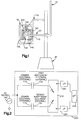
- Fig.1 shows a representative drawing of a displacement measuring apparatus containing a measuring circuit embodied in accordance with the present invention.
- Fig.2 shows a representative drawing of the measuring circuit embodied in accordance with the present invention.
- Fig.3 shows an elementary schematic of an analog switching means used in the measuring circuit embodied in accordance with the present invention.
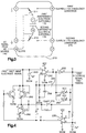
- Fig.4 shows an elementary schematic of a current-to-frequency converter used in the measuring circuit embodied in accordance with the present invention.
- Fig.1 there is shown a representative drawing of a displacement measuring apparatus 5 containing a measuring circuit 200 embodied in accordance with the present invention.
- the displacement measuring apparatus 5 is comprised of a housing 40, a bracket 12, an armature 15, a rod 20, a base 30, the measuring circuit 200, an AC source 140 and a differential capacitor 100 having a half-plate rotor 120.
- the differential capacitor 100 is secured within the housing 40.
- the rod 20 is connected to the center of the half-plate rotor 120 and passes through an opening in the differential capacitor 100 and an opening in the housing 40.
- the bracket 12 is connected to the base 30 and the housing 40, thereby securing the differential capacitor 100 in a position which permits the rod 20 to pass through an opening in the base 30 and connect with the armature 15.
- the rod 20 acts as an axle about which the half-plate rotor 120 rotates when a torque perpendicular to Fig.1 is applied to the armature 15.
- the differential capacitor 100 is comprised of the half-plate rotor 120, a common electrode 110, a first independent electrode 132 and a second independent electrode 134.
- the common electrode 110 is mounted parallel to the first and second independent electrodes 132 and 134.
- the common electrode 110 and first independent electrode 132 form a first capacitor and the common electrode 110 and the second independent electrode 134 form a second capacitor.
- the half-plate rotor 120 is rotatably mounted between the common electrode 110 and first and second independent electrodes 132 and 134.
- the AC source 140 is electrically connected to the common electrode 110 and the half-plate rotor 120 is connected to circuit common.
- the first independent electrode 132 and second independent electrode 134 are connected to the capacitance measuring circuit 200.
- I V R 2 + X L - X C 2
- I the effective current
- V the effective voltage
- R the resistance
- X L inductive reactance
- X C the capacitive reactance of the circuit
- the measuring circuit 200 is comprised of an analog switching means 210, a first current-to-frequency converter 220, a second current-to-frequency converter 225 and a microcontroller 250.
- the analog switching means 210 used in the current invention is a quadruple pole, double-throw switch. More specifically, the analog switching means 210 is a monolithic, charge-balanced, dual switched-capacitor instrumentation integrated circuit manufactured by Linear Technology Corporation and commercially available as part number LTC1043. An elementary schematic of the analog switching means 210 is shown in Fig. 3.
- the AC signal from the AC source 140 is brought into Pin 16 of the analog switching means 210 and is used as an external clock, overriding the internal oscillator (not shown) of the analog switching means 210.
- the first independent electrode 132 and the second independent electrode 134 are respectively connected to one side of internal switches 211 and 212 at Pins 11 and 12.
- the other side of internal switches 211 and 212 are respectively connected through Pins 8 and 14 to the first current-to-frequency converter 220 and the second current-to-frequency converter 225.
- the opening and closing of the internal switches 211 and 212 is controlled by the frequency of the AC signal such that the internal switches 211 and 212 act as half-wave rectifiers.
- the AC current signals from the first independent electrode 132 and second independent electrode 134 respectively exit the analog switching means 210 from Pins 8 and 14 as first and second half-wave electrode signals.
- the current, I 1 , of the first half-wave electrode signal varies between 3 and 6 ⁇ A avg in proportion to changes in C 1 .
- the current, I 2 , of the second half-wave electrode signal varies between 3 and 6 ⁇ A avg in proportion to changes in C 2 .
- the first and second current-to-frequency converters (220, 225) respectively convert the first and second half-wave electrode signals to first and second electrode signals having varying frequencies.
- the first and second current-to-frequency converters (220, 225) of the present invention are ideally suited for converting small current signals such as I 1 and I 2 to frequency signals. With small currents, the first and second current-to-frequency converters (220, 225) retain their linearity and provide essentially infinite resolution.
- Fig.4 there is shown an elementary schematic of the first current-to-frequency converter 220.
- the first half-wave electrode signal is connected to a .1 ⁇ F capacitor 245 and the positive input of comparator 240.
- the .1 ⁇ F capacitor 245 filters the first half-wave electrode signal, creating a continuous positive going voltage ramp at the positive input to comparator 240. Assuming the positive input of comparator 240 to be below the negative input to comparator 240 (the output of comparator 230 is low), the output of comparator 240 will be low while the voltage at the positive input to comparator 240 is ramping.
- the inverters (250, 260) When the output of comparator 240 is low, the inverters (250, 260) will be switched high, permitting current to flow from the reference VCC through the supply pins of the inverters (250, 260) to a 1500 pF capacitor 270.
- the voltage to which the 1500 pF capacitor 270 charges is a function of the potential of VCC and the drop across transistor 280.
- the feedback drops the negative input of comparator 240, thereby delaying the output of comparator 240 from going low and permitting a complete discharge of the 1500 pF capacitor 270.
- the Schottky diode 298 prevents the negative input to comparator 240 to be driven outside its negative common-mode limit.
- comparator 240 switches low and the entire cycle repeats. The period of the cycle depends directly on the current of the first half-wave electrode signal.
- the frequency, f 1 of the first electrode signal output by the first current-to-frequency converter 220 varies proportionally with changes in the current I 1 of the first half-wave electrode signal.
- the second current-to-frequency converter 225 is identical in structure and function to the first current-to-frequency converter 220. Accordingly, a schematic of the second current-to-frequency converter 225 is not included.
- the second current-to-frequency converter 225 operates to generate the second electrode signal which has a frequency, f 2 , that varies proportionally with changes in the current I 2 of the second half-wave electrode signal.
- the first and second electrode signals from the first and second current-to-frequency converters (220, 225) are ideally suited for input into the microcontroller 250 since they are frequency signals with a range of 800 to 1600 Hz.
- the microcontroller 250 is a Motorola MC68H 8-bit microcontroller having a 16-bit free running counter (not shown) that is clocked by the output of a four-stage prescaler (not shown) driven by an MCU E clock (not shown).
- the first and second electrode signals are received by first and second input channels (not shown) in the microcontroller 250.
- the first and second input channels are respectively monitored by first and second input capture edge detectors (not shown).
- the first and second input capture edge detectors respectively sense falling edges in the first and second electrode signals.
- a beginning value of the counter is held in a first input capture register.
- an ending value of the counter is held in the first input capture register. The beginning counter value is subtracted from the ending counter value and the difference is divided by the number of falling edges detected during the sample period to yield the frequency value, f 1.
- a beginning value of the counter is held in a second input capture register.
- an ending value of the counter is held in the second input capture register. The beginning counter value is subtracted from the ending counter value and the difference is divided by the number of falling edges detected during the sample period to yield the frequency value, f 2, It should be appreciated that the same values for f 1 and f 2 would be obtained by having the input capture edge detectors encoded to sense rising edges in the first and second electrode signals instead of falling edges.
- a program in the read only memory (ROM) portion (not shown) of the microprocessor 250 accesses the first and second input capture registers, thereby obtaining the frequency values, f 1 and f 2 , of the first and second electrode signals.
- R is equal to R f because C 1 and C 2 are directly proportional to f 1 and f 2 respectively and the constant parameters for f 1 and f 2 cancel out in the ratio.
- the ROM program uses R to calculate the angular displacement, A, of the half-plate rotor 120 and, thus, the armature 15. It should be appreciated that other ratios could be used wherein f 1 and f 2 are in inverse relation to each other, i.e., ratios where f 1 is in the numerator and f 2 is in the denominator or f 2 is in the numerator and f 1 is in the denominator.
- the armature 15 (shown in Fig.1) is moved to its two extreme positions, i.e., 0° displacement and 90° displacement.
- the ROM program calculates R at 0° and 90° displacement, respectively yielding calibration frequency ratio values R 0 and R 90 .
- the values R 0 and R 90 are stored in the electrically erasable programmable read-only memory (EEPROM) portion (not shown) of the microcontroller 250 for use during the normal operation of the measuring circuit 200.
- EEPROM electrically erasable programmable read-only memory
- the measuring circuit 200 calculates A using R, which is a ratio, the constant parameters for f 1 and f 2 cancel out and, thus, do not appear in the linear relationship used to calculate A. In addition, any mutual drifts occurring in the first and second capacitors arising from the environment and any drifts in the frequency or amplitude of the AC source 140 are canceled out. Thus, the measuring circuit 200 measures the change in capacitance values C 1 and C 2 in the differential capacitor 100 without being susceptible to mutual drifts in the first and second capacitors or drifts in the AC source 140. The measuring circuit 200 accomplishes the foregoing while consuming less than 5 milliwatts of power. Such low power consumption eases intrinsic safety concerns.
- the measuring circuit of the present invention is equally well suited for use with dual capacitors wherein one capacitor is fixed and one capacitor is variable.
- the change in capacitance (and corresponding frequency value) of the variable capacitor will provide the necessary measure of displacement while any fluctuation in the capacitance (and corresponding frequency value) of the fixed capacitor caused by mutual drifts in the capacitors or drifts in the AC source will provide the necessary cancellation of the corresponding fluctuation in the capacitance (and corresponding frequency value) of the variable capacitor.
Landscapes
- Physics & Mathematics (AREA)
- General Physics & Mathematics (AREA)
- Measurement Of Resistance Or Impedance (AREA)
- Transmission And Conversion Of Sensor Element Output (AREA)
Applications Claiming Priority (2)
| Application Number | Priority Date | Filing Date | Title |
|---|---|---|---|
| US08/439,305 US5594353A (en) | 1995-05-11 | 1995-05-11 | Method and apparatus for measuring the change in capacitance values in dual capacitors |
| US439305 | 1995-05-11 |
Publications (2)
| Publication Number | Publication Date |
|---|---|
| EP0742445A2 true EP0742445A2 (de) | 1996-11-13 |
| EP0742445A3 EP0742445A3 (de) | 1997-08-06 |
Family
ID=23744158
Family Applications (1)
| Application Number | Title | Priority Date | Filing Date |
|---|---|---|---|
| EP96302883A Withdrawn EP0742445A3 (de) | 1995-05-11 | 1996-04-25 | Verfahren und Vorrichtung zum Messen der Änderung der Kapazitäten von Doppelkondensatoren |
Country Status (9)
| Country | Link |
|---|---|
| US (1) | US5594353A (de) |
| EP (1) | EP0742445A3 (de) |
| JP (1) | JPH08304488A (de) |
| KR (1) | KR960042073A (de) |
| CN (1) | CN1140260A (de) |
| AU (1) | AU676125B2 (de) |
| BR (1) | BR9602205A (de) |
| CA (1) | CA2174900C (de) |
| NO (1) | NO961858L (de) |
Cited By (2)
| Publication number | Priority date | Publication date | Assignee | Title |
|---|---|---|---|---|
| RU2173859C1 (ru) * | 2000-11-10 | 2001-09-20 | Ульяновский государственный технический университет | Устройство для измерения емкости конденсатора |
| RU2216027C2 (ru) * | 1998-07-23 | 2003-11-10 | Инфинеон Текнолоджиз Аг | Способ определения очень малых емкостей и его применение |
Families Citing this family (19)
| Publication number | Priority date | Publication date | Assignee | Title |
|---|---|---|---|---|
| US5999010A (en) * | 1997-12-08 | 1999-12-07 | Simplex Solutions, Inc. | Method of measuring interconnect coupling capacitance in an IC chip |
| US6366099B1 (en) * | 1999-12-21 | 2002-04-02 | Conrad Technologies, Inc. | Differential capacitance sampler |
| CH707868B1 (de) * | 2002-08-02 | 2014-10-31 | Oblamatik Ag | Kapazitive Sensorvorrichtung und Installationen mit einer solchen Sensorvorrichtung. |
| US6987394B1 (en) * | 2003-09-22 | 2006-01-17 | Sun Microsystems, Inc. | Full-wave rectifier for capacitance measurements |
| US7116091B2 (en) * | 2004-03-04 | 2006-10-03 | Zircon Corporation | Ratiometric stud sensing |
| US7148703B2 (en) * | 2004-05-14 | 2006-12-12 | Zircon Corporation | Auto-deep scan for capacitive sensing |
| JP2006071629A (ja) * | 2004-09-02 | 2006-03-16 | Ad Semicondutor Co Ltd | 静電容量変化検出方法及び検出集積回路 |
| CN100386964C (zh) * | 2005-03-04 | 2008-05-07 | 清华大学 | 开关电容电路中用交流电源供电的放大器 |
| TW201128499A (en) * | 2010-02-04 | 2011-08-16 | Novatek Microelectronics Corp | Touch sensing system, capacitance sensing circuit and capacitance sensing method thereof |
| TWI507949B (zh) * | 2010-02-08 | 2015-11-11 | Novatek Microelectronics Corp | 觸控感測系統、電容感測電路及電容感測方法 |
| CN102156595B (zh) * | 2010-02-12 | 2014-04-30 | 联咏科技股份有限公司 | 触控感测系统、电容感测电路及电容感测方法 |
| DE102012004913B4 (de) * | 2012-03-09 | 2014-04-10 | Paragon Ag | Vorrichtung zur Bestimmung eines zu einem Verhältnis von Induktivitäten bzw. Kapazitäten zweier induktiver bzw. kapazitiver Bauteile proportionalen Messwerts und entsprechendes Verfahren |
| US8829925B2 (en) * | 2012-06-20 | 2014-09-09 | Hamilton Sundstrand Corporation | Capacitive position sensor |
| US8836349B2 (en) * | 2012-08-15 | 2014-09-16 | Robert Bosch Gmbh | Capacitive sensor |
| KR101472001B1 (ko) | 2012-12-06 | 2014-12-15 | 이성호 | Ac 전원에 연동한 커패시턴스 검출 수단 및 방법 |
| CN103630755B (zh) * | 2013-11-27 | 2016-09-14 | 北京天诚同创电气有限公司 | 变流器直流母线支撑电容检测方法 |
| US10921284B2 (en) | 2017-04-19 | 2021-02-16 | Roche Sequencing Solutions, Inc. | Phased nanopore array |
| CN109387701B (zh) * | 2017-08-02 | 2021-03-19 | 台达电子工业股份有限公司 | 三相变流装置及电容估算方法 |
| CN111142058B (zh) * | 2020-01-02 | 2022-05-17 | 联芸科技(杭州)有限公司 | 电阻检测装置及方法 |
Family Cites Families (12)
| Publication number | Priority date | Publication date | Assignee | Title |
|---|---|---|---|---|
| US3775687A (en) * | 1971-12-17 | 1973-11-27 | H Machlanski | Capacitance difference measuring circuit |
| US4093915A (en) * | 1976-01-12 | 1978-06-06 | Setra Systems, Inc. | Capacitance measuring system |
| US4187459A (en) * | 1978-02-13 | 1980-02-05 | Automatic Systems Laboratories Limited | Digital measurement of impedance ratios |
| JPS5562310A (en) * | 1978-10-20 | 1980-05-10 | Hiromi Ogasawara | Direct-acting type displacement detector |
| JPS59120728A (ja) * | 1982-12-27 | 1984-07-12 | Nissan Motor Co Ltd | 燃料噴射ポンプの吐出量調整装置 |
| US4841227A (en) * | 1987-06-01 | 1989-06-20 | Simmonds Precision Products, Inc. | Apparatus for the ratiometric measurement of a quantity of liquid in a tank |
| US4794320A (en) * | 1987-08-10 | 1988-12-27 | Moore Products Co. | Multi-frequency capacitance sensor |
| GB8808614D0 (en) * | 1988-04-12 | 1988-05-11 | Renishaw Plc | Displacement-responsive devices with capacitive transducers |
| GB2223589B (en) * | 1988-09-14 | 1991-07-24 | Valk Rob V D | Measurement of capacitance and parameters related thereto |
| DE4107366C1 (de) * | 1991-03-08 | 1992-04-23 | Leica Heerbrugg Ag, Heerbrugg, Ch | |
| US5323118A (en) * | 1991-11-12 | 1994-06-21 | Copal Company, Limited | Hinged displacement sensor |
| FR2712690B1 (fr) * | 1993-11-17 | 1995-12-15 | Snecma | Dispositif pour effectuer la mesure dynamique de la distance entre les faces en regard du rotor et du stator d'une machine tournante. |
-
1995
- 1995-05-11 US US08/439,305 patent/US5594353A/en not_active Expired - Fee Related
-
1996
- 1996-04-24 CA CA002174900A patent/CA2174900C/en not_active Expired - Fee Related
- 1996-04-25 EP EP96302883A patent/EP0742445A3/de not_active Withdrawn
- 1996-05-07 AU AU52127/96A patent/AU676125B2/en not_active Ceased
- 1996-05-08 NO NO961858A patent/NO961858L/no unknown
- 1996-05-09 BR BR9602205A patent/BR9602205A/pt not_active Application Discontinuation
- 1996-05-10 JP JP8139731A patent/JPH08304488A/ja not_active Withdrawn
- 1996-05-10 CN CN96100299A patent/CN1140260A/zh active Pending
- 1996-05-10 KR KR1019960015323A patent/KR960042073A/ko not_active Withdrawn
Cited By (2)
| Publication number | Priority date | Publication date | Assignee | Title |
|---|---|---|---|---|
| RU2216027C2 (ru) * | 1998-07-23 | 2003-11-10 | Инфинеон Текнолоджиз Аг | Способ определения очень малых емкостей и его применение |
| RU2173859C1 (ru) * | 2000-11-10 | 2001-09-20 | Ульяновский государственный технический университет | Устройство для измерения емкости конденсатора |
Also Published As
| Publication number | Publication date |
|---|---|
| CN1140260A (zh) | 1997-01-15 |
| NO961858L (no) | 1996-11-12 |
| BR9602205A (pt) | 1998-04-07 |
| EP0742445A3 (de) | 1997-08-06 |
| CA2174900A1 (en) | 1996-11-12 |
| US5594353A (en) | 1997-01-14 |
| AU676125B2 (en) | 1997-02-27 |
| KR960042073A (ko) | 1996-12-19 |
| JPH08304488A (ja) | 1996-11-22 |
| AU5212796A (en) | 1996-11-21 |
| CA2174900C (en) | 1999-02-23 |
| NO961858D0 (no) | 1996-05-08 |
Similar Documents
| Publication | Publication Date | Title |
|---|---|---|
| EP0742445A2 (de) | Verfahren und Vorrichtung zum Messen der Änderung der Kapazitäten von Doppelkondensatoren | |
| JP3139305B2 (ja) | 容量型加速度センサ | |
| US7119551B2 (en) | Capacitive sensor | |
| US4644799A (en) | Electromagnetic flow meter | |
| EP0698780B1 (de) | Differentialkapazitivgeber | |
| JPS63241416A (ja) | 測定対象の測定量を測定するための方法及び装置 | |
| JP2005535900A (ja) | 増幅器フィードバック経路に容量性圧力センサを備えた圧力測定装置 | |
| US5189376A (en) | Method for the measurment of capacitance, with application to linear measurement of distance | |
| JPS627961B2 (de) | ||
| JPS62121312A (ja) | 静電容量−電圧変換回路 | |
| JPH07260510A (ja) | 容量型センサ | |
| SU1767451A1 (ru) | Измерительный преобразователь с емкостным датчиком | |
| JPH0739927B2 (ja) | 位置検出装置 | |
| JP2589817Y2 (ja) | Lcrテスタ | |
| SU1370460A1 (ru) | Измерительный преобразователь напр жени индукционных датчиков | |
| SU1711094A1 (ru) | Преобразователь емкости датчика | |
| RU2100813C1 (ru) | Способ измерения rlc-параметров | |
| SU1525619A1 (ru) | Преобразователь параметров емкостных датчиков во временной интервал и напр жение | |
| JP4298062B2 (ja) | 容量計測回路 | |
| JPS6322265B2 (de) | ||
| CN100523835C (zh) | 电容-电压转换电路 | |
| KR960013754B1 (ko) | 직렬 저항 보상 기능을 갖는 적분형 콘덴서 측정 회로 | |
| SU1201686A1 (ru) | Емкостной измеритель уровн | |
| KR950006886Y1 (ko) | 콘덴서 용량 측정회로 | |
| JPH0313741Y2 (de) |
Legal Events
| Date | Code | Title | Description |
|---|---|---|---|
| PUAI | Public reference made under article 153(3) epc to a published international application that has entered the european phase |
Free format text: ORIGINAL CODE: 0009012 |
|
| AK | Designated contracting states |
Kind code of ref document: A2 Designated state(s): DE ES FR GB IT NL |
|
| PUAL | Search report despatched |
Free format text: ORIGINAL CODE: 0009013 |
|
| AK | Designated contracting states |
Kind code of ref document: A3 Designated state(s): DE ES FR GB IT NL |
|
| STAA | Information on the status of an ep patent application or granted ep patent |
Free format text: STATUS: THE APPLICATION HAS BEEN WITHDRAWN |
|
| 18W | Application withdrawn |
Withdrawal date: 19980127 |
|
| 17P | Request for examination filed |
Effective date: 19980113 |