EP0742601A1 - Zylindrische Batterie mit spiralförmig gewickelten Elektrodenblock - Google Patents
Zylindrische Batterie mit spiralförmig gewickelten Elektrodenblock Download PDFInfo
- Publication number
- EP0742601A1 EP0742601A1 EP96302727A EP96302727A EP0742601A1 EP 0742601 A1 EP0742601 A1 EP 0742601A1 EP 96302727 A EP96302727 A EP 96302727A EP 96302727 A EP96302727 A EP 96302727A EP 0742601 A1 EP0742601 A1 EP 0742601A1
- Authority
- EP
- European Patent Office
- Prior art keywords
- electrode
- porosity layer
- cylindrical battery
- electrode group
- battery
- Prior art date
- Legal status (The legal status is an assumption and is not a legal conclusion. Google has not performed a legal analysis and makes no representation as to the accuracy of the status listed.)
- Granted
Links
Images


Classifications
-
- H—ELECTRICITY
- H01—ELECTRIC ELEMENTS
- H01M—PROCESSES OR MEANS, e.g. BATTERIES, FOR THE DIRECT CONVERSION OF CHEMICAL ENERGY INTO ELECTRICAL ENERGY
- H01M4/00—Electrodes
- H01M4/02—Electrodes composed of, or comprising, active material
- H01M4/04—Processes of manufacture in general
- H01M4/0402—Methods of deposition of the material
- H01M4/0419—Methods of deposition of the material involving spraying
-
- H—ELECTRICITY
- H01—ELECTRIC ELEMENTS
- H01M—PROCESSES OR MEANS, e.g. BATTERIES, FOR THE DIRECT CONVERSION OF CHEMICAL ENERGY INTO ELECTRICAL ENERGY
- H01M10/00—Secondary cells; Manufacture thereof
- H01M10/24—Alkaline accumulators
- H01M10/28—Construction or manufacture
- H01M10/286—Cells or batteries with wound or folded electrodes
-
- H—ELECTRICITY
- H01—ELECTRIC ELEMENTS
- H01M—PROCESSES OR MEANS, e.g. BATTERIES, FOR THE DIRECT CONVERSION OF CHEMICAL ENERGY INTO ELECTRICAL ENERGY
- H01M10/00—Secondary cells; Manufacture thereof
- H01M10/34—Gastight accumulators
- H01M10/345—Gastight metal hydride accumulators
-
- H—ELECTRICITY
- H01—ELECTRIC ELEMENTS
- H01M—PROCESSES OR MEANS, e.g. BATTERIES, FOR THE DIRECT CONVERSION OF CHEMICAL ENERGY INTO ELECTRICAL ENERGY
- H01M4/00—Electrodes
- H01M4/02—Electrodes composed of, or comprising, active material
-
- H—ELECTRICITY
- H01—ELECTRIC ELEMENTS
- H01M—PROCESSES OR MEANS, e.g. BATTERIES, FOR THE DIRECT CONVERSION OF CHEMICAL ENERGY INTO ELECTRICAL ENERGY
- H01M4/00—Electrodes
- H01M4/02—Electrodes composed of, or comprising, active material
- H01M4/04—Processes of manufacture in general
-
- H—ELECTRICITY
- H01—ELECTRIC ELEMENTS
- H01M—PROCESSES OR MEANS, e.g. BATTERIES, FOR THE DIRECT CONVERSION OF CHEMICAL ENERGY INTO ELECTRICAL ENERGY
- H01M4/00—Electrodes
- H01M4/02—Electrodes composed of, or comprising, active material
- H01M4/04—Processes of manufacture in general
- H01M4/0402—Methods of deposition of the material
- H01M4/0404—Methods of deposition of the material by coating on electrode collectors
-
- H—ELECTRICITY
- H01—ELECTRIC ELEMENTS
- H01M—PROCESSES OR MEANS, e.g. BATTERIES, FOR THE DIRECT CONVERSION OF CHEMICAL ENERGY INTO ELECTRICAL ENERGY
- H01M4/00—Electrodes
- H01M4/02—Electrodes composed of, or comprising, active material
- H01M4/04—Processes of manufacture in general
- H01M4/043—Processes of manufacture in general involving compressing or compaction
-
- H—ELECTRICITY
- H01—ELECTRIC ELEMENTS
- H01M—PROCESSES OR MEANS, e.g. BATTERIES, FOR THE DIRECT CONVERSION OF CHEMICAL ENERGY INTO ELECTRICAL ENERGY
- H01M4/00—Electrodes
- H01M4/02—Electrodes composed of, or comprising, active material
- H01M4/24—Electrodes for alkaline accumulators
- H01M4/242—Hydrogen storage electrodes
-
- H—ELECTRICITY
- H01—ELECTRIC ELEMENTS
- H01M—PROCESSES OR MEANS, e.g. BATTERIES, FOR THE DIRECT CONVERSION OF CHEMICAL ENERGY INTO ELECTRICAL ENERGY
- H01M4/00—Electrodes
- H01M4/02—Electrodes composed of, or comprising, active material
- H01M4/24—Electrodes for alkaline accumulators
- H01M4/26—Processes of manufacture
-
- H—ELECTRICITY
- H01—ELECTRIC ELEMENTS
- H01M—PROCESSES OR MEANS, e.g. BATTERIES, FOR THE DIRECT CONVERSION OF CHEMICAL ENERGY INTO ELECTRICAL ENERGY
- H01M4/00—Electrodes
- H01M4/02—Electrodes composed of, or comprising, active material
- H01M4/64—Carriers or collectors
- H01M4/70—Carriers or collectors characterised by shape or form
- H01M4/80—Porous plates, e.g. sintered carriers
-
- H—ELECTRICITY
- H01—ELECTRIC ELEMENTS
- H01M—PROCESSES OR MEANS, e.g. BATTERIES, FOR THE DIRECT CONVERSION OF CHEMICAL ENERGY INTO ELECTRICAL ENERGY
- H01M6/00—Primary cells; Manufacture thereof
- H01M6/04—Cells with aqueous electrolyte
- H01M6/06—Dry cells, i.e. cells wherein the electrolyte is rendered non-fluid
- H01M6/10—Dry cells, i.e. cells wherein the electrolyte is rendered non-fluid with wound or folded electrodes
-
- H—ELECTRICITY
- H01—ELECTRIC ELEMENTS
- H01M—PROCESSES OR MEANS, e.g. BATTERIES, FOR THE DIRECT CONVERSION OF CHEMICAL ENERGY INTO ELECTRICAL ENERGY
- H01M4/00—Electrodes
- H01M4/02—Electrodes composed of, or comprising, active material
- H01M4/64—Carriers or collectors
- H01M4/70—Carriers or collectors characterised by shape or form
- H01M4/80—Porous plates, e.g. sintered carriers
- H01M4/808—Foamed, spongy materials
-
- Y—GENERAL TAGGING OF NEW TECHNOLOGICAL DEVELOPMENTS; GENERAL TAGGING OF CROSS-SECTIONAL TECHNOLOGIES SPANNING OVER SEVERAL SECTIONS OF THE IPC; TECHNICAL SUBJECTS COVERED BY FORMER USPC CROSS-REFERENCE ART COLLECTIONS [XRACs] AND DIGESTS
- Y02—TECHNOLOGIES OR APPLICATIONS FOR MITIGATION OR ADAPTATION AGAINST CLIMATE CHANGE
- Y02E—REDUCTION OF GREENHOUSE GAS [GHG] EMISSIONS, RELATED TO ENERGY GENERATION, TRANSMISSION OR DISTRIBUTION
- Y02E60/00—Enabling technologies; Technologies with a potential or indirect contribution to GHG emissions mitigation
- Y02E60/10—Energy storage using batteries
-
- Y—GENERAL TAGGING OF NEW TECHNOLOGICAL DEVELOPMENTS; GENERAL TAGGING OF CROSS-SECTIONAL TECHNOLOGIES SPANNING OVER SEVERAL SECTIONS OF THE IPC; TECHNICAL SUBJECTS COVERED BY FORMER USPC CROSS-REFERENCE ART COLLECTIONS [XRACs] AND DIGESTS
- Y02—TECHNOLOGIES OR APPLICATIONS FOR MITIGATION OR ADAPTATION AGAINST CLIMATE CHANGE
- Y02P—CLIMATE CHANGE MITIGATION TECHNOLOGIES IN THE PRODUCTION OR PROCESSING OF GOODS
- Y02P70/00—Climate change mitigation technologies in the production process for final industrial or consumer products
- Y02P70/50—Manufacturing or production processes characterised by the final manufactured product
Definitions
- the present invention relates to a cylindrical battery with a spirally rolled-up electrode assembly, such as an alkaline storage battery.
- Electrodes for a battery are roughly classified into three general groups: a paste-type electrode, a sintered-type electrode and a pocket-type electrode.
- a method for fabricating the paste-type electrode has been put to practical use and is now frequently used.
- the method comprises filling a pasty mixture (hereinafter, referred to as "paste") composed essentially of an active material powder into spaces formed in a porous substrate such as a foamed metal or a nonwoven fabric of nickel fibers having three-dimensional communicating spaces.
- porous metal substrates have a porosity, i.e. the proportion occupied by the spaces in the total substrate, of as high as 95%, and the spaces have a maximum diameter of several hundreds ⁇ m, it is possible to directly fill the active material powder or the paste into the spaces. As a result, these metal substrates can be finished into electrodes in a simple process.
- Such porous metal substrate is useful when producing an electrode of high capacity density, by taking advantage of its high porosity for filling the active material into the spaces of the substrate or for supporting the active material on the surfaces of the substrate.
- the active material however, has poor conductivity in general, and thus an additive such as cobalt compound or the like is used in order to improve the utilization rate (the ratio of actual discharge capacity to the theoretical capacity) and the discharge capacity characteristics.
- An aim of the present invention is to provide a cylindrical battery of high capacity, by improving an electrode which employs a porous metal substrate having three-dimensional communicating spaces.
- a cylindrical battery is obtained provided with an electrode group configured by rolling up two sheet electrodes of opposite polarity in spiral fashion, with a separator interposed therebetween, wherein at least one of the electrodes comprises:
- the present invention also provides a cylindrical battery having an electrode group configured by rolling up the electrodes in spiral fashion as mentioned above, except that the second principal face of one of the electrodes faces outward.
- the present invention further provides a cylindrical battery comprising an electrode group configured by rolling up the electrodes, wherein one of the electrodes is provided on its second principal face with a plurality of grooves or cut-lines which are parallel with an axis of the rolled-up electrode group and wherein the second principal face faces inward or outward.
- one of the electrodes is a nickel electrode containing an active material of nickel hydroxide
- the other electrode is a negative electrode comprising a porous substrate such as perforated metal sheet or the like and an active material mixture consisting mainly of hydrogen storage alloy powder supported by the porous substrate.
- one face of one of the electrodes is preferably not covered with the active material.
- the present invention is directed to a cylindrical battery wherein one of the electrodes comprises a porous metal substrate having a higher porosity layer and a lower porosity layer which has a considerably smaller thickness than that of the higher porosity layer and an active material is filled substantially in the spaces of the higher porosity layer of the porous metal substrate.
- the lower porosity layer is not substantially filled with the active material, and in particular the second principal face connected to the lower porosity layer is not covered with the active material.
- the proportion of the metal occupying the layer is higher for the lower porosity layer than the higher porosity layer, and thus the former has larger conductivity. Since the presence of the lower porosity layer is effective to increase the conductivity of the electrode, the utilization rate and the discharge capacity of the battery are improved.
- the spirally rolled-up electrode group is configured by rolling up the electrode plates so that the lower porosity layer of the electrode faces inward, in other words, the layer is directed toward the center of the electrode group, the distance between one electrode and the other electrode, whose outermost periphery contacts the battery housing, is made substantially small. As a result, the utilization rate of the active material and the discharge capacity rate are improved.
- the electrode plate When a plurality of grooves are provided on the higher porosity layer filled with the active material, i.e., on the side which tends to come outward when the electrodes are rolled up, perpendicular to the direction of rolling up (in parallel with an axis of the rolled-up electrode group), the electrode plate is made easy to bend, thereby to make the electrode easy to be rolled up in spiral fashion. As a result, the area for the electrode reaction substantially increases, thereby to improve the utilization rate and the discharge capacity rate.
- the spirally rolled-up electrode group is configured by rolling up the electrode plates so that the lower porosity layer of one of the electrodes faces outward, in other words, the layer is directed toward the periphery of the electrode group, the conductivity of the electrode is also improved because of the presence of the lower porosity layer, and the utilization rate and the discharge capacity rate are improved.
- the electrode plate When one of the electrodes is rolled up so that its lower porosity layer faces outward or inward and a plurality of grooves are provided on the side of the lower porosity layer, perpendicular to the direction of rolling up, the electrode plate is made easy to bend, and it becomes easy to roll up the electrode group in a cylindrical shape, with a cross-section approximating to a true circle. As a result, the efficiency of the electrode reaction increases, and the utilization rate of the active material and the discharge capacity rate are improved.
- a paste was prepared by adding 10 parts by weight of nickel metal powder having a particle diameter of about 2 - 3 ⁇ m and 5 parts by weight of cobalt oxide powder having a particle diameter of about 2 - 3 ⁇ m to 100 parts by weight of nickel hydroxide having an average particle diameter of 10 ⁇ m, in their powder state, then adding water as a dispersing medium to the obtained mixture so that the proportion of the water in the whole paste was made 20% by weight and thereafter kneading the added mixture.
- FIG. 1 schematically shows a mode of fabricating an electrode for a battery of the present invention.
- a spouting nozzle 3 was so provided that it faced one face of a belt-like foamed porous nickel substrate 1 having a width of 100 mm, a thickness of 2.5 mm, a porosity of 98% and a mean pore size of 200 ⁇ m corresponding to the size of its three-dimensional communicating spaces.
- the paste prepared in the above-mentioned manner was allowed to spout out through this nozzle 3, to be filled into the three-dimensional communicating spaces of the porous nickel substrate 1, while transferring the porous nickel substrate along its longitudinal direction.
- numerals 5 and 6 designate rollers for transferring the porous nickel substrate.
- a distance between the nib of the nozzle 3 and the porous metal substrate 1 was kept at 0.1 mm, and the amount of the paste spouting out through the nozzle 3 was maintained at a rate of 30 - 33 g/second.
- the transferring speed of the porous nickel substrate was so regulated as to allow the paste to penetrate the spaces from its one face of the porous metal substrate but not to reach up to the other face of the porous metal substrate 1.
- the filling process was regulated in terms of the transferring speed of the porous nickel substrate so as to allow the paste to penetrate the spaces up to a part which corresponds to about 80% of the thickness of the porous metal substrate but not to reach the remaining 20% of the porous metal substrate.
- a preferable transferring speed of the porous metal substrate was 7 m/minute.
- a belt or rotor for supporting the porous metal substrate was provided on the other face of the porous metal substrate 1 in order to maintain the distance between the nib of the nozzle 3 and the porous metal substrate 1 constant, even when a pressure was exerted on the porous metal substrate by an action of the spouted paste.
- the porous metal substrate thus filled with the paste was then pressed to reduce its thickness to 1.0 mm.
- the three-dimensional communicating spaces of the porous metal substrate were filled with the paste substantially completely.
- the spaces of the porous metal substrate were crushed and narrowed, and the porosity of the porous metal substrate was reduced.
- the proportion of the metal structure occupying the substrate was increased.
- the paste was not allowed to project from the surface of that side or to expose itself on the surface.
- the above-mentioned porous metal substrate 1 filled with the paste was then cut into a rectangular sheet having a width of 35 mm and a length of 87 mm as indicated by the dot-dashed line in FIG. 1.
- a lead conductor was spot-welded on a predetermined point of the cut rectangular sheet 4 to produce an electrode plate "a".
- the amount of the active material filled in the electrode plate "a” ranged from 9 to 10 grams.
- An electrode group was assembled by spirally rolling up the electrode "a” produced in the above-mentioned manner as the positive electrode, a known nonwoven fabric separator of polypropylene and a known metal hydride negative electrode of a hydrogen storage alloy comprising misch metal and nickel, interposing the separator between both electrodes.
- the electrodes and separator were rolled up so that the face of the electrode "a” which had not been filled with the active material faced inward, and a part of the negative electrode occupied the outermost periphery.
- the assembled electrode group was then inserted into a cylindrical battery housing.
- a predetermined amount (2 ml) of an alkaline electrolyte was injected into the housing enclosing the electrode group, and an open end of the housing was sealed with a sealing disk, to prepare a cylindrical nickel-metal hydride storage battery A of 4/5 A size as shown in FIG. 3.
- FIG. 3 shows the state of the battery A, wherein a part of the battery housing 10 is cut out, and the electrode plates 7 and 9 and the separator 8 are extracted therefrom for illustration.
- FIG. 4 is an enlarged view showing a cross-section of the electrode group.
- the electrode group configured by rolling up the positive electrode 7, the separator 8 and the negative electrode 9 in spiral fashion is enclosed in the battery housing 10 made of nickel-plated steel having an insulating disk 15 on its inner bottom.
- a lead conductor of the negative electrode 9 is welded to the housing 10.
- An open end of the housing is sealed by roll-caulking a peripheral edge of the open end gas-tightly and liquid-tightly with a sealing disk 11 and an insulating ring 12.
- a safety valve which actuates when a battery inner pressure exceeds a predetermined value is provided on the sealing disk 11.
- the safety valve is configured with a vent hole (not shown) provided on the sealing disk 11, a rubber valve member 13 which closes the vent hole, and a cap 14 for retaining the rubber valve member 13.
- a lead conductor of the positive electrode 7 is welded to the sealing disk 11.
- the side of the positive electrode 7 connected to the lower porosity layer 7a of the porous metal substrate 1 faces inward, in other words, the layer is directed toward the center of the electrode group.
- Battery B was configured, generally following the above procedure except for the use of a nickel electrode "b" produced by a conventional paste-spraying process wherein a foamed nickel porous substrate 1 was filled with the active material by using two nozzles 3,3 placed on both sides of the moving porous substrate as shown in FIG. 2, and by spot-welding the lead conductor at a predetermined position after it is cut to the same size as that of the electrode "a".
- Battery C was also configured, generally following the above procedure as that of Battery A, except for the mode of rolling up of the electrode group; the side of the positive electrode 7 connected to the lower porosity layer 7a of the porous metal substrate 1 faces outward, in other words, the lower porosity layer is directed to the outer periphery of the electrode group as shown in FIG. 5.
- Batteries A and C in accordance with the present invention have an excellent utilization rate of the positive electrode and discharge capacity rate, compared with Battery B of the comparative example.
- the positive electrode 7 is rolled up in spiral fashion while arranging the positive electrode 7 so that the lower-porosity layer 7a, where no active material is filled, faces inward.
- the opposite side of the positive electrode 7, where the active material is filled faces the negative electrode plate 9 which in part is disposed to the outermost periphery of the electrode group and in contact with the battery housing.
- the reactivity of the positive electrode 7 with the negative electrode 9 opposed thereto is improved and further the conductivity increases by the lower porosity layer 7a of the porous metal substrate.
- the utilization rate and the discharge capacity rate of Battery A are improved compared with those of Battery B which has the positive electrode filled with the active material in its communicating spaces on both faces.
- Example 1 A procedure similar to that in Example 1 was generally followed and the same prescription of the paste as that of Example 1 was adopted for producing a nickel electrode.
- a plurality of grooves 2 were provided on one face (top side) of the belt-like foamed nickel porous substrate along its lengthwise direction by transferring the substrate between a ribbed roller 6a provided on one face (top side) of the substrate and a follower roller 5 provided on the other face (bottom side) of the substrate, respectively, and by pressing the substrate 1 with both rollers from both sides.
- the paste was allowed to spout out through the nozzle 3 onto one face (top side) of the porous metal substrate 1 to be filled into the spaces of the substrate 1.
- an electrode was produced in the same manner as that in Example 1. This was named electrode "d".
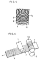
- An electrode group was assembled by spirally rolling up the electrode "d” produced in the above-mentioned manner as the positive electrode, a known nonwoven fabric separator of polypropylene and a known metal hydride negative electrode of a hydrogen storage alloy comprising misch metal and nickel, interposing the separator between both electrodes and placing the positive electrode "d” so that the side provided with the grooves 2 faces outward as shown in FIG. 7. Then, a cylindrical battery (Battery D) was configured with this electrode group in a manner similar to that in Example 1.
- Battery D in accordance with the present invention has improved utilization rate and discharge capacity rate, compared with Battery B of the comparative example.
- the improvement in Battery D is caused by the configuration of its electrode group, because the positive electrode is rolled up together with the negative electrode and the separator in spiral fashion so that one face without filling of the active material faces inward, and the grooves 2 are provided perpendicular to the direction of rolling up of the electrodes so that the grooves 2 are directed toward the outer periphery.
- This configuration improves the conductivity of the positive electrode by the inner face with increased conductivity of the porous metal substrate and the substantial area for the electrode reaction.
- Example 1 A procedure similar to that in Example 1 was generally followed and the same prescription of the paste as that of Example 1 was adopted for producing another nickel electrode.
- a plurality of grooves 2 were provided on one face (bottom side) of the belt-like foamed nickel porous substrate along its lengthwise direction, by transferring the belt-like foamed nickel substrate between a ribbed roller 5a provided on one face (bottom side) of the substrate and a follower roller 6 provided on the other face (top side) of the substrate, respectively, and by pressing the substrate 1 with both rollers from both sides.
- the paste was allowed to spout out through the nozzle 3 onto one face (top side) of the porous substrate 1 to be filled into the spaces of the substrate 1.
- an electrode was produced in the same manner as that in Example 1. This was named electrode "e”.
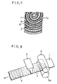
- An electrode group was assembled by spirally rolling up the electrode "e” produced in the above-mentioned manner as the positive electrode, a known separator and a known metal hydride negative electrode of a hydrogen storage alloy comprising misch metal and nickel, interposing a separator between both electrodes and placing the positive electrode "e” so that the side provided with the grooves 2 faces outward as shown in FIG. 9. Then, a cylindrical battery (Battery E) was configured with this electrode group in a manner similar to that in Example 1. For 100 examples of each of Battery E and Battery B as the comparative sample, the utilization rate of the positive electrode and the discharge capacity rate were measured. The results of the measurements are summarized in Table 3 below. Table 3 Utilization rate of the positive electrode Discharge capacity rate Battery B 93.5% 91.0% Battery E 97.0% 93.5%
- Battery E in accordance with the present invention has improved utilization rate and discharge capacity rate, compared with Battery B of the comparative example.
- the improvement in Battery E is caused by the configuration of its electrode group, because the positive electrode is rolled up together with the negative electrode and the separator in spiral fashion so that one face without filling of active material faces outward, and the grooves 2 are provided perpendicular to the direction of rolling up of the electrodes.
- the cylindrical electrode group could have a cross-section of preferably a true circle. This configuration improves the conductivity of the positive electrode by the outer face with increased conductivity of the porous metal substrate and the efficiency of the reactivity with the negative electrode.
- the descriptions are limited to the use of the foamed nickel as the porous metal substrate; it is needless to say that the technical advantages similar to those with the foamed nickel can also be obtained if a nonwoven fabric of nickel fibers and a sintered plaque of nickel powder without skeletal structure are employed for fabricating the electrode, as far as these substrates have the three-dimensional communicating spaces.
Landscapes
- Chemical & Material Sciences (AREA)
- Chemical Kinetics & Catalysis (AREA)
- Electrochemistry (AREA)
- General Chemical & Material Sciences (AREA)
- Engineering & Computer Science (AREA)
- Manufacturing & Machinery (AREA)
- Cell Electrode Carriers And Collectors (AREA)
- Battery Electrode And Active Subsutance (AREA)
- Secondary Cells (AREA)
Applications Claiming Priority (6)
| Application Number | Priority Date | Filing Date | Title |
|---|---|---|---|
| JP11044295 | 1995-05-09 | ||
| JP110442/95 | 1995-05-09 | ||
| JP11044295 | 1995-05-09 | ||
| JP7263758A JP2973894B2 (ja) | 1995-05-09 | 1995-10-12 | 円筒型電池 |
| JP263758/95 | 1995-10-12 | ||
| JP26375895 | 1995-10-12 |
Publications (2)
| Publication Number | Publication Date |
|---|---|
| EP0742601A1 true EP0742601A1 (de) | 1996-11-13 |
| EP0742601B1 EP0742601B1 (de) | 2000-06-14 |
Family
ID=26450071
Family Applications (1)
| Application Number | Title | Priority Date | Filing Date |
|---|---|---|---|
| EP96302727A Expired - Lifetime EP0742601B1 (de) | 1995-05-09 | 1996-04-18 | Zylindrische Batterie mit spiralförmig gewickelten Elektrodenblock |
Country Status (5)
| Country | Link |
|---|---|
| US (1) | US5637416A (de) |
| EP (1) | EP0742601B1 (de) |
| JP (1) | JP2973894B2 (de) |
| CN (1) | CN1078752C (de) |
| DE (1) | DE69608849T2 (de) |
Cited By (2)
| Publication number | Priority date | Publication date | Assignee | Title |
|---|---|---|---|---|
| EP1056144A3 (de) * | 1999-05-26 | 2006-09-20 | Sumitomo Electric Industries, Ltd. | Metallischer poröser Körper, Herstellungsverfahren und Strömkollektor für Batterie |
| EP1117139A4 (de) * | 1999-07-21 | 2007-03-28 | Matsushita Electric Industrial Co Ltd | Polplatte für alkalische speicherbatterie und herstellung dieser polplatte und alkalische speicherbatterie |
Families Citing this family (22)
| Publication number | Priority date | Publication date | Assignee | Title |
|---|---|---|---|---|
| US5849430A (en) * | 1995-05-31 | 1998-12-15 | Samsung Display Devices Co., Ltd. | Structure of an electrode of a secondary battery |
| US5981108A (en) * | 1995-10-09 | 1999-11-09 | Matsushita Electric Industrial Co, Ltd. | Electrodes for battery and method of fabricating the same |
| KR100189808B1 (ko) * | 1996-06-10 | 1999-06-01 | 손욱 | 권취 극판군 |
| KR100210502B1 (ko) * | 1996-06-19 | 1999-07-15 | 손욱 | 권취극판군용 세퍼레이터 |
| JP3412437B2 (ja) * | 1997-02-10 | 2003-06-03 | 松下電器産業株式会社 | アルカリ蓄電池 |
| US6287719B1 (en) * | 1998-06-15 | 2001-09-11 | Eveready Battery Company, Inc. | Battery including a non-aqueous multi-cell spiral-wound electrode assembly |
| JP2000285956A (ja) * | 1999-03-30 | 2000-10-13 | Sanyo Electric Co Ltd | 円筒型アルカリ蓄電池 |
| JP2000357519A (ja) * | 1999-06-15 | 2000-12-26 | Katayama Tokushu Kogyo Kk | 金属多孔体、該金属多孔体からなる電池用電極板、および該電極板を備えた電池 |
| KR100305350B1 (ko) * | 1999-07-01 | 2001-11-01 | 이계안 | Ni-MH 전지의 음극판 조립장치 및 그 공정 |
| US6479188B1 (en) | 1999-10-13 | 2002-11-12 | The Gillette Company | Cathode tube and method of making the same |
| JP4772185B2 (ja) * | 2000-12-12 | 2011-09-14 | パナソニック株式会社 | アルカリ蓄電池用正極板およびその製造方法ならびにそれを用いたアルカリ蓄電池 |
| JP4179943B2 (ja) * | 2003-08-04 | 2008-11-12 | 三洋電機株式会社 | 円筒型アルカリ蓄電池 |
| US7846574B2 (en) | 2004-08-27 | 2010-12-07 | Panosonic Corporation | Positive electrode plate for alkaline storage battery and method for producing the same |
| US10418647B2 (en) | 2015-04-15 | 2019-09-17 | Lockheed Martin Energy, Llc | Mitigation of parasitic reactions within flow batteries |
| KR20180042852A (ko) | 2015-08-19 | 2018-04-26 | 록히드 마틴 에너지, 엘엘씨 | 플로우 배터리 내의 고형물 저감 방법 |
| US10381674B2 (en) | 2016-04-07 | 2019-08-13 | Lockheed Martin Energy, Llc | High-throughput manufacturing processes for making electrochemical unit cells and electrochemical unit cells produced using the same |
| US10147957B2 (en) | 2016-04-07 | 2018-12-04 | Lockheed Martin Energy, Llc | Electrochemical cells having designed flow fields and methods for producing the same |
| US10109879B2 (en) * | 2016-05-27 | 2018-10-23 | Lockheed Martin Energy, Llc | Flow batteries having an electrode with a density gradient and methods for production and use thereof |
| US10403911B2 (en) | 2016-10-07 | 2019-09-03 | Lockheed Martin Energy, Llc | Flow batteries having an interfacially bonded bipolar plate-electrode assembly and methods for production and use thereof |
| US10573899B2 (en) | 2016-10-18 | 2020-02-25 | Lockheed Martin Energy, Llc | Flow batteries having an electrode with differing hydrophilicity on opposing faces and methods for production and use thereof |
| US10581104B2 (en) | 2017-03-24 | 2020-03-03 | Lockheed Martin Energy, Llc | Flow batteries having a pressure-balanced electrochemical cell stack and associated methods |
| CN109244371B (zh) * | 2018-10-16 | 2024-02-27 | 深圳吉阳智能科技有限公司 | 电池极片热复合设备 |
Citations (9)
| Publication number | Priority date | Publication date | Assignee | Title |
|---|---|---|---|---|
| FR2087324A5 (de) * | 1970-05-14 | 1971-12-31 | Wonder | |
| JPS55108182A (en) * | 1979-02-14 | 1980-08-19 | Furukawa Battery Co Ltd:The | Alkali storage battery |
| US4251603A (en) * | 1980-02-13 | 1981-02-17 | Matsushita Electric Industrial Co., Ltd. | Battery electrode |
| JPS58161251A (ja) * | 1982-03-19 | 1983-09-24 | Japan Storage Battery Co Ltd | アルカリ電池用渦巻状正極板の製造法 |
| JPS59207560A (ja) * | 1983-05-11 | 1984-11-24 | Matsushita Electric Ind Co Ltd | 電池用電極の製造法 |
| JPS60133655A (ja) * | 1983-12-21 | 1985-07-16 | Matsushita Electric Ind Co Ltd | 円筒密閉型ニツケル−カドミウム蓄電池用正極板 |
| JPS62139256A (ja) * | 1985-12-11 | 1987-06-22 | Matsushita Electric Ind Co Ltd | 密閉型ニツケルカドミウム蓄電池 |
| JPS6381767A (ja) * | 1986-09-26 | 1988-04-12 | Matsushita Electric Ind Co Ltd | 電池用電極とその製造方法 |
| WO1994013025A1 (en) * | 1992-11-20 | 1994-06-09 | National-Standard Company | Battery electrode substrates and methods of making the same |
Family Cites Families (4)
| Publication number | Priority date | Publication date | Assignee | Title |
|---|---|---|---|---|
| US3314821A (en) * | 1964-02-28 | 1967-04-18 | Sylvania Electric Prod | Storage battery electrode of sintered metal particles |
| JP2762782B2 (ja) * | 1991-08-02 | 1998-06-04 | 松下電器産業株式会社 | 密閉電池 |
| US5487961A (en) * | 1992-04-24 | 1996-01-30 | Eveready Battery Company, Inc. | Sintered metal electrode |
| JP2639620B2 (ja) * | 1993-10-13 | 1997-08-13 | 古河電池株式会社 | 水素吸蔵合金電極の製造方法 |
-
1995
- 1995-10-12 JP JP7263758A patent/JP2973894B2/ja not_active Expired - Fee Related
-
1996
- 1996-03-19 US US08/618,644 patent/US5637416A/en not_active Expired - Fee Related
- 1996-04-18 DE DE69608849T patent/DE69608849T2/de not_active Expired - Fee Related
- 1996-04-18 EP EP96302727A patent/EP0742601B1/de not_active Expired - Lifetime
- 1996-05-09 CN CN96106236A patent/CN1078752C/zh not_active Expired - Fee Related
Patent Citations (9)
| Publication number | Priority date | Publication date | Assignee | Title |
|---|---|---|---|---|
| FR2087324A5 (de) * | 1970-05-14 | 1971-12-31 | Wonder | |
| JPS55108182A (en) * | 1979-02-14 | 1980-08-19 | Furukawa Battery Co Ltd:The | Alkali storage battery |
| US4251603A (en) * | 1980-02-13 | 1981-02-17 | Matsushita Electric Industrial Co., Ltd. | Battery electrode |
| JPS58161251A (ja) * | 1982-03-19 | 1983-09-24 | Japan Storage Battery Co Ltd | アルカリ電池用渦巻状正極板の製造法 |
| JPS59207560A (ja) * | 1983-05-11 | 1984-11-24 | Matsushita Electric Ind Co Ltd | 電池用電極の製造法 |
| JPS60133655A (ja) * | 1983-12-21 | 1985-07-16 | Matsushita Electric Ind Co Ltd | 円筒密閉型ニツケル−カドミウム蓄電池用正極板 |
| JPS62139256A (ja) * | 1985-12-11 | 1987-06-22 | Matsushita Electric Ind Co Ltd | 密閉型ニツケルカドミウム蓄電池 |
| JPS6381767A (ja) * | 1986-09-26 | 1988-04-12 | Matsushita Electric Ind Co Ltd | 電池用電極とその製造方法 |
| WO1994013025A1 (en) * | 1992-11-20 | 1994-06-09 | National-Standard Company | Battery electrode substrates and methods of making the same |
Non-Patent Citations (6)
| Title |
|---|
| CHEMICAL ABSTRACTS, vol. 109, no. 8, 22 August 1988, Columbus, Ohio, US; abstract no. 58216, TSUDA SHINGO ET AL: "Battery electrodes and their manufacture" XP002011553 * |
| PATENT ABSTRACTS OF JAPAN vol. 004, no. 157 (E - 032) 4 November 1980 (1980-11-04) * |
| PATENT ABSTRACTS OF JAPAN vol. 007, no. 280 (E - 216) 14 December 1983 (1983-12-14) * |
| PATENT ABSTRACTS OF JAPAN vol. 009, no. 069 (E - 305) 29 March 1985 (1985-03-29) * |
| PATENT ABSTRACTS OF JAPAN vol. 009, no. 295 (E - 360) 21 November 1985 (1985-11-21) * |
| PATENT ABSTRACTS OF JAPAN vol. 011, no. 367 (E - 561) 28 November 1987 (1987-11-28) * |
Cited By (2)
| Publication number | Priority date | Publication date | Assignee | Title |
|---|---|---|---|---|
| EP1056144A3 (de) * | 1999-05-26 | 2006-09-20 | Sumitomo Electric Industries, Ltd. | Metallischer poröser Körper, Herstellungsverfahren und Strömkollektor für Batterie |
| EP1117139A4 (de) * | 1999-07-21 | 2007-03-28 | Matsushita Electric Industrial Co Ltd | Polplatte für alkalische speicherbatterie und herstellung dieser polplatte und alkalische speicherbatterie |
Also Published As
| Publication number | Publication date |
|---|---|
| DE69608849D1 (de) | 2000-07-20 |
| CN1138218A (zh) | 1996-12-18 |
| EP0742601B1 (de) | 2000-06-14 |
| JPH0927342A (ja) | 1997-01-28 |
| US5637416A (en) | 1997-06-10 |
| DE69608849T2 (de) | 2001-02-01 |
| CN1078752C (zh) | 2002-01-30 |
| JP2973894B2 (ja) | 1999-11-08 |
Similar Documents
| Publication | Publication Date | Title |
|---|---|---|
| EP0742601B1 (de) | Zylindrische Batterie mit spiralförmig gewickelten Elektrodenblock | |
| US5585142A (en) | Method for preparing conductive electrochemically active material | |
| US6800399B2 (en) | Non-sintered thin electrode for battery, battery using same and process for same | |
| US4460666A (en) | Coated substrate, preparation thereof, and use thereof | |
| EP1082768B1 (de) | Nichtgesinterte elektrode und verfahren zur herstellung | |
| US7378182B2 (en) | Cylindrical alkaline storage battery | |
| EP0409616A1 (de) | Gewickelte Elektrodenanordnung für eine elektrochemische Zelle | |
| EP0384945B1 (de) | Gasdichte alkalische Sammlerbatterie und Verfahren zur Herstellung der negativen Elektrode davon | |
| EP4383369A2 (de) | Negativelektrode für eine zinkbatterie und verfahren zur herstellung davon | |
| EP0436004B1 (de) | Wiederaufladbare nickelelektrode mit elektrochemischer zelle und verfahren zu deren herstellung | |
| US6051333A (en) | Cell comprising spirally wound electrodes | |
| KR20020053807A (ko) | 재 충전식 니켈-아연 전지 | |
| EP0301647B1 (de) | Elektrochemische Zelle | |
| EP1498977A1 (de) | Alkalin-speicherbatterie | |
| EP1215741B1 (de) | Verfahren zur Herstellung einer positiven Elecktrodenplatte | |
| JP2002260628A (ja) | アルカリ二次電池用正極、アルカリ二次電池用正極の製造方法及びアルカリ二次電池 | |
| US3347707A (en) | Charged secondary cell | |
| EP0742600A1 (de) | Batterieelektroden und Verfahren zur Herstellung | |
| EP0800221A1 (de) | Alkalische Speicherbatterie und Verfahren zur Herstellung von positiver Elektrodenplatte dafür | |
| EP0599603A1 (de) | Metalhydridelektrode, Zelle und Verfahren zu ihrer Herstellung | |
| JP3973115B2 (ja) | 巻回構造の電極体を有する電池 | |
| JP2926233B2 (ja) | アルカリ二次電池の製造方法 | |
| JPH09190836A5 (de) | ||
| CN1079844A (zh) | 镍-氢化物碱性蓄电池及其制造方法 | |
| JP3504303B2 (ja) | 円筒形アルカリ二次電池 |
Legal Events
| Date | Code | Title | Description |
|---|---|---|---|
| PUAI | Public reference made under article 153(3) epc to a published international application that has entered the european phase |
Free format text: ORIGINAL CODE: 0009012 |
|
| 17P | Request for examination filed |
Effective date: 19960502 |
|
| AK | Designated contracting states |
Kind code of ref document: A1 Designated state(s): BE DE FR GB |
|
| 17Q | First examination report despatched |
Effective date: 19980526 |
|
| GRAG | Despatch of communication of intention to grant |
Free format text: ORIGINAL CODE: EPIDOS AGRA |
|
| GRAG | Despatch of communication of intention to grant |
Free format text: ORIGINAL CODE: EPIDOS AGRA |
|
| GRAH | Despatch of communication of intention to grant a patent |
Free format text: ORIGINAL CODE: EPIDOS IGRA |
|
| GRAH | Despatch of communication of intention to grant a patent |
Free format text: ORIGINAL CODE: EPIDOS IGRA |
|
| GRAA | (expected) grant |
Free format text: ORIGINAL CODE: 0009210 |
|
| AK | Designated contracting states |
Kind code of ref document: B1 Designated state(s): BE DE FR GB |
|
| REF | Corresponds to: |
Ref document number: 69608849 Country of ref document: DE Date of ref document: 20000720 |
|
| ET | Fr: translation filed | ||
| PLBE | No opposition filed within time limit |
Free format text: ORIGINAL CODE: 0009261 |
|
| STAA | Information on the status of an ep patent application or granted ep patent |
Free format text: STATUS: NO OPPOSITION FILED WITHIN TIME LIMIT |
|
| 26N | No opposition filed | ||
| REG | Reference to a national code |
Ref country code: GB Ref legal event code: IF02 |
|
| PGFP | Annual fee paid to national office [announced via postgrant information from national office to epo] |
Ref country code: FR Payment date: 20060410 Year of fee payment: 11 |
|
| PGFP | Annual fee paid to national office [announced via postgrant information from national office to epo] |
Ref country code: GB Payment date: 20060412 Year of fee payment: 11 |
|
| PGFP | Annual fee paid to national office [announced via postgrant information from national office to epo] |
Ref country code: DE Payment date: 20060413 Year of fee payment: 11 |
|
| PGFP | Annual fee paid to national office [announced via postgrant information from national office to epo] |
Ref country code: BE Payment date: 20060616 Year of fee payment: 11 |
|
| GBPC | Gb: european patent ceased through non-payment of renewal fee |
Effective date: 20070418 |
|
| BERE | Be: lapsed |
Owner name: *MATSUSHITA ELECTRIC INDUSTRIAL CO. LTD Effective date: 20070430 |
|
| PG25 | Lapsed in a contracting state [announced via postgrant information from national office to epo] |
Ref country code: DE Free format text: LAPSE BECAUSE OF NON-PAYMENT OF DUE FEES Effective date: 20071101 |
|
| PG25 | Lapsed in a contracting state [announced via postgrant information from national office to epo] |
Ref country code: BE Free format text: LAPSE BECAUSE OF NON-PAYMENT OF DUE FEES Effective date: 20070430 |
|
| PG25 | Lapsed in a contracting state [announced via postgrant information from national office to epo] |
Ref country code: GB Free format text: LAPSE BECAUSE OF NON-PAYMENT OF DUE FEES Effective date: 20070418 |
|
| PG25 | Lapsed in a contracting state [announced via postgrant information from national office to epo] |
Ref country code: FR Free format text: LAPSE BECAUSE OF NON-PAYMENT OF DUE FEES Effective date: 20070430 |