EP0742624A1 - Dispositif d'introduction d'un faisceau de câbles dans un conduit de protection en matière plastique - Google Patents
Dispositif d'introduction d'un faisceau de câbles dans un conduit de protection en matière plastique Download PDFInfo
- Publication number
- EP0742624A1 EP0742624A1 EP95106562A EP95106562A EP0742624A1 EP 0742624 A1 EP0742624 A1 EP 0742624A1 EP 95106562 A EP95106562 A EP 95106562A EP 95106562 A EP95106562 A EP 95106562A EP 0742624 A1 EP0742624 A1 EP 0742624A1
- Authority
- EP
- European Patent Office
- Prior art keywords
- conduit
- spreader body
- cables
- bundle
- output portion
- Prior art date
- Legal status (The legal status is an assumption and is not a legal conclusion. Google has not performed a legal analysis and makes no representation as to the accuracy of the status listed.)
- Withdrawn
Links
- 230000001681 protective effect Effects 0.000 title claims abstract description 16
- 239000000463 material Substances 0.000 title claims abstract description 7
- 229920003023 plastic Polymers 0.000 title claims abstract description 6
- 239000004033 plastic Substances 0.000 title claims abstract description 6
- 230000000452 restraining effect Effects 0.000 claims description 19
- 230000037431 insertion Effects 0.000 description 5
- 238000003780 insertion Methods 0.000 description 5
- 230000001413 cellular effect Effects 0.000 description 2
- 230000000694 effects Effects 0.000 description 2
- 229920000114 Corrugated plastic Polymers 0.000 description 1
- 239000002390 adhesive tape Substances 0.000 description 1
- 239000003795 chemical substances by application Substances 0.000 description 1
Images



Classifications
-
- H—ELECTRICITY
- H02—GENERATION; CONVERSION OR DISTRIBUTION OF ELECTRIC POWER
- H02G—INSTALLATION OF ELECTRIC CABLES OR LINES, OR OF COMBINED OPTICAL AND ELECTRIC CABLES OR LINES
- H02G1/00—Methods or apparatus specially adapted for installing, maintaining, repairing or dismantling electric cables or lines
- H02G1/06—Methods or apparatus specially adapted for installing, maintaining, repairing or dismantling electric cables or lines for laying cables, e.g. laying apparatus on vehicle
- H02G1/08—Methods or apparatus specially adapted for installing, maintaining, repairing or dismantling electric cables or lines for laying cables, e.g. laying apparatus on vehicle through tubing or conduit, e.g. rod or draw wire for pushing or pulling
Definitions
- the present invention relates to a device for inserting a bundle of cables into a protective conduit of plastics material having a longitudinal through slot.
- a typical field of application of the device according to the invention is that of the preparation of wiring harnesses for the automotive industry.
- the wiring harnesses which interconnect the various electrical devices of a vehicle and the switching and control devices are generally prepared off the vehicle-assembly line and are provided with quick-fit connectors.
- a particularly important aspect for the purposes of the reliability of the wiring harness is that of the mechanical protection of the cables.
- no particular precautions are taken to protect the wiring harness, and localized binding is simply carried out by means of adhesive tapes or the like having the purpose simply of holding the wiring harness in a certain position, no care being taken to provide mechanical protection against outside agents.
- protective conduits of plastics material for example, of the corrugated type, for protecting electrical cables is already known.
- Protective conduits having longitudinal through slots for enabling cables or wiring harnesses to be inserted in the respective protective conduit even when the cables are fixed permanently to connectors which would not be able to pass through the conduit are also known.
- the use of protective conduits of plastics material in the automotive industry is not very widespread, particularly because of the large amount of time required for the operations to insert wiring harnesses inside protective conduits and the high cost which these operations involve.
- the object of the present invention is to provide a device which enables the operation of inserting a bundle of cables in a protective conduit having a longitudinal slot to be carried out easily and quickly.
- this object is achieved by a device having the characteristics which form the subject of Claim 1.
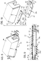
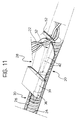
- FIG. 8-11 in which the device according to the invention, indicated 20, is shown separately from the rest of the equipment as a whole.
- the device 20 serves to insert a wiring harness 22 ( Figures 9 and 11) into a protective conduit 24 of corrugated plastics material having a longitudinal through slot 26.
- the device 20 comprises a spreader body 28 having an input portion 30 and an output portion 32.
- the spreader body 28 is constituted by two parts indicated 28a and 28b; however, this characteristic is not essential for the purposes of the present invention and the spreader body may be formed in a single piece, the functionality of the device remaining unchanged.
- the first part 28a has a substantially cylindrical element 34 with a tapered end 36.
- the cylindrical element 34 is spaced from a flat base 38 and is connected thereto by means of a rib 40.
- the second part 28b of the spreader body 28 has two diverging spreader walls 42 between which is defined a through channel 44 which is wider in the output portion 32.
- the device 20 also comprises an element 46 with a channel section, to which the parts 28a and 28b of the spreader body 28 are fixed.
- the element 46 in combination with the spreader body 28, defines a duct 48 through which the conduit 24 is free to slide in the direction indicated by the arrow 50.
- the conduit 24 is inserted in the duct 48 by hand, starting from the input portion 30.
- the tapered end 36 of the element 34 centres the conduit.
- the longitudinal slot 26 in the conduit 24 has to be positioned adjacent the rib 40 so that the rib 40 is inserted in the slot 26 when the conduit 24 is urged into the duct 48.
- the cylindrical element 34 is placed inside the conduit and has a restraining and guiding effect on the internal surface of the conduit 24.
- the channel element 46 on the other hand, has a restraining and guiding effect on the outer surface of the conduit 24.
- the device described hitherto thus enables the portion of the conduit 24 which is in the output portion 32 at any particular time to be opened out resiliently by virtue of a relative movement between the spreader body 28 and the conduit 24.
- the restraining member 52 is constituted simply by a pin or bar which extends in front of the output portion 32 transverse the spreader walls 42.
- the member 52 is preferably movable between a retracted, inoperative position and an operative, restraining position in which it is situated in the position shown in Figure 9.
- a space is defined between the restraining member 52 and the front ends of the spreader walls 42 and the wiring harness 22 extends therein.
- the conduit 24 moves in the direction indicated by the arrow 50 in Figure 9, it slides over the outer surface of the restraining member 52 and undergoes slight resilient deformation in order to follow the deviation imposed by the presence of the restraining member 52.
- the device 20 is carried in a stationary manner by a base 54 having a lever mechanism 56 which controls the movement of the restraining member 52 between the operative and inoperative positions. Pivoting of the lever 58 in the senses indicated by the double arrow 60 moves the restraining member 52 in the directions indicated by the double arrow 62.
- the restraining member 52 is brought to an inoperative position by the operation of the lever 58 so as to leave the region in front of the output portion of the device 20 clear.
- the wiring harness 22 is positioned on the base 54 between stationary locating projections 64 so that it extends in front of the output portion of the device 20.
- the lever 60 is operated to bring the restraining member 52 to the operative position.
- Figure 1 shows the equipment upon completion of this step, when the wiring harness 22 is ready for insertion in a protective conduit.
- the protective conduit 24 is passed through the device 20 from the input portion of the device, which is in the rear portion of the equipment in the view of Figure 2.
- the conduit 24 is advanced in the direction indicated by the arrow 66, both the equipment and the wiring harness 22 being kept stationary.
- the wiring harness 22 is introduced progressively into the conduit 24 through the opened-out portion of the slot 26. Insertion in the conduit is completed when the entire length of the protective conduit 24 has passed through the device 20.
- the device 20 is associated with a device 70 for preparing and checking wiring harnesses 22 associated with cellular connectors 72.
- the device 70 is of known type and comprises a seat 74 for housing and restraining a cellular connector 72 during the operations to prepare and/or check the wiring harness.
- the connector 72 is already connected to the end of the wiring harness 22, but this connection will generally take place whilst the connector 72 is restrained in the seat 74 in the device 70.
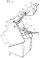
- the equipment is as shown in Figure 4, with the connector 72 locked in the seat in the device 70.
- the device 70 for preparing and checking the wiring harnesses is carried in a stationary manner by a base 76 to which a box flange 78, which carries the device 20 so that it can pivot about an axis 79, is fixed.
- the device 20 In the position shown in Figures 3 and 4, the device 20 is in an inoperative position.
- An extension 81 which is in a stationary position relative to the device 20, carries a tubular guide 83 in which the member 52 which restrains the wiring harness 22 is movable.
- the restraining member 52 can slide inside the tubular guide 83 and is operated by a push-button 80 movable in the directions indicated by the double arrow 82.
- the device 20 is brought to the operative position by a pivoting movement about the axis 79.
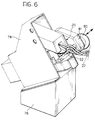
- the wiring harness 22 is then positioned adjacent the output portion of the device 20 and the retaining member 52 is brought to the operative position by the operation of the push-button 80.
- the wiring harness 22 is then in the configuration shown in Figure 6, relative to the device 20.
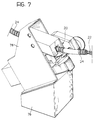
- a protective conduit 24 is then introduced, starting from the input portion of the device 20, as shown in Figure 7, by being advanced manually in the direction indicated by the arrow 84 in Figure 7.
- the wiring harness 22 is also inserted in the conduit 24 progressively as the conduit gradually passes through the device 20. When the entire length of the conduit has passed through the device 20, the insertion of the wiring harness 22 will be complete.
Landscapes
- Installation Of Indoor Wiring (AREA)
Priority Applications (1)
| Application Number | Priority Date | Filing Date | Title |
|---|---|---|---|
| EP95106562A EP0742624A1 (fr) | 1995-05-02 | 1995-05-02 | Dispositif d'introduction d'un faisceau de câbles dans un conduit de protection en matière plastique |
Applications Claiming Priority (1)
| Application Number | Priority Date | Filing Date | Title |
|---|---|---|---|
| EP95106562A EP0742624A1 (fr) | 1995-05-02 | 1995-05-02 | Dispositif d'introduction d'un faisceau de câbles dans un conduit de protection en matière plastique |
Publications (1)
| Publication Number | Publication Date |
|---|---|
| EP0742624A1 true EP0742624A1 (fr) | 1996-11-13 |
Family
ID=8219212
Family Applications (1)
| Application Number | Title | Priority Date | Filing Date |
|---|---|---|---|
| EP95106562A Withdrawn EP0742624A1 (fr) | 1995-05-02 | 1995-05-02 | Dispositif d'introduction d'un faisceau de câbles dans un conduit de protection en matière plastique |
Country Status (1)
| Country | Link |
|---|---|
| EP (1) | EP0742624A1 (fr) |
Cited By (1)
| Publication number | Priority date | Publication date | Assignee | Title |
|---|---|---|---|---|
| FR2761826A1 (fr) * | 1997-04-04 | 1998-10-09 | Bentley Harris Sa | Outil et procede de gainage de cables |
Citations (4)
| Publication number | Priority date | Publication date | Assignee | Title |
|---|---|---|---|---|
| FR2497011A1 (fr) * | 1980-12-18 | 1982-06-25 | Gautier Georges | Procede et appareil pour constituer un chemin de cables du genre conduit tubulaire fendu longitudinalement |
| US4593442A (en) * | 1985-06-17 | 1986-06-10 | Wright Curtis M | Cable installation apparatus |
| EP0248250A1 (fr) * | 1986-05-21 | 1987-12-09 | Tirfibre S.A. | Procédé de pose et de tirage d'un câble dans un conduit et installation pour la mise en oeuvre de ce procédé |
| EP0531150A2 (fr) * | 1991-09-04 | 1993-03-10 | Sumitomo Wiring Systems, Ltd. | Dispositif d'installation de tubes à soufflets |
-
1995
- 1995-05-02 EP EP95106562A patent/EP0742624A1/fr not_active Withdrawn
Patent Citations (4)
| Publication number | Priority date | Publication date | Assignee | Title |
|---|---|---|---|---|
| FR2497011A1 (fr) * | 1980-12-18 | 1982-06-25 | Gautier Georges | Procede et appareil pour constituer un chemin de cables du genre conduit tubulaire fendu longitudinalement |
| US4593442A (en) * | 1985-06-17 | 1986-06-10 | Wright Curtis M | Cable installation apparatus |
| EP0248250A1 (fr) * | 1986-05-21 | 1987-12-09 | Tirfibre S.A. | Procédé de pose et de tirage d'un câble dans un conduit et installation pour la mise en oeuvre de ce procédé |
| EP0531150A2 (fr) * | 1991-09-04 | 1993-03-10 | Sumitomo Wiring Systems, Ltd. | Dispositif d'installation de tubes à soufflets |
Cited By (3)
| Publication number | Priority date | Publication date | Assignee | Title |
|---|---|---|---|---|
| FR2761826A1 (fr) * | 1997-04-04 | 1998-10-09 | Bentley Harris Sa | Outil et procede de gainage de cables |
| WO1998045914A1 (fr) * | 1997-04-04 | 1998-10-15 | Federal-Mogul Systems Protection Group S.A.S. | Outil et procede servant a gainer des cables |
| US6550137B1 (en) | 1997-04-04 | 2003-04-22 | Federal-Mogul Systems Protection Group S.A.S. | Tool and method for sheathing of cables |
Similar Documents
| Publication | Publication Date | Title |
|---|---|---|
| CA2195515C (fr) | Un connecteur muni d'elements de verrouillage supplementaires | |
| EP1502143B1 (fr) | Raccord pour connecteurs enfichables, dote d'un clapet de securite pouvant etre installe apres coup | |
| KR100282131B1 (ko) | 충전기잠금기구 | |
| US5315062A (en) | Wire harness connector cover | |
| EP0774804B1 (fr) | Connecteur de détection de l'engagement incomplet | |
| KR20190106967A (ko) | 축방향 연결 보조구를 갖는 전기 커넥터 조립체 | |
| CN106655030B (zh) | 缆线端头配件和缆线接合器及其固定方法 | |
| CN210201361U (zh) | 车辆设备 | |
| US20070230889A1 (en) | Plug-in unit | |
| US20070155191A1 (en) | Electric plug comprising a plug housing and at least two integrated plug-in contacts with an ejection mechanism | |
| US6083057A (en) | Electric connector | |
| JP4832389B2 (ja) | 光コネクタ組立治具 | |
| US4414736A (en) | Insertion and extraction tool for connector terminals | |
| US6332791B1 (en) | Card connector with card-ejecting device | |
| AU2006201351B2 (en) | Tooling for manufacturing large-section rigid harnesses | |
| US5957165A (en) | Apparatus for winding and tightening a band clip around a wiring harness | |
| DE102018210306A1 (de) | Steckverbinder | |
| EP4462611A1 (fr) | Connecteur électrique avec dispositif ergonomique d'assistance à l'accouplement axial | |
| SK283844B6 (sk) | Zariadenie na oplášťovanie zväzku vodičov | |
| US6264482B1 (en) | Connector coupling device | |
| KR100978778B1 (ko) | 분리 방지용 콘넥터 | |
| US5873303A (en) | Method for binding bundled objects, in particular pieces of cable, as well as an associated apparatus and a binding material | |
| KR19980018021A (ko) | 차량용 컵홀더 | |
| US5417254A (en) | Binding tool | |
| JP2006313730A (ja) | コネクタ装置 |
Legal Events
| Date | Code | Title | Description |
|---|---|---|---|
| PUAI | Public reference made under article 153(3) epc to a published international application that has entered the european phase |
Free format text: ORIGINAL CODE: 0009012 |
|
| AK | Designated contracting states |
Kind code of ref document: A1 Designated state(s): DE ES FR |
|
| AX | Request for extension of the european patent |
Free format text: LT;SI |
|
| RAX | Requested extension states of the european patent have changed |
Free format text: LT;SI |
|
| RBV | Designated contracting states (corrected) |
Designated state(s): DE ES FR |
|
| STAA | Information on the status of an ep patent application or granted ep patent |
Free format text: STATUS: THE APPLICATION IS DEEMED TO BE WITHDRAWN |
|
| 18D | Application deemed to be withdrawn |
Effective date: 19970514 |