EP0743005A1 - Dispositif pour l'assomage électrique d'animaux de boucherie - Google Patents
Dispositif pour l'assomage électrique d'animaux de boucherie Download PDFInfo
- Publication number
- EP0743005A1 EP0743005A1 EP96107924A EP96107924A EP0743005A1 EP 0743005 A1 EP0743005 A1 EP 0743005A1 EP 96107924 A EP96107924 A EP 96107924A EP 96107924 A EP96107924 A EP 96107924A EP 0743005 A1 EP0743005 A1 EP 0743005A1
- Authority
- EP
- European Patent Office
- Prior art keywords
- electrode
- support
- animal
- rest
- slaughter
- Prior art date
- Legal status (The legal status is an assumption and is not a legal conclusion. Google has not performed a legal analysis and makes no representation as to the accuracy of the status listed.)
- Granted
Links
- 241001465754 Metazoa Species 0.000 claims abstract description 66
- 238000003307 slaughter Methods 0.000 claims abstract description 43
- 241000282887 Suidae Species 0.000 claims abstract description 8
- 210000002784 stomach Anatomy 0.000 claims description 4
- 210000001015 abdomen Anatomy 0.000 abstract description 2
- 210000000115 thoracic cavity Anatomy 0.000 abstract 1
- 210000000038 chest Anatomy 0.000 description 12
- 210000002414 leg Anatomy 0.000 description 6
- 206010002091 Anaesthesia Diseases 0.000 description 5
- 230000037005 anaesthesia Effects 0.000 description 5
- 210000004556 brain Anatomy 0.000 description 5
- 210000000481 breast Anatomy 0.000 description 5
- 230000003444 anaesthetic effect Effects 0.000 description 4
- 210000003128 head Anatomy 0.000 description 4
- 238000012549 training Methods 0.000 description 4
- 238000013461 design Methods 0.000 description 3
- 238000000034 method Methods 0.000 description 3
- 208000003663 ventricular fibrillation Diseases 0.000 description 3
- 230000004888 barrier function Effects 0.000 description 2
- 230000006835 compression Effects 0.000 description 2
- 238000007906 compression Methods 0.000 description 2
- 238000010276 construction Methods 0.000 description 2
- 238000011161 development Methods 0.000 description 2
- 230000018109 developmental process Effects 0.000 description 2
- 230000002349 favourable effect Effects 0.000 description 2
- 230000008569 process Effects 0.000 description 2
- 230000007704 transition Effects 0.000 description 2
- 210000001364 upper extremity Anatomy 0.000 description 2
- 208000010392 Bone Fractures Diseases 0.000 description 1
- 240000006829 Ficus sundaica Species 0.000 description 1
- 208000006670 Multiple fractures Diseases 0.000 description 1
- 239000008280 blood Substances 0.000 description 1
- 210000004369 blood Anatomy 0.000 description 1
- 210000001217 buttock Anatomy 0.000 description 1
- 239000008358 core component Substances 0.000 description 1
- 238000004070 electrodeposition Methods 0.000 description 1
- 230000006870 function Effects 0.000 description 1
- 238000010348 incorporation Methods 0.000 description 1
- 230000009467 reduction Effects 0.000 description 1
- 238000010079 rubber tapping Methods 0.000 description 1
- 210000004894 snout Anatomy 0.000 description 1
- 210000001519 tissue Anatomy 0.000 description 1
Images


Classifications
-
- A—HUMAN NECESSITIES
- A22—BUTCHERING; MEAT TREATMENT; PROCESSING POULTRY OR FISH
- A22B—SLAUGHTERING
- A22B3/00—Slaughtering or stunning
- A22B3/06—Slaughtering or stunning by electric current
Definitions
- the invention relates to a device for electrically stunning animals for slaughter, in particular pigs, which are immobilized with their legs hanging down on their stomach lying on a support, with at least one electrode which is intended to rest in the chest area of the slaughtered animal in each case.
- slaughter animals are mostly anesthetized in an immobilized state, especially because in this state the electrodes with which the anesthetic voltage is applied to the respective slaughter animal can be attached more safely and conveniently and because a more or less largely automated electrical stunning is only possible with immobilized slaughter animals is.
- the invention is based on the object of making available a device of the type mentioned at the outset with an electrode placement which is less expensive in space and is particularly functional in terms of achieving a safe electrode system.
- the device is characterized in that the electrode is incorporated in the support; and that the electrode is movable between a first position in which it projects from the support and a second position in which it projects less from the support than in the first position or is retracted into the support.
- the electrode is inherently located at a point at which the breast area of the slaughter animal in question is directly exposed. In a In the position in which the electrode protrudes from the support, particularly secure contact with the breast area of the slaughtered animal is possible.
- the device according to the invention is characterized in that the electrode - in plan view - is arranged next to the support; and that the electrode is movable between a first position in which it reaches higher than the top of the support and a second position in which it extends less than than in the first position or at least to the level of the top of the support.
- the electrode is also in a position in which it can be brought to bear particularly directly in the chest area of the slaughter animal in question. Since the electrode is arranged on the side next to the support, there is more freedom in constructive training than in the incorporation into the support.
- the present application speaks of a device for electrically stunning animals for slaughter, although - as mentioned above - the passage of current through the heart through the heart of the slaughtered animal in most cases does not, strictly speaking, serve to induce anesthesia of the animal for slaughter, but rather causing ventricular fibrillation.
- the expression used was nevertheless chosen because in the device anesthesia normally takes place in the narrower sense by passing current through the brain and because in common language the application of the electrode in the chest area of the slaughter animal in question and the application of current with the aid of this electrode are still used to stunning the slaughter animal added further sense.
- chest area of the slaughter animal is to be understood very comprehensively in connection with the invention.
- chest area is also intended to refer to the animal sides in the include the front trunk area, and also the front transition from the chest (in the narrower sense) to the shoulder area, but in particular also the area of the armpit including the front access from the shoulder area and the rear access from the side area, as will become clearer below becomes.
- the mobility of the electrode according to the invention is preferably a pivoting mobility or a translational mobility.
- This mobility is structurally particularly easy to manage.
- other movabilities are possible, since functionally it only depends on the presence of the first position and the second position.
- the first position ie “further projecting position” or “further extending position”
- the second position is the working position of the electrode, the electrode being movable into the second position by a slaughtered animal on the support is, preferably against spring force.
- This configuration boils down to the fact that the slaughter animal itself, e.g. B. by the laying process or by a feed movement, which brings the electrode into the working position.
- the electrode movement caused by the slaughter animal in question can, but need not, be used to switch on the current flow through the electrode.
- a movement into the second position against spring force leads to the electrode being advantageously pressed well against the slaughter animal in question.
- the second position is the rest position and the first position and working position of the electrode; and that the electrode can be moved into the first position by a drive, preferably by a cylinder-piston unit.
- This preferred development of the invention boils down to the fact that the electrode is actively moved into the first position (i.e. "further protruding position” or “higher reaching position”). It is advantageous if the first position is not a specific and unchangeable fixed position, but z. B. is reached depending on the respective slaughter animal when a certain contact pressure threshold of the electrode to the slaughter animal is reached with the drive.
- the support can preferably be a conveyor belt for closed circulation.
- the support can preferably be a support bar that can be raised for immobilization.
- B. can be raised in a stunning trap and then lowered or z.
- B. is movable in its longitudinal direction to transport a slaughter animal from an access path into a stunning trap.
- the electrode can, as preferred, be arranged on a carriage which can be moved in synchronism with the support, preferably by an associated drive.
- the feed dog can be stopped for a time phase in which the electrode is brought into contact with a slaughter animal and the power is then switched on.
- moving the electrode is unnecessary or nonsensical, especially in the case of the above-described support bar.
- the electrode is preferably designed and positioned in such a way that, in its working position, it lies against an armpit or the (front or rear) access to an armpit of the slaughtered animal.
- These areas of the slaughter animal have so far not been considered for the electrode system. In connection with the invention, however, these areas are considered to be particularly favorable because, owing to the invention, they are quite easily accessible to the electrode, because there the generally Skin of the slaughtered animals is relatively thin, and because the slaughtered animal hair there is normally not particularly massive.
- not only one electrode is provided for abutment in the chest area of the respective slaughter animal, but two electrodes of this type, which are spaced apart from one another transversely to the longitudinal direction of the support.
- the second electrode can also have one or more of the training features described in the present application.
- the two electrodes are preferably designed, arranged, drivable and the like in a manner analogous to one another, so that if one electrode realizes a specific further training feature, the other electrode also realizes this further training feature.
- the device preferably has additional electrodes for contact in the head area of the slaughtered animal to be anesthetized, so that the anesthesia can first be initiated with current flow through the brain of the slaughtered animal and later the anesthetic process with current flow through the heart of the slaughtered animal continues ventricular fibrillation can be generated.
- a higher voltage in particular in the range from 200 to 300 V
- a lower voltage in particular in the range from 80 to 160 V, for the passage of current through the heart.
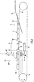
- the stunning device 2 of FIG. 1 has, as the first core component, a lay-on conveyor belt 4 with a closed orbit.
- Fig. 3 illustrates how slaughter animals 6, here a pig, on top of a series of blocks 8, z. B. made of plastic, which are attached to a chain 10 form the lay-up conveyor belt, are lying immobilized lying flat, ie they cannot move down from the lay-up conveyor belt under their own power.
- the pigs 6 arrive in turn on the lay-up conveyor belt 4 by running down a sloping floor 10 which has a central longitudinal slot through which the endless row of blocks 8 comes out.
- a carriage 16 is also schematically indicated, which can be moved forwards and backwards in the longitudinal direction of the conveyor belt 4 and which carries two electrodes 20, which are not shown in Fig. 1 to maintain clarity.
- the design and arrangement of the two electrodes 20 can be clearly seen in FIGS. 2 and 3.
- the two electrodes 20 are of identical design and have an analog function, so that it is sufficient to make the description using one electrode 20.
- the electrode 20 under consideration has an essentially rod-like shape with a rear end region 22 bent downwards. In the bent end region 22, the electrode 20 is mounted on the carriage 16 such that it can pivot about a horizontal axis 24.
- the carriage 16 is approximately as wide in its upper region as the blocks 8 of the lay-on conveyor belt 4 and is located just below the upper run of the conveyor belt 4.
- An electrode 20 is on the left side this upper portion of the carriage 16 and the other electrode 20 is provided on the right side of this upper portion of the carriage 16.
- the electrode 20 At its lower rear end, the electrode 20 under consideration has a cross pin 26 which projects into the interior of the carriage 16 through a slot 28 in the side wall of the upper region of the carriage 16.
- a pneumatic cylinder-piston unit 30 lying in the longitudinal direction of the carriage 16 is connected to the pin 26.
- the main part of the electrode 20 In the state of FIG. 2, the main part of the electrode 20 has a horizontal position.
- the electrode 20 When the cylinder-piston unit 30 is contracted, the electrode 20 is turned clockwise by e.g. B. pivoted 40 to 90 ° so that it extends higher than the top of the blocks 8, s. Fig. 3.
- the two electrodes 20 are provided in mirror image, and it is understood that a cylinder-piston unit 30 is provided for each electrode 20.
- Fig. 3 it can clearly be seen that the electrode 20 under consideration carries out its pivoting movement in a vertical plane which is located between the lateral boundary of the block 8 and the foreleg 32 of the relevant pig 6 which hangs a little apart therefrom. If necessary, this distance can be deliberately increased in that the carriage 16 has a deflector surface for moving the relevant front leg 32 slightly outwards. If the electrode 20 in question is pivoted upwards in the clockwise direction of FIG. 2, it comes at some point with its upper end region to bear against the pig 6 in question, namely in the region of the front or shoulder-side access to the armpit of the pig in question 6.
- Die der Cylinder-piston unit 30 associated with electrode 20 can either be controlled so that it pivots the electrode 20 by a predetermined angle, and / or controlled so that it pivots the electrode 20 until a predetermined contact pressure of the upper electrode area is applied the pig 6 is reached.
- the carriage 16 In its lower area, where it can no longer collide with the legs 32 of pigs 6, the carriage 16 is widened and provided with laterally projecting, rotatable rollers 34.
- the rollers 34 run in rails 36 which have a U-shaped, laterally open cross section.
- the rails 36 run parallel to the upper run of the conveyor belt 4 in the longitudinal direction thereof.
- a light barrier 40 or a light curtain At a certain point along the path of movement of the upper run of the conveyor belt 4 there is a light barrier 40 or a light curtain.
- a pig 6 reaches the light barrier 40 with its snout, this provides sufficiently precise information that the armpits 42 of this pig 6 are at a certain point along the path of movement of the conveyor belt 4 are located.
- the carriage 16 At this time the carriage 16 is in a rest position which matches the position of the armpits 42 in the sense to be described in more detail.
- the control of the anesthetic device 2 gives a command to a traversing drive, preferably in the form of a cylinder-piston unit 44, of the carriage 16 and the two cylinder-piston units are operated practically simultaneously (could also be shortly before or shortly thereafter).
- Units 30 activated for the two electrodes 20.
- the mentioned rest position of the carriage 16 and the timing are coordinated so that the electrodes 20 are in contact with the armpit area 42 of the pig in question after their pivoting movement and that the carriage 16 moves synchronously with the upper run of the conveyor belt 4.
- An electric current flows through the pig's body in an optimally short way, but through the heart area of the pig. This current is allowed to flow for a few seconds, then the electrodes 20 are pivoted back into the position shown in FIG. 2 and the carriage 16 is stopped from its driven forward movement. Thereafter, the cylinder-piston unit 44 performs a rapid return movement of the carriage 16 into its described rest position. The cycle described is repeated with the next pig 6.
- a translational extension z. B. can be provided in the direction obliquely-back-up by means of a cylinder-piston unit.
- the pivoted-out electrode position was the working position in which current was then switched on.
- the construction can also be reversed, as it were, by z. B. instead of the cylinder-piston unit 30 installs a tension spring which normally holds the electrode 20 in an upward-carrying position.
- a pig 6 arriving on the conveyor belt 4 can be the one in question Take the electrode 20 counter-clockwise to the front-down, whereby a contact force builds up between the electrode and the pig because of the tension spring. After a contact force of sufficient size has been reached, the travel drive of the carriage 16 is activated. In this case, the less high position of the electrode 20 is the working position in which current is supplied.
- the support for the slaughtered animal to be anesthetized is formed by a support bar 50.
- a slaughter animal which lies on its stomach with its legs hanging down on the upper side of the support bar 50, is in an immobilized state, the pig extending with its longitudinal direction in the longitudinal direction of the support bar 50.
- the z. B. on vertical columns 52 supported support bar 50 to be raised and lowered in the vertical direction, preferably by means of a cylinder-piston unit, not shown. Then you can e.g. B. Raise the support bar 50 under a pig and immobilize this pig by carrying it upwards.
- the support bar 50 movable in its longitudinal direction by means of a drive, preferably in order to bring a slaughtered animal immobilized thereon into a stunning trap in a manner which is particularly gentle on the animals.
- a drive preferably in order to bring a slaughtered animal immobilized thereon into a stunning trap in a manner which is particularly gentle on the animals.
- two electrodes 20 are embedded in the top of the support bar 50, namely an electrode 20 adjacent to the left edge of the bar 50 and an electrode 20 adjacent to the right edge of the bar 50. Both electrodes 20 run in the longitudinal direction of the beam 50 and are provided at such a location and in such a length that a Slaughter animal of normal length comes to rest with its chest area on the electrodes 20.
- Fig. 4 it can be seen that by means of an actuating piece 54 common to both electrodes 20, which can be moved driven by a cylinder-piston unit 56, the two electrodes can be raised translationally upwards. Due to an inclined surface 58 at the bottom of the relevant electrode 20 and / or at the top of the actuating piece 54, there is an increase in the force with which the electrodes 20 are pressed upwards against the chest area of a slaughtered animal when it is extended.
- each pivotable electrode 20 is biased by a compression spring 60 in the direction of maximum protrusion from the top of the support beam 50.
- Fig. 1 it is also indicated how e.g. can manually lower a pair of head electrodes 62 from above onto the head area of the pig 6 in order to perform a brain anesthetic.
- the pair of head electrodes 62 can also be attached to an upper carriage, which can be moved analogously to the lower carriage 16.
- FIG. 1 marks the location of the breast area of the pig 6 which is closest to the heart. According to the invention, this point 64 is also suitable for contacting the electrode 20.
- electrodes 20 as in FIG Pig swung upwards. In this case, the electrodes 20 do not necessarily have to reach higher than the top of the support in their working position, because precisely in this body area of the pig 6 the body tissue on the right and left of the block 8 hangs down a bit. In this respect, one could speak better and more extensively of an "upper first position” and a "lower second position” instead of "reaching higher than the top of the support".
Landscapes
- Life Sciences & Earth Sciences (AREA)
- Engineering & Computer Science (AREA)
- Food Science & Technology (AREA)
- Attitude Control For Articles On Conveyors (AREA)
- Catching Or Destruction (AREA)
- Housing For Livestock And Birds (AREA)
- Processing Of Meat And Fish (AREA)
Applications Claiming Priority (2)
| Application Number | Priority Date | Filing Date | Title |
|---|---|---|---|
| DE19518537A DE19518537C2 (de) | 1995-05-19 | 1995-05-19 | Vorrichtung zum elektrischen Betäuben von bäuchlings aufliegend immobilisierten Schlachttieren mittels Brustelektrode |
| DE19518537 | 1995-05-19 |
Publications (2)
| Publication Number | Publication Date |
|---|---|
| EP0743005A1 true EP0743005A1 (fr) | 1996-11-20 |
| EP0743005B1 EP0743005B1 (fr) | 1999-08-04 |
Family
ID=7762422
Family Applications (1)
| Application Number | Title | Priority Date | Filing Date |
|---|---|---|---|
| EP96107924A Expired - Lifetime EP0743005B1 (fr) | 1995-05-19 | 1996-05-17 | Dispositif pour l'assomage électrique d'animaux de boucherie |
Country Status (3)
| Country | Link |
|---|---|
| EP (1) | EP0743005B1 (fr) |
| AT (1) | ATE182744T1 (fr) |
| DE (2) | DE19518537C2 (fr) |
Cited By (1)
| Publication number | Priority date | Publication date | Assignee | Title |
|---|---|---|---|---|
| US6769976B2 (en) * | 2000-06-22 | 2004-08-03 | Richard Bass | Stunning device for killing small animals or fish |
Families Citing this family (2)
| Publication number | Priority date | Publication date | Assignee | Title |
|---|---|---|---|---|
| DE102010061395B3 (de) * | 2010-12-21 | 2012-02-02 | Banss Schlacht- und Fördertechnik GmbH | Verfahren und Anlage zum Betäuben eines Schlachttieres |
| CN104489040B (zh) * | 2014-12-18 | 2016-09-14 | 南京市宏伟屠宰机械制造有限公司 | 智能中频瞬时变压自动式三点麻电机及其使用方法 |
Citations (2)
| Publication number | Priority date | Publication date | Assignee | Title |
|---|---|---|---|---|
| DE4037203A1 (de) * | 1990-11-22 | 1992-05-27 | Banss Kg Maschf | Schlachttier-betaeubungsvorrichtung |
| EP0561470A1 (fr) * | 1992-03-16 | 1993-09-22 | Stork R.M.S. B.V. | Procédé et dispositif pour l'assomage d'animaux de boucherie |
Family Cites Families (1)
| Publication number | Priority date | Publication date | Assignee | Title |
|---|---|---|---|---|
| DE4320966C1 (de) * | 1993-06-24 | 1994-12-22 | Gerhard Debus Gmbh & Co | Vorrichtung zum Betäuben von Schlachtvieh, insbesondere von Schweinen |
-
1995
- 1995-05-19 DE DE19518537A patent/DE19518537C2/de not_active Expired - Fee Related
-
1996
- 1996-05-17 EP EP96107924A patent/EP0743005B1/fr not_active Expired - Lifetime
- 1996-05-17 DE DE59602588T patent/DE59602588D1/de not_active Expired - Fee Related
- 1996-05-17 AT AT96107924T patent/ATE182744T1/de not_active IP Right Cessation
Patent Citations (2)
| Publication number | Priority date | Publication date | Assignee | Title |
|---|---|---|---|---|
| DE4037203A1 (de) * | 1990-11-22 | 1992-05-27 | Banss Kg Maschf | Schlachttier-betaeubungsvorrichtung |
| EP0561470A1 (fr) * | 1992-03-16 | 1993-09-22 | Stork R.M.S. B.V. | Procédé et dispositif pour l'assomage d'animaux de boucherie |
Cited By (1)
| Publication number | Priority date | Publication date | Assignee | Title |
|---|---|---|---|---|
| US6769976B2 (en) * | 2000-06-22 | 2004-08-03 | Richard Bass | Stunning device for killing small animals or fish |
Also Published As
| Publication number | Publication date |
|---|---|
| DE19518537C2 (de) | 1998-04-02 |
| DE59602588D1 (de) | 1999-09-09 |
| EP0743005B1 (fr) | 1999-08-04 |
| ATE182744T1 (de) | 1999-08-15 |
| DE19518537A1 (de) | 1997-01-30 |
Similar Documents
| Publication | Publication Date | Title |
|---|---|---|
| DE69300571T2 (de) | Vorrichtung zum Aufhängen von Geflügel an seinen Beinen. | |
| DE69917223T2 (de) | Verfahren und vorrichtung zur ausführung verarbeitungsoperationen auf schlachttieren oder teilen davon | |
| DE69419212T3 (de) | Gerät zum automatischen Melken von Tieren | |
| DE2438065A1 (de) | Verfahren zum entfernen der inneren organe geschlachteten gefluegels, sowie eine vorrichtung zum durchfuehren dieses verfahrens | |
| DE69417013T2 (de) | Verfahren zum Aufbringen von Klebstoff auf eine Schuhe und Vorrichtung zur Ausführung des Verfahrens | |
| DE69305427T2 (de) | Vorrichtung zum Formen von Schlachtgeflügel | |
| DE2821440C2 (de) | Vorrichtung zur elektrischen Betäubung von Schlachtvieh, insbesondere von Schweinen | |
| DE69304381T2 (de) | Betäubungsvorrichtung für Schlachttiere | |
| DE69303082T3 (de) | Verfahren und Vorrichtung zum Betäuben von Schlachttieren | |
| EP0743005B1 (fr) | Dispositif pour l'assomage électrique d'animaux de boucherie | |
| DE2237968A1 (de) | Automatische aufbereitungsanlage fuer tierruempfe | |
| DE68903650T2 (de) | Abziehen der haut oder des felles von schlachttieren. | |
| DE69311499T2 (de) | Maschine und Verfahren zum Anbringen von Sanitärstempeln an Tieren | |
| DE4037203A1 (de) | Schlachttier-betaeubungsvorrichtung | |
| DE3937742C2 (fr) | ||
| DE19726467C2 (de) | Vorrichtung zum Einziehen von Erkennungsmarken bei Tieren | |
| DE69709157T2 (de) | Verfahren und vorrichtung zur abtrennung des kopfes bei schlachttieren | |
| EP0398219B1 (fr) | Dispositif de transport pas à pas, notamment pour des crochets de transport dans des abattoirs | |
| DE69300350T2 (de) | Automatische Elektroschock-Betäubungsanlage für Schlachtvieh. | |
| EP4203845A1 (fr) | Appareil et procédé de transport automatisé d'oiseaux vivants | |
| DE559956C (de) | Maschine zum Bearbeiten von Fischen | |
| EP0524647B1 (fr) | Procédé et installation d'abbatage de bovins | |
| DE69209663T2 (de) | Vorrichtung zum betäuben von schlachttieren | |
| EP4505871B1 (fr) | Appareil et procédé de manipulation d'animaux aviaires | |
| DE19518336C2 (de) | Vorrichtung zum Betäuben von Schlachttieren |
Legal Events
| Date | Code | Title | Description |
|---|---|---|---|
| PUAI | Public reference made under article 153(3) epc to a published international application that has entered the european phase |
Free format text: ORIGINAL CODE: 0009012 |
|
| AK | Designated contracting states |
Kind code of ref document: A1 Designated state(s): AT BE CH DE LI NL |
|
| RIN1 | Information on inventor provided before grant (corrected) |
Inventor name: WEIGEL, WILFRIED |
|
| 17P | Request for examination filed |
Effective date: 19970520 |
|
| 17Q | First examination report despatched |
Effective date: 19970620 |
|
| GRAG | Despatch of communication of intention to grant |
Free format text: ORIGINAL CODE: EPIDOS AGRA |
|
| GRAG | Despatch of communication of intention to grant |
Free format text: ORIGINAL CODE: EPIDOS AGRA |
|
| GRAH | Despatch of communication of intention to grant a patent |
Free format text: ORIGINAL CODE: EPIDOS IGRA |
|
| GRAH | Despatch of communication of intention to grant a patent |
Free format text: ORIGINAL CODE: EPIDOS IGRA |
|
| GRAA | (expected) grant |
Free format text: ORIGINAL CODE: 0009210 |
|
| AK | Designated contracting states |
Kind code of ref document: B1 Designated state(s): AT BE CH DE LI NL |
|
| REF | Corresponds to: |
Ref document number: 182744 Country of ref document: AT Date of ref document: 19990815 Kind code of ref document: T |
|
| REG | Reference to a national code |
Ref country code: CH Ref legal event code: EP |
|
| REF | Corresponds to: |
Ref document number: 59602588 Country of ref document: DE Date of ref document: 19990909 |
|
| PG25 | Lapsed in a contracting state [announced via postgrant information from national office to epo] |
Ref country code: AT Free format text: LAPSE BECAUSE OF NON-PAYMENT OF DUE FEES Effective date: 20000517 |
|
| PG25 | Lapsed in a contracting state [announced via postgrant information from national office to epo] |
Ref country code: LI Free format text: LAPSE BECAUSE OF NON-PAYMENT OF DUE FEES Effective date: 20000531 Ref country code: CH Free format text: LAPSE BECAUSE OF NON-PAYMENT OF DUE FEES Effective date: 20000531 |
|
| PLBE | No opposition filed within time limit |
Free format text: ORIGINAL CODE: 0009261 |
|
| STAA | Information on the status of an ep patent application or granted ep patent |
Free format text: STATUS: NO OPPOSITION FILED WITHIN TIME LIMIT |
|
| 26N | No opposition filed | ||
| REG | Reference to a national code |
Ref country code: CH Ref legal event code: PL |
|
| PGFP | Annual fee paid to national office [announced via postgrant information from national office to epo] |
Ref country code: BE Payment date: 20010523 Year of fee payment: 6 |
|
| PGFP | Annual fee paid to national office [announced via postgrant information from national office to epo] |
Ref country code: NL Payment date: 20010528 Year of fee payment: 6 |
|
| PG25 | Lapsed in a contracting state [announced via postgrant information from national office to epo] |
Ref country code: BE Free format text: LAPSE BECAUSE OF NON-PAYMENT OF DUE FEES Effective date: 20020531 |
|
| PGFP | Annual fee paid to national office [announced via postgrant information from national office to epo] |
Ref country code: DE Payment date: 20020719 Year of fee payment: 7 |
|
| PG25 | Lapsed in a contracting state [announced via postgrant information from national office to epo] |
Ref country code: NL Free format text: LAPSE BECAUSE OF NON-PAYMENT OF DUE FEES Effective date: 20021201 |
|
| NLV4 | Nl: lapsed or anulled due to non-payment of the annual fee |
Effective date: 20021201 |
|
| PG25 | Lapsed in a contracting state [announced via postgrant information from national office to epo] |
Ref country code: DE Free format text: LAPSE BECAUSE OF NON-PAYMENT OF DUE FEES Effective date: 20031202 |