EP0743056A2 - Hydrotherapiegerät zur Massage des menschlichen Körpers - Google Patents
Hydrotherapiegerät zur Massage des menschlichen Körpers Download PDFInfo
- Publication number
- EP0743056A2 EP0743056A2 EP96440045A EP96440045A EP0743056A2 EP 0743056 A2 EP0743056 A2 EP 0743056A2 EP 96440045 A EP96440045 A EP 96440045A EP 96440045 A EP96440045 A EP 96440045A EP 0743056 A2 EP0743056 A2 EP 0743056A2
- Authority
- EP
- European Patent Office
- Prior art keywords
- chamber
- water
- hydrotherapy device
- hydrotherapy
- nozzle
- Prior art date
- Legal status (The legal status is an assumption and is not a legal conclusion. Google has not performed a legal analysis and makes no representation as to the accuracy of the status listed.)
- Withdrawn
Links
Images

Classifications
-
- B—PERFORMING OPERATIONS; TRANSPORTING
- B05—SPRAYING OR ATOMISING IN GENERAL; APPLYING FLUENT MATERIALS TO SURFACES, IN GENERAL
- B05B—SPRAYING APPARATUS; ATOMISING APPARATUS; NOZZLES
- B05B1/00—Nozzles, spray heads or other outlets, with or without auxiliary devices such as valves, heating means
- B05B1/34—Nozzles, spray heads or other outlets, with or without auxiliary devices such as valves, heating means designed to influence the nature of flow of the liquid or other fluent material, e.g. to produce swirl
- B05B1/3405—Nozzles, spray heads or other outlets, with or without auxiliary devices such as valves, heating means designed to influence the nature of flow of the liquid or other fluent material, e.g. to produce swirl to produce swirl
- B05B1/341—Nozzles, spray heads or other outlets, with or without auxiliary devices such as valves, heating means designed to influence the nature of flow of the liquid or other fluent material, e.g. to produce swirl to produce swirl before discharging the liquid or other fluent material, e.g. in a swirl chamber upstream the spray outlet
- B05B1/3415—Nozzles, spray heads or other outlets, with or without auxiliary devices such as valves, heating means designed to influence the nature of flow of the liquid or other fluent material, e.g. to produce swirl to produce swirl before discharging the liquid or other fluent material, e.g. in a swirl chamber upstream the spray outlet with swirl imparting inserts upstream of the swirl chamber
-
- A—HUMAN NECESSITIES
- A61—MEDICAL OR VETERINARY SCIENCE; HYGIENE
- A61H—PHYSICAL THERAPY APPARATUS, e.g. DEVICES FOR LOCATING OR STIMULATING REFLEX POINTS IN THE BODY; ARTIFICIAL RESPIRATION; MASSAGE; BATHING DEVICES FOR SPECIAL THERAPEUTIC OR HYGIENIC PURPOSES OR SPECIFIC PARTS OF THE BODY
- A61H9/00—Pneumatic or hydraulic massage
-
- B—PERFORMING OPERATIONS; TRANSPORTING
- B05—SPRAYING OR ATOMISING IN GENERAL; APPLYING FLUENT MATERIALS TO SURFACES, IN GENERAL
- B05B—SPRAYING APPARATUS; ATOMISING APPARATUS; NOZZLES
- B05B1/00—Nozzles, spray heads or other outlets, with or without auxiliary devices such as valves, heating means
- B05B1/12—Nozzles, spray heads or other outlets, with or without auxiliary devices such as valves, heating means capable of producing different kinds of discharge, e.g. either jet or spray
-
- B—PERFORMING OPERATIONS; TRANSPORTING
- B05—SPRAYING OR ATOMISING IN GENERAL; APPLYING FLUENT MATERIALS TO SURFACES, IN GENERAL
- B05B—SPRAYING APPARATUS; ATOMISING APPARATUS; NOZZLES
- B05B1/00—Nozzles, spray heads or other outlets, with or without auxiliary devices such as valves, heating means
- B05B1/14—Nozzles, spray heads or other outlets, with or without auxiliary devices such as valves, heating means with multiple outlet openings; with strainers in or outside the outlet opening
- B05B1/16—Nozzles, spray heads or other outlets, with or without auxiliary devices such as valves, heating means with multiple outlet openings; with strainers in or outside the outlet opening having selectively- effective outlets
- B05B1/1627—Nozzles, spray heads or other outlets, with or without auxiliary devices such as valves, heating means with multiple outlet openings; with strainers in or outside the outlet opening having selectively- effective outlets with a selecting mechanism comprising a gate valve, a sliding valve or a cock
- B05B1/1636—Nozzles, spray heads or other outlets, with or without auxiliary devices such as valves, heating means with multiple outlet openings; with strainers in or outside the outlet opening having selectively- effective outlets with a selecting mechanism comprising a gate valve, a sliding valve or a cock by relative rotative movement of the valve elements
- B05B1/1645—Nozzles, spray heads or other outlets, with or without auxiliary devices such as valves, heating means with multiple outlet openings; with strainers in or outside the outlet opening having selectively- effective outlets with a selecting mechanism comprising a gate valve, a sliding valve or a cock by relative rotative movement of the valve elements the outlets being rotated during selection
- B05B1/1654—Nozzles, spray heads or other outlets, with or without auxiliary devices such as valves, heating means with multiple outlet openings; with strainers in or outside the outlet opening having selectively- effective outlets with a selecting mechanism comprising a gate valve, a sliding valve or a cock by relative rotative movement of the valve elements the outlets being rotated during selection about an axis parallel to the liquid passage in the stationary valve element
-
- A—HUMAN NECESSITIES
- A61—MEDICAL OR VETERINARY SCIENCE; HYGIENE
- A61H—PHYSICAL THERAPY APPARATUS, e.g. DEVICES FOR LOCATING OR STIMULATING REFLEX POINTS IN THE BODY; ARTIFICIAL RESPIRATION; MASSAGE; BATHING DEVICES FOR SPECIAL THERAPEUTIC OR HYGIENIC PURPOSES OR SPECIFIC PARTS OF THE BODY
- A61H2201/00—Characteristics of apparatus not provided for in the preceding codes
- A61H2201/50—Control means thereof
- A61H2201/5053—Control means thereof mechanically controlled
-
- B—PERFORMING OPERATIONS; TRANSPORTING
- B05—SPRAYING OR ATOMISING IN GENERAL; APPLYING FLUENT MATERIALS TO SURFACES, IN GENERAL
- B05B—SPRAYING APPARATUS; ATOMISING APPARATUS; NOZZLES
- B05B15/00—Details of spraying plant or spraying apparatus not otherwise provided for; Accessories
- B05B15/60—Arrangements for mounting, supporting or holding spraying apparatus
- B05B15/65—Mounting arrangements for fluid connection of the spraying apparatus or its outlets to flow conduits
Definitions
- the present invention relates to a hydrotherapy device for massaging the human body.
- This type of therapy is used more and more in order to carry out the desired massage by means of water jets, more or less powerful.
- Massage can also be used in the case of deficient muscles in order to stimulate certain soft masses.
- the massage can be carried out as a preventive measure for private use or in addition to medical treatment.
- the devices generally known for obtaining these massages by hydrotherapy consist, in domestic installations, of hand showers with adjustable jets, but their effectiveness is reduced because the force of expulsion of the water is limited to the nominal value of the pressure of the primary supply network. However, the hydromassage effort is only obtained beyond this value.
- a hydrotherapy device in particular for the treatment of vertebral pain, composed of a tubular frame equipped with nozzles for spraying water from a hot water - cold water supply network.
- this device is very limited, in terms of the massage possibilities it is able to offer, not to mention that its effectiveness remains, here again, very reduced due to insufficient water pressure provided. by nozzles could not be more conventional.
- a hydromassage machine capable of equipping a shower cabin and comprising a tubular structure in the form of a cage, in particular the uprights are equipped with shower heads.
- This tubular structure is supplied with pressurized water via a pump.
- the invention relates to a hydrotherapy device intended for massaging the human body and comprising at least one nozzle connected to a conduit of a primary water supply network and delivering a jet of water with a massaging effect, this device comprising its own means for transforming the flow of water from this primary network into an outlet pressure greater than that of said network when it is expelled into the open air, characterized in that said means for transforming the flow of water into pressure consist, in combination, of a first reduction chamber of the section of the primary duct water supply followed by a pressure chamber of larger section and comprising means for imparting to the water flow a swirling spiral movement, in the axial extension of this pressure chamber being located an expulsion chamber whose the section, which is smaller than the pressure chamber, constitutes a further reduction.
- the nozzle (s) are connected to a secondary water supply network fitted to a support shell and comprising flexible connection means to the primary network, said support shell being slidably mounted on slides. lateral and comprising unlockable translation locking means.
- the upper and lower ends respectively of the lateral slides are made integral with fixing supports provided with articulation fittings, allowing the pivoting mounting of this shell on a wall.
- the sliding mounting of the hull on side rails and the connection of its secondary supply network using a hose to the primary water supply network allows it to be easily moved so as to adjust its position compared to the parts of the body on which one wishes to act and, this without limit from head to toe.
- the possibility of pivoting mounting of the assembly on a wall also facilitates its orientation.
- such an arrangement is very particularly advantageous in the case of an application of the device above a bathtub.
- the device can be either folded against the wall against which the bathtub is located, or oriented in the longitudinal axis of the latter.
- the device according to the invention provides a real solution to the needs of everyone, thanks to its efficiency and its reduced cost price.
- the present invention also relates to the characteristics which will emerge from the description which follows and which should be considered in isolation or according to all their possible technical combinations.
- the hydrotherapy device 1 generally designated in FIGS. 1, 2 and 15, comprises a support panel or shell 2 molded in plastic material, preferably in polyvinyl chloride, on which are placed one or more nozzles 3 intended for hydrotherapeutic treatment with emission of controlled water jets. According to the example shown, there are six nozzles 3, their particular arrangements being discussed below.
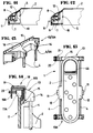
- the support shell 2 is slidably mounted on lateral slides 4 and furthermore comprises unlockable translation locking means 5, more particularly illustrated in FIGS. 11 and 12, having the function to immobilize said support shell 2 on said slides 4 while allowing, under the action of a manual control, its movement along the latter.
- the shell 2 of the hydrotherapy device can, as shown in FIG. 1, be placed at any location along these lateral slides 4 so as to allow the user to massage any part of the body.
- this support shell 2 comprises, in line with said operating handles 11, support flanges 12 allowing the user to simultaneously grasp said operating handles 11 and the support shell 2 in view adjust its position along the slides 4.
- such a fixing support 13, 13A comprises means 14 for receiving these ends 6, 6A of the slides 4, of tubular shape, as well as a fixing base 15.
- the latter is provided with openings 16 serving for the passage of fixing members, such as screws, when it is advisable to attach, directly, the hydrotherapy device 1 to any wall.
- this fixing base 15 can receive hooking means 18 and clamping means 20 allowing, ultimately, simply to hang the hydrotherapy device 1 on such a wall 17 of a cabin. shower.
- attachment means 18 are in the form of an inverted "U" piece 19 of which at least one of the vertical parallel walls 19A is made integral with the fixing base 15, while the other parallel wall vertical 19B receives the clamping means 20, such as a screw or the like. These are tightened on the upper section 17A of this wall 17 once the "U" piece 19 engaged on the latter.
- the fixing supports 13, 13A can be mounted or be an integral part of a single panel which can then receive, on one of its lateral edges such hinge fittings 22 authorizing the pivoting of the hydrotherapy device 1 around a vertical axis.
- this hydrotherapy device 1 is pivotable relative to the partition against which it is fixed may prove to be particularly advantageous in the context of an application of this device above a bathtub. More particularly, in this case, this hydrotherapy device 1 can, as the case may be, be folded down parallel to the partition against which it is fixed in order to make it less bulky or, on the contrary, in the event of use , brought perpendicular to this partition, for example in the longitudinal axis of the bathtub.
- these nozzles 3 are connected to a conduit 47 of a primary water supply network and deliver a water jet with a massaging effect.
- these nozzles 3 comprise means for transforming the flow of water from the primary network into an outlet pressure greater than that of the latter, when it is expelled into the open air.
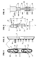
- the means for transforming the flow of water into pressure are constituted by a first chamber A for reducing the cross-section of the primary water supply duct of the nozzle 3 and a pressure chamber C succeeding it, of larger section and extending itself, by an expulsion chamber D whose section of dimension smaller than the pressure chamber C constitutes a second reduction.
- the pressure chamber C comprises means for giving the water flow a swirling spiral movement, these means 23 being constituted, essentially, by a helical groove 24, which can preferably be likened to a thread whose pitch of the propeller is very large and advantageously comprising an asymmetrical profile.
- an injection chamber B of section smaller than that of the first reduction A is interposed between the latter and the pressure chamber C to constitute a third reduction.
- the injection chamber B has a diameter corresponding to the diameter of the chamber A divided by two. While the pressure chamber C has a diameter corresponding to twice the diameter of the first chamber A, that is four times greater than the diameter of the injection chamber B. Finally, the expulsion chamber D has a diameter , corresponding, substantially, to that of the first intake chamber A.
- FIG. 5 In order to better understand the phenomenon applied in the context of the present invention, reference will be made, more particularly, to FIG. 5.
- this is divided into a rotating mass a and an accelerating mass b.
- the rotation of part of the flow generates a vacuum in the center of the pressure chamber C which allows the part of the flow b to evolve freely and to accelerate.
- air injection means operating, for example, by a venturi effect.
- a nozzle 3 consists of a tubular rear body 24 determining the different chambers A, B, C for transforming the flow of water into outlet pressure and a front part 25 intended to ensure the 'emission of at least one jet of pressurized water and constituting, substantially, the expulsion chamber D.
- the pressure chamber C of the nozzle 3 and the injection chamber B are arranged on the same axis X, X 'while the first intake chamber A is located on another axis Y, Y 'perpendicular to the first.
- this rear body 24 of the nozzle 3 comprises, at its front end and on its outer periphery, a recess 26 defining a nozzle 27 of smaller section intended to be inserted in an orifice 28 formed in the hull support 2.
- This endpiece 27 is, moreover, threaded on its outer periphery for the reception of a lock nut 29 allowing, ultimately, to fix the nozzle 3 on this support shell 2.
- the front part 25 of said nozzle 3 is constituted, substantially, by a tubular insert 30 whose internal diameter is defined so as to constitute, substantially, said expulsion chamber D.
- this insert 30 comprises a front flange 31 provided with at least one central perforation 32 intended for the passage of a jet of pressurized water.
- the front flange 31 of this insert 30 comprises, a central perforation 32 and one or more peripheral perforations 33. More particularly the central perforation 32, preferably of a larger diameter has for purpose of allowing the expulsion of the accelerated water flow b, while the peripheral perforations 33 allow the ejection of the rotating body of water a.
- this front part 25 of a nozzle 3 can receive an adjustment cap 34 capable of being screwed onto the threaded end piece 27 of the rear body 24 and offering the possibility of adjust the water jet (s) at the nozzle outlet.
- this adjustment cap 34 has, on its front face, perforations 35, 36 including a central 35 capable of being positioned in line with the central perforation 32 of the insert 30. Consequently, by screwing in fully, the adjustment cap 34 so that it comes into contact against the front flange 31 of the insert 30 while ensuring the offset of the peripheral perforations 32 of the latter relative to those 36 of said adjustment cap 34, one obtains a single central jet. Then by unscrewing, gradually, this adjustment cap 34, one obtains as many jets as perforations 35, 36 knowing that the more one moves away from the front flange 31, the more the jets are flared.
- the nozzle 3 corresponding to the embodiment illustrated in FIG. 8 differs, essentially, from that described above in that the rear body 24 consists of two parts 24A, 24B.
- the first defines, in a way, the pressure chamber C and is in the form of a socket screwed into the part 24B and comprising at its internal wall, the thread defining the means 23 to give the water flow a swirling spiral movement.
- this part 24A in the form of a socket comprises, also at the periphery, an annular flange 37 playing, in a way, the role of the lock nut 29 in the embodiment corresponding to FIG. 6.
- the part 24A in the form of a socket, is introduced into the orifice 28 formed in said support shell 2, then it is screwed into the part 24B of said rear body 24 until they are tightened on the wall of said support shell 2.
- the insert 30A which receives the front end of the rear body 24 is, in this case, in the form of a flange having, substantially distributed around its center 38, perforations 39, 39A of different diameter or perforation groups 39B to the right of which an opening 40 can be positioned arranged in an adjustment cap 34A pivotally mounted on the front part 25 of the nozzle 3.
- this adjustment cap 34A pivotally mounted on the front part 25 of the nozzle 3.
- the nozzles 3 are arranged on a secondary water supply network 41 according to a distribution such as to obtain a regulation of the flows as a function of the desired conditions and massage points of the body.
- the supply network 41 consists of two groups 42, 43 of nozzles in parallel 3.1 to 3.6 relative to a common supply point 44.
- Each of the groups 42, 43 being itself formed three nozzles 3.1 to 3.3 and 3.4 to 3.6 connected together, in series.
- the secondary water supply network 41 can constitute, in itself, the first reduction chamber A, this with respect to the primary supply network 47.
- connection of this secondary supply network 41 to the primary network 47 is obtained using flexible connection means.
- the secondary supply network 41 of the latter is connected by means of a hose to the shower outlet of the existing shower tap. .
- this avoids any delicate execution of plumbing.
- the nozzles or groups of nozzles 3 are connected to water supply means acting successively and / or gradually in a direction going from the bottom to the top for the massage zones located below the hips. and from top to bottom for areas above the hips to achieve a drainage effect.
- These drainage means are constituted, for example, by a multi-way valve driven in rotation, either by pressure hydraulic produced by the primary supply water flow 44, or by an appropriate electric motor.
- a nozzle 3 can be provided rotating and driven in rotation by hydraulic pressure this in order to produce a penetrating local massage.
- the hydrotherapy device in accordance with the invention while being remarkably effective, turns out to be easy to use and, more particularly, to be easily assembled so that one can envisage its installation in any type of shower cubicle or even above any bathtub.
Landscapes
- Health & Medical Sciences (AREA)
- Epidemiology (AREA)
- Pain & Pain Management (AREA)
- Physical Education & Sports Medicine (AREA)
- Rehabilitation Therapy (AREA)
- Life Sciences & Earth Sciences (AREA)
- Animal Behavior & Ethology (AREA)
- General Health & Medical Sciences (AREA)
- Public Health (AREA)
- Veterinary Medicine (AREA)
- Bathtubs, Showers, And Their Attachments (AREA)
- Massaging Devices (AREA)
Applications Claiming Priority (2)
| Application Number | Priority Date | Filing Date | Title |
|---|---|---|---|
| FR9506166A FR2734155B1 (fr) | 1995-05-19 | 1995-05-19 | Dispositif d'hydrotherapie notamment adaptable a une cabine de douche |
| FR9506166 | 1995-05-19 |
Publications (2)
| Publication Number | Publication Date |
|---|---|
| EP0743056A2 true EP0743056A2 (de) | 1996-11-20 |
| EP0743056A3 EP0743056A3 (de) | 1997-06-04 |
Family
ID=9479317
Family Applications (1)
| Application Number | Title | Priority Date | Filing Date |
|---|---|---|---|
| EP96440045A Withdrawn EP0743056A3 (de) | 1995-05-19 | 1996-05-17 | Hydrotherapiegerät zur Massage des menschlichen Körpers |
Country Status (2)
| Country | Link |
|---|---|
| EP (1) | EP0743056A3 (de) |
| FR (1) | FR2734155B1 (de) |
Cited By (7)
| Publication number | Priority date | Publication date | Assignee | Title |
|---|---|---|---|---|
| FR2800633A1 (fr) * | 1999-11-05 | 2001-05-11 | Aubert Alain | Dispositif pour charger en continu un fluide |
| FR2846551A1 (fr) | 2002-10-31 | 2004-05-07 | E S M P | Dispositif d'hydrotherapie destine au massage du corps humain |
| WO2008073062A1 (en) * | 2006-12-14 | 2008-06-19 | Zsolt Keresztes | Saving head for water tap or shower switchable between standard and economical mode |
| EP1716299A4 (de) * | 2004-01-16 | 2010-04-21 | Watkins Mfg Corp | Beleuchtete laminarströmungswasserfallvorrichtung für bad |
| WO2010111865A1 (zh) * | 2009-03-31 | 2010-10-07 | 深圳市轻松科技股份有限公司 | 按摩器及其插头和插座 |
| CN109288664A (zh) * | 2018-11-09 | 2019-02-01 | 天津魁都科技有限公司 | 患者康复用生物陶瓷活水超声波综合水疗仪 |
| CN116788458A (zh) * | 2023-05-23 | 2023-09-22 | 南京航空航天大学 | 一种基于空化水射流的船体清洗装置 |
Family Cites Families (14)
| Publication number | Priority date | Publication date | Assignee | Title |
|---|---|---|---|---|
| US2949240A (en) * | 1955-03-24 | 1960-08-16 | Duo Temp Mfg Corp | Therapeutic shower |
| FR1235458A (fr) * | 1959-05-27 | 1960-07-08 | Tête de pulvérisation | |
| US3890656A (en) * | 1973-08-27 | 1975-06-24 | Cleo L Mathis | Whirlpool jet for bathtubs |
| US4154402A (en) * | 1977-03-10 | 1979-05-15 | Fletcher Samuel L | Shower head |
| GB1602127A (en) * | 1977-05-17 | 1981-11-04 | Crosweller & Co Ltd W | Spray nozzle for shower apparatus |
| FR2452919A1 (fr) * | 1979-04-04 | 1980-10-31 | Vittel Eaux Min | Appareil d'hydrotherapie, en particulier pour le traitement des algies vertebrales |
| NL8300018A (nl) * | 1983-01-04 | 1984-08-01 | Wientjes Kunststoff | Hydropneumatisch massagebad met pulserende-circulatiewater-straalsysteem. |
| US4542853A (en) * | 1983-01-14 | 1985-09-24 | Diamond Harvey E | Fluid valve with directional outlet jet of continuously changing direction |
| DE3303925C2 (de) * | 1983-02-05 | 1985-03-07 | Heinz Georg Hünibach Thun Baus | Massageeinrichtung |
| EP0269698A4 (de) * | 1986-06-03 | 1989-09-26 | Jacob G Guerrero | Vorrichtung zur schnellwirkenden hydromassage des ganzen körpers. |
| CH671528A5 (de) * | 1987-04-02 | 1989-09-15 | Massimiliano Keiser | |
| FR2681244B3 (fr) * | 1991-09-18 | 1994-11-25 | Gianfranco Zino | Appareillage pour l'hydromassage vertical a fonctionnement automatique et controle electronique. |
| IT1263696B (it) * | 1993-09-27 | 1996-08-27 | Jacuzzi Europ | Vasca da bagno per idromassaggio, in particolare idromassaggio dorsale |
| US5356077A (en) * | 1994-01-10 | 1994-10-18 | Shames Sidney J | Pulsating shower head |
-
1995
- 1995-05-19 FR FR9506166A patent/FR2734155B1/fr not_active Expired - Fee Related
-
1996
- 1996-05-17 EP EP96440045A patent/EP0743056A3/de not_active Withdrawn
Cited By (7)
| Publication number | Priority date | Publication date | Assignee | Title |
|---|---|---|---|---|
| FR2800633A1 (fr) * | 1999-11-05 | 2001-05-11 | Aubert Alain | Dispositif pour charger en continu un fluide |
| FR2846551A1 (fr) | 2002-10-31 | 2004-05-07 | E S M P | Dispositif d'hydrotherapie destine au massage du corps humain |
| EP1716299A4 (de) * | 2004-01-16 | 2010-04-21 | Watkins Mfg Corp | Beleuchtete laminarströmungswasserfallvorrichtung für bad |
| WO2008073062A1 (en) * | 2006-12-14 | 2008-06-19 | Zsolt Keresztes | Saving head for water tap or shower switchable between standard and economical mode |
| WO2010111865A1 (zh) * | 2009-03-31 | 2010-10-07 | 深圳市轻松科技股份有限公司 | 按摩器及其插头和插座 |
| CN109288664A (zh) * | 2018-11-09 | 2019-02-01 | 天津魁都科技有限公司 | 患者康复用生物陶瓷活水超声波综合水疗仪 |
| CN116788458A (zh) * | 2023-05-23 | 2023-09-22 | 南京航空航天大学 | 一种基于空化水射流的船体清洗装置 |
Also Published As
| Publication number | Publication date |
|---|---|
| EP0743056A3 (de) | 1997-06-04 |
| FR2734155A1 (fr) | 1996-11-22 |
| FR2734155B1 (fr) | 1997-11-07 |
Similar Documents
| Publication | Publication Date | Title |
|---|---|---|
| EP0978269B1 (de) | Massagegerät für Anwendung auf der Haut | |
| FR2613903A1 (fr) | Arroseur a rideau d'eau oscillant | |
| FR3112701A1 (fr) | Dispositif de distribution d’eau pour une installation de douche, permettant d’obtenir un effet pluie | |
| FR2664811A1 (fr) | Dispositif pour massage capillaires. | |
| EP0743056A2 (de) | Hydrotherapiegerät zur Massage des menschlichen Körpers | |
| FR2684548A3 (fr) | Appareil de traitement, utilisable en particulier pour le traitement cosmetique du visage. | |
| FR2694490A3 (fr) | Appareil portable sans moteur pour le nettoyage de la bouche. | |
| FR2734156A1 (fr) | Dispositif d'hydrotherapie destine au massage du corps humain | |
| FR2724550A1 (fr) | Dispositif ergonomique de projection d'eau sous forme de jets, destine a se doucher, se laver ou se masser, tout ou partie du corps | |
| EP1009272A1 (de) | Bogenförmige hydromassagedusche mit konvergenten strahlen | |
| FR2658435A1 (fr) | Appareil de douche a plusieurs fonctions. | |
| CH666180A5 (en) | Back massager fixed on wall - comprises panel with massaging heads to conform to shape of back and equipped with fluid dispensing nozzles | |
| FR2764188A3 (fr) | Dispositif de douche de massage dorsal pour cabine de douche | |
| FR2863510A3 (fr) | Tete pour douche multifonction | |
| WO1999023975A1 (fr) | Brosse de nettoyage de dents amovible pour dispositif de pulverisation | |
| FR2773314A1 (fr) | Douchette adaptee a la toilette des bebes et des enfants | |
| KR0119350Y1 (ko) | 샤워기헤드 지지대 | |
| FR2709940A1 (fr) | Dispositif ergonomique de projection d'eau sous forme de jets, destiné à se doucher ou se faire masser tout ou partie du corps. | |
| WO2009068773A2 (fr) | Systeme de sechage corporel a air chaud. | |
| FR2788967A1 (fr) | Table de massage | |
| FR3067240A1 (fr) | Systeme de projection de jets d’eau pour le remplissage d’une baignoire et baignoire hydro-enveloppante associee. | |
| EP1313567A2 (de) | Hygienischer brausekopf mit lösbarem diffusor | |
| FR2599410A1 (fr) | Jeu d'elements pour constituer et installer une main-courante ou analogue | |
| WO2018115785A1 (fr) | Dispositif de drainage lymphatique avec element de reception en forme de pince | |
| FR2706292A1 (fr) | Appareil de massages et de traitements thérapeutiques et esthétiques. |
Legal Events
| Date | Code | Title | Description |
|---|---|---|---|
| PUAI | Public reference made under article 153(3) epc to a published international application that has entered the european phase |
Free format text: ORIGINAL CODE: 0009012 |
|
| AK | Designated contracting states |
Kind code of ref document: A2 Designated state(s): AT BE CH DE DK ES GB GR IE IT LI LU MC NL PT SE |
|
| AX | Request for extension of the european patent |
Free format text: AL PAYMENT 960522;LT PAYMENT 960522;LV PAYMENT 960522;SI PAYMENT 960522 |
|
| RAX | Requested extension states of the european patent have changed |
Free format text: AL PAYMENT 960522;LT PAYMENT 960522;LV PAYMENT 960522;SI PAYMENT 960522 |
|
| PUAL | Search report despatched |
Free format text: ORIGINAL CODE: 0009013 |
|
| AK | Designated contracting states |
Kind code of ref document: A3 Designated state(s): AT BE CH DE DK ES GB GR IE IT LI LU MC NL PT SE |
|
| AX | Request for extension of the european patent |
Free format text: AL PAYMENT 960522;LT PAYMENT 960522;LV PAYMENT 960522;SI PAYMENT 960522 |
|
| STAA | Information on the status of an ep patent application or granted ep patent |
Free format text: STATUS: THE APPLICATION IS DEEMED TO BE WITHDRAWN |
|
| 18D | Application deemed to be withdrawn |
Effective date: 19971205 |