EP0743100A1 - Canal d'évacuation pour un précipitateur humide - Google Patents
Canal d'évacuation pour un précipitateur humide Download PDFInfo
- Publication number
- EP0743100A1 EP0743100A1 EP96107635A EP96107635A EP0743100A1 EP 0743100 A1 EP0743100 A1 EP 0743100A1 EP 96107635 A EP96107635 A EP 96107635A EP 96107635 A EP96107635 A EP 96107635A EP 0743100 A1 EP0743100 A1 EP 0743100A1
- Authority
- EP
- European Patent Office
- Prior art keywords
- outlet channel
- wet separator
- separator according
- curvature
- spray booth
- Prior art date
- Legal status (The legal status is an assumption and is not a legal conclusion. Google has not performed a legal analysis and makes no representation as to the accuracy of the status listed.)
- Granted
Links
- 239000012716 precipitator Substances 0.000 title 1
- 239000007921 spray Substances 0.000 claims description 83
- 239000007788 liquid Substances 0.000 claims description 50
- 239000000203 mixture Substances 0.000 claims description 18
- 238000005406 washing Methods 0.000 claims description 18
- 238000004140 cleaning Methods 0.000 claims description 11
- 230000007704 transition Effects 0.000 claims description 10
- 239000003595 mist Substances 0.000 claims description 3
- 230000015572 biosynthetic process Effects 0.000 description 20
- 239000003973 paint Substances 0.000 description 19
- 239000003570 air Substances 0.000 description 18
- 239000006260 foam Substances 0.000 description 18
- XLYOFNOQVPJJNP-UHFFFAOYSA-N water Substances O XLYOFNOQVPJJNP-UHFFFAOYSA-N 0.000 description 16
- 239000007789 gas Substances 0.000 description 15
- 230000000694 effects Effects 0.000 description 14
- 230000009467 reduction Effects 0.000 description 11
- 238000000926 separation method Methods 0.000 description 10
- 238000005187 foaming Methods 0.000 description 9
- 239000000701 coagulant Substances 0.000 description 8
- 238000005507 spraying Methods 0.000 description 7
- 239000004922 lacquer Substances 0.000 description 6
- 230000004048 modification Effects 0.000 description 6
- 238000012986 modification Methods 0.000 description 6
- 210000001331 nose Anatomy 0.000 description 5
- 230000008901 benefit Effects 0.000 description 4
- 239000002184 metal Substances 0.000 description 4
- 230000001914 calming effect Effects 0.000 description 3
- 239000002245 particle Substances 0.000 description 3
- 238000004064 recycling Methods 0.000 description 3
- POAOYUHQDCAZBD-UHFFFAOYSA-N 2-butoxyethanol Chemical compound CCCCOCCO POAOYUHQDCAZBD-UHFFFAOYSA-N 0.000 description 2
- 239000000654 additive Substances 0.000 description 2
- 230000002411 adverse Effects 0.000 description 2
- 150000001412 amines Chemical class 0.000 description 2
- 230000008859 change Effects 0.000 description 2
- 238000005374 membrane filtration Methods 0.000 description 2
- 238000010079 rubber tapping Methods 0.000 description 2
- 239000002904 solvent Substances 0.000 description 2
- 238000007592 spray painting technique Methods 0.000 description 2
- 238000000108 ultra-filtration Methods 0.000 description 2
- 239000004924 water-based lacquer Substances 0.000 description 2
- 229910000831 Steel Inorganic materials 0.000 description 1
- 230000001133 acceleration Effects 0.000 description 1
- 230000009471 action Effects 0.000 description 1
- 239000000853 adhesive Substances 0.000 description 1
- 230000001070 adhesive effect Effects 0.000 description 1
- 239000012080 ambient air Substances 0.000 description 1
- 238000000889 atomisation Methods 0.000 description 1
- 238000005452 bending Methods 0.000 description 1
- 239000011248 coating agent Substances 0.000 description 1
- 238000000576 coating method Methods 0.000 description 1
- 238000011109 contamination Methods 0.000 description 1
- 230000008021 deposition Effects 0.000 description 1
- 239000006185 dispersion Substances 0.000 description 1
- 239000000945 filler Substances 0.000 description 1
- 239000012530 fluid Substances 0.000 description 1
- 230000006872 improvement Effects 0.000 description 1
- 239000000463 material Substances 0.000 description 1
- 238000001471 micro-filtration Methods 0.000 description 1
- 239000012466 permeate Substances 0.000 description 1
- 239000004033 plastic Substances 0.000 description 1
- 238000001223 reverse osmosis Methods 0.000 description 1
- 238000007789 sealing Methods 0.000 description 1
- 238000004062 sedimentation Methods 0.000 description 1
- 229910001220 stainless steel Inorganic materials 0.000 description 1
- 239000010935 stainless steel Substances 0.000 description 1
- 239000010959 steel Substances 0.000 description 1
Images

Classifications
-
- B—PERFORMING OPERATIONS; TRANSPORTING
- B05—SPRAYING OR ATOMISING IN GENERAL; APPLYING FLUENT MATERIALS TO SURFACES, IN GENERAL
- B05B—SPRAYING APPARATUS; ATOMISING APPARATUS; NOZZLES
- B05B14/00—Arrangements for collecting, re-using or eliminating excess spraying material
- B05B14/40—Arrangements for collecting, re-using or eliminating excess spraying material for use in spray booths
- B05B14/46—Arrangements for collecting, re-using or eliminating excess spraying material for use in spray booths by washing the air charged with excess material
-
- B—PERFORMING OPERATIONS; TRANSPORTING
- B05—SPRAYING OR ATOMISING IN GENERAL; APPLYING FLUENT MATERIALS TO SURFACES, IN GENERAL
- B05B—SPRAYING APPARATUS; ATOMISING APPARATUS; NOZZLES
- B05B14/00—Arrangements for collecting, re-using or eliminating excess spraying material
- B05B14/40—Arrangements for collecting, re-using or eliminating excess spraying material for use in spray booths
- B05B14/46—Arrangements for collecting, re-using or eliminating excess spraying material for use in spray booths by washing the air charged with excess material
- B05B14/468—Arrangements for collecting, re-using or eliminating excess spraying material for use in spray booths by washing the air charged with excess material with scrubbing means arranged below the booth floor
-
- Y—GENERAL TAGGING OF NEW TECHNOLOGICAL DEVELOPMENTS; GENERAL TAGGING OF CROSS-SECTIONAL TECHNOLOGIES SPANNING OVER SEVERAL SECTIONS OF THE IPC; TECHNICAL SUBJECTS COVERED BY FORMER USPC CROSS-REFERENCE ART COLLECTIONS [XRACs] AND DIGESTS
- Y02—TECHNOLOGIES OR APPLICATIONS FOR MITIGATION OR ADAPTATION AGAINST CLIMATE CHANGE
- Y02P—CLIMATE CHANGE MITIGATION TECHNOLOGIES IN THE PRODUCTION OR PROCESSING OF GOODS
- Y02P70/00—Climate change mitigation technologies in the production process for final industrial or consumer products
- Y02P70/10—Greenhouse gas [GHG] capture, material saving, heat recovery or other energy efficient measures, e.g. motor control, characterised by manufacturing processes, e.g. for rolling metal or metal working
Definitions
- the invention relates to a wet separator for a spray booth or a spray booth, with at least partially inclined inflow surfaces that converge towards a floor outlet and open into a curved outlet channel that is inclined relative to the vertical and that opens into an expansion chamber, at least one of the inflow surfaces via a bend passes into the outlet channel.
- Such a wet separator is known from DE 33 17 230 C2.
- the known arrangement comprises a spray booth with a wet separator with a floor outlet with outlet sides converging in the direction of flow, washing liquid being supplied to the floor outlet from lateral reservoirs or via inclined inflow surfaces.
- the bottom outlet has a neck in which the inflowing air and water flows mix and which is followed by a dispersion chamber which opens into a second outlet, which, like the first outlet, is designed as a venturi, with a significantly smaller clear width than this.
- the bottom outlet has speed-increasing and pre-separating functions, while the second outlet gives the passing mixture flow an even higher speed in order to separate it again and more intensely.
- the floor outlet has a guide surface in the direction of flow, which is essentially flat and forms a continuation of a straight outlet side of the floor outlet, after bending to a less steep course between 5 ° and 45 ° to the horizontal, the guide surface delimiting the neck on the lower side .
- the object of the invention is therefore to provide a wet separator for a spray booth or a spray booth, which can also be used for water-based paints without the addition of coagulant, without problems due to excessive foaming.
- the object of the invention is completely achieved in this way, since the two oppositely directed curvatures of the outlet channel, which in total form approximately the shape of an S, cause a strong calming and deceleration of the liquid / gas mixture flowing into the floor outlet.
- the flow rate is significantly reduced, and in conjunction with gentle curvatures at the transitions, the foam formation with water-based paint is greatly reduced.
- Effective separation is achieved through double flooding of the outlet channel from both inflow surfaces.
- There is no need to add coagulant which means that the washing liquid, ie the spray booth circulating water, has to be recycled considerably is facilitated.
- the recycling can be carried out by concentration using membrane filtration, for example by ultrafiltration, microfiltration or reverse osmosis.
- the outlet channel merges into an inclined floor surface of the expansion space, the inclination of which is at least approximately 10 ° with respect to the horizontal.
- the outlet channel gently merges into an inclined floor surface of the expansion space, the liquid flow is calmed further and foam formation is thereby reduced. Furthermore, as a result of the smooth transition from the outlet curvature to the bottom surface of the expansion space, a vertical impact of the liquid flow from the upper boundary of the outlet channel onto the underlying surface is avoided and instead a largely gentle, low-vortex flow is achieved.
- the inclination of the floor surface is between approximately 10 ° and 30 °, in particular between approximately 15 ° and 20 °.
- the opposite curvature of the outlet channel is curved more than 90 °.
- the oppositely directed curvature of the outlet channel is followed by a second, oppositely directed curvature, which merges into the bottom surface of the expansion space.
- This measure has the advantage that the additional, oppositely directed curvature further calms the liquid / gas mixture and thus further reduces foam formation.
- the upper boundary surface of the outlet channel is extended in the direction of the inflow surface lying above it, preferably up to the inflow surface lying above it.
- This configuration avoids a tear-off edge on the upper boundary surface of the outlet channel and improves the overall diffuser effect at the end of the outlet channel without swirling to a greater extent. This measure also contributes to a significant reduction in foam formation.
- the extension of the upper boundary surface improves the diffuser effect and makes it possible to install it to avoid cutting sheets, droplet separators or filters in the expansion room, since fewer droplets are carried away.
- the bottom surface of the expansion space merges into an outlet channel via a curvature of less than 90 °.
- the outlet channel has a slope directed transversely to the direction of flow of the liquid on the bottom surface.
- the inclinations of the inflow surfaces, their transitions to the outlet channel, and the shape of the outlet channel are coordinated with one another in such a way that the flow speed in the outlet channel is at most 15 m per second, preferably between approximately 6 and 10 m per second.
- spray or mist nozzles are provided at the end of the outlet channel in order to spray the liquid / gas mixture emerging from the outlet channel from above.
- tapping plates, droplet separators or filters are provided within the expansion space.
- washing nozzles are provided within the expansion space for cleaning the boundary surfaces.
- This measure makes it possible to remove deposits that have occurred within the expansion space from time to time or even to prevent deposits from occurring during the spraying operation. This can be particularly advantageous for paints and other paints that tend to form films and dry out even at room temperature.
- an access door can be provided within the expansion space.
- This measure has the advantage that within the expansion space, which is of sufficient size due to the sloping floor surface and its slope, also manual cleaning e.g. can be done with the help of a high-pressure cleaner, provided that thick deposits should have formed within the expansion space during operation.
- other cleaning devices or devices for cleaning the expansion space can also be introduced through such a door.
- the inflow surfaces of the wet separator are connected to the wall surfaces of the spray booth via curvatures, in the area of which washing nozzles are arranged.
- a projection is provided as a drip nose at least on the at least one curvature of the inflow surface or on the upper boundary surface of the outlet channel.
- the projections are sealingly connected to the curvature of the inflow surface or to the upper boundary surface of the outlet channel.
- approximately right-angled or also acute-angled angles can be provided, the leg length of which is preferably between approximately 10 and 20 mm.
- Such a design of the projections ensures, on the one hand, a sufficient effect for detachment or partial detachment of the liquid from the surface and, on the other hand, enables easy cleaning, since all surfaces on which paint residues can settle are easily accessible.
- a wet separator according to the invention can be used advantageously both for a spray booth and for a spray booth.
- a spray booth is a booth which is closed on all sides and in which air is guided from top to bottom.
- a spray booth is open on one side from which the operating personnel can work towards the rear wall of the spray booth, that is to say spray paint.
- the air flow in a spray booth naturally, unlike in a spray booth, does not run from top to bottom but from front to back.
- both inflow surfaces are inclined towards the side walls of the spray booth and go directly into the flooded side walls, preferably via curvatures, in the area of which additional washing nozzles are located.
- a wet separator according to the invention is used in a spray booth, the wet separator connects directly to the flooded rear wall, which then merges into the outlet channel of the wet separator via the at least one curvature, to which the oppositely directed curvature of the outlet channel connects.
- the exhaust air can be discharged from the expansion space of the wet separator into a scrubber, which is preferably coupled to a side wall of the spray stand.
- a scrubber which is preferably coupled to a side wall of the spray stand.
- a washer can be provided on both side walls.
- one or more washers are provided in the front area of the spray booth opposite the flooded rear wall.
- a spray booth according to the invention is generally designated by the number 10.
- the spray booth 10 comprises a spray chamber 12, on the bottom of which a wet separator for separating liquids and gases is provided, which is designated as a whole by the number 60 and which will be described in more detail below.
- Supply air is supplied to the spray chamber 12 from above via a filter 35, as is indicated schematically by the arrow 36.
- the spray booth air is discharged downward together with the liquid flow via the wet separator 60, passes through an expansion space 72 and, at the upper end of the expansion space 72, passes through an exhaust air duct 52 into a scrubber 26, in which the exhaust air is cleaned and filtered and then partly the spray chamber 12 again supplied laterally from above is, as indicated by arrow 38 and the other part is emitted to the ambient air with the help of appropriate fan support, as indicated by arrow 40.
- the walls of the spray booth 10 are designed as trickling surfaces 16, 18 which are sprinkled from small reservoirs 30, 34 which are supplied with spray booth circulating water via lines 28, 32.
- the spray booth shown is a larger system in which the exhaust air from the spray booth pre-cleaned in the wet separator 60 is carefully cleaned in the scrubber 26.
- the washer 26 shown is designed as a nozzle washer, which has a plurality of washing nozzles 50, which are supplied with rinsing liquid via a line 48. Furthermore, a plurality of filters are provided, which are indicated by the number 42 by way of example and which can additionally be cleaned by spray nozzles 46, to which washing liquid or permeate from an ultrafiltration is fed via a line 44.
- the washing liquid obtained in the scrubber 26 returns to a rinsing circuit via an outlet 54.
- the additional scrubber 26 can be dispensed with, in particular in the case of smaller systems, and that the exhaust air cleaned in the wet separator can be released directly to the environment via an exhaust air duct.
- a floor grate 20 is provided at the lower end above the wet separator 60, on which the operating personnel can stand. In the case of automatic cabins, such a floor grating is preferably completely dispensed with.
- the walls of the spray chamber 12 merge at the lower end via curvatures 55 into flat inflow surfaces 56, 58 which are inclined toward a floor outlet 62 arranged approximately in the middle of the spray chamber 12.
- the spray booth 10 according to the invention can in principle be used for spray painting with any paint materials, for example for conventional solvent-based paints, for water-soluble or non-water-soluble stoving paints, for solvent-based or water-soluble fillers or for numerous other paints.
- the spray booth 10 according to the invention has particular advantages, in particular when using water-soluble paint, so-called water paint, since water paint in the spray booth circulating water in conventional spray booths leads to extraordinarily strong foam formation, which represents a considerable problem when operating the spray booth.
- the wet separator 60 according to the invention is designed such that foaming is largely avoided even in the case of water-based paint, so that the spray booth 10 according to the invention can be used without foaming even with large amounts of circulating washing liquid.
- the addition of coagulant can be dispensed with, which enables recycling of the overspray that enters the spray booth circulation water with the aid of membrane filtration.
- the two inflow surfaces 56, 58 are inclined towards the center, in the direction of the bottom outlet 62 and merge into an outlet channel 64 via curves 66, 70, which opens into the expansion chamber 72.
- the inclination of the two inflow surfaces is approximately 15 ° to the horizontal.
- the inflow surface 56 on the left in FIG. 1 merges via the curvature 70, which covers approximately an angle of 30 °, into a lower section 57, which forms the start of the outlet channel 64.
- the opposite inflow surface 58 on the right-hand side merges into the upper surface of the outlet channel 64 via a gentle curvature 66 which covers an angle of approximately 120 °.
- the outlet channel 64 thus forms an angle of approximately 60 ° at its upper end with the inflow surface 58.
- the central axis 65 of the outlet channel 64 on the inlet side is inclined at an angle ⁇ of approximately 40 ° with respect to the vertical.
- the curvature 66 of the outlet channel 64 is followed by a second curvature 68 which is opposite to the first curvature 66 with which the inflow surface 58 merges into the outlet channel 64.
- the two curvatures 66, 68 arranged one behind the other thus form the shape of an S.
- the second curvature 68 covers an angle ⁇ of approximately 110 ° to 120 ° and merges into a flat bottom surface 74 of the expansion chamber 72.
- the flat bottom surface 74 of the expansion chamber 72 forms an angle ⁇ of approximately 15 ° to 20 °, preferably of approximately 15 °, with the horizontal.
- the lower section 57 of the inflow surface 56 which forms the inlet of the outlet channel 34, is followed by a curvature 59, which in turn has a flat surface at the end of the outlet channel 64 connects upper boundary surface 94, which is led back to the underside of lower section 57 of inflow surface 56.
- the lower section 57, the curvature 59 and the upper boundary surface 94 thus enclose an approximately teardrop-shaped cross section.
- the outlet channel 64 has an area of approximately uniform cross section in its upper section after the converging area, which area is maintained until the end of the curve 68.
- the outlet channel 64 only widens at its lower end through the continuation of the curvature 59 up to the flat upper boundary surface 94, so that the end of the outlet channel 64 is designed as a diffuser, which is indicated schematically by the number 96.
- a tube is arranged above the bottom surface 74 next to the upper boundary surface 94, on which a plurality of washing nozzles 92 are provided, which allow spraying of the bottom surface 74 underneath.
- the expansion space 72 has an approximately triangular cross section, is delimited on its upper side by the inflow surface 56 and the upper delimiting surface 94 of the outlet channel 64 and is closed at its end opposite the outlet channel 64 by a vertical end wall 51.
- Wash nozzles for cleaning are arranged both in front of the vertical end wall 51 and below the inflow surface 56, which are indicated schematically by the numbers 90 and 88, respectively.
- the expansion space 72 is accessible through a door 86 so that the surfaces can be cleaned manually using a high-pressure cleaner or the like. Other cleaning devices or devices can also be introduced through such a door 86.
- the bottom surface 74 of the expansion space 72 merges via a gentle curvature 76 into an outlet channel 78 which extends in the direction of the longitudinal extent of the spray booth 10, i.e. So perpendicular to the direction of flow of the liquid, is inclined on the bottom surface 74 with a slope.
- the outlet channel 78 finally ends in an outlet 80 which is connected via a line 82 to a downstream collecting container 84.
- the wall surfaces 16, 18 are sprinkled with washing liquid, as is indicated schematically by the liquid film in FIG. 1, the washing liquid is conducted into the outlet channel 64 via the bends 55 and the inflow surfaces 56, 58.
- the cabin air which flows vertically through the spray chamber 12 from top to bottom, enters the outlet channel 64 and mixes there with the liquid flow, as indicated by the arrows 98, 100, 102. Due to the double flooding of the outlet channel 64 from two sides, a good separation effect of the wet separator 60 is achieved on the one hand and excessive foam formation is prevented on the other hand.
- the special geometry of the outlet channel 64 and in particular its design as a diffuser 96 at the outlet end prevents foaming in the case of water-based lacquer without the need to add coagulants.
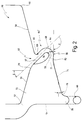
- FIG. 2 A section of an alternative embodiment of a wet separator according to the invention of a spray booth, which is designated overall by the number 110, is shown enlarged in FIG. 2.
- the wet separator 60 ' is slightly modified compared to the embodiment previously explained with reference to FIG. 1.
- the same reference numerals are used for corresponding parts as in Fig. 1.
- the wet separator 60 'differs from the embodiment previously explained with reference to FIG. 1 in that the second curvature 68 is followed by a further curvature 112, directed opposite the second curvature 68, at the end of the outlet channel 64, by means of which it gently penetrates the floor surface 74 passes.
- Another difference from the previously described Wet separator 60 consists in the fact that the curvature 59 of the upper boundary surface of the outlet channel 64 also continues in the expansion space 72 to the lower section 57 of the inflow surface 56, so that through the lower section 57 of the inflow surface 56 and through the adjoining curvature 59 an overall approximately wing-shaped cross section with flow line shape is formed.
- outlet channel 64 which widens outward on both sides in its diffuser region 96 through the curvatures 112 and 94, enables an even better overall reduction in the flow rate of the liquid / gas mixture in the diffuser 96 without vortex formation, thereby reducing the risk of Foaming with water-based paint is reduced even further.
- the angle ⁇ , through which the curvature 112 is angled down to the bottom surface 74, is preferably in a range from approximately 10 ° to 30 °.
- the angle ⁇ which the second curvature 68 traverses is preferably somewhat larger than in the embodiment according to FIG. 1 and is in a range from approximately 130 ° to 150 °.
- a further difference of the wet separator 60 'compared to the wet separator 60 described above with reference to FIG. 1 is that on the curvature 66 of the inflow surface 58 at the beginning of the outlet channel 64 and on the curvature 59 at the end of the outlet channel 64 there is a downward projection 69 or 71 is designed as a drip nose.
- the projections 69, 71 are designed as isosceles angles at 90 ° with a leg length of about 10 to 20 mm, which are directly connected to the curves 66 and 59, for example, sealingly. are welded on and extend substantially over the entire width of the outlet channel 64.
- These downward-pointing projections 69 and 71 support detachment or partial detachment of the liquid sucked down through the outlet channel from the surfaces. If, in addition to water, the liquid contains certain additives such as butyglycol or amines or has already absorbed certain amounts of lacquer, the liquid largely adheres to the surfaces due to the higher adhesive tension.
- the projections 69 and 71 achieve a certain detachment of the liquid from the surfaces and thus improve the separation effect. Nevertheless, the geometry of the wet separator is not adversely affected, so that no increased foaming occurs.
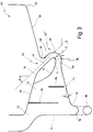
- a further modification of the spray booth according to the invention is shown in the area of the wet separator in FIG. 3 and is designated overall by the number 120.
- the wet separator which is designated by the number 60 ′′, corresponds essentially to the embodiment according to FIG. 2, with only the upper boundary surface 94 being designed as a curvature even further into the expansion space 72 up to the inflow surface 56.
- the cross section of the outlet channel 64 therefore increases less rapidly with increasing distance in the diffuser area 96 from the curvature 68 than is the case in the embodiment according to FIG. 2.
- the projections 69, 71 are designed as a downward-facing sheet metal strip in a modification of the embodiment according to FIG. 2.
- vertical tapping plates 114, 116 are provided in the expansion space 72, by means of which the separation effect is improved.
- droplet separators filters or similar devices can also be provided instead.
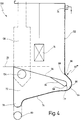
- FIG. 4 shows a further modification of a wet separator according to the invention using the example of a spray booth, which is designated overall by the number 130.
- the wet separator 60 ''' is connected to the rear flooded rear wall 132 of the spray booth 130.
- the rear wall 132 flooded from a reservoir merges directly into the outlet channel 64 of the wet separator 60 ′′ ′′ via the curvature.
- the curvature 66 is in turn followed by the reverse curvature 68, which at the end of the outlet channel 64 merges directly into the bottom surface 74 of the expansion space 72 via a gentle curvature.
- the opposite side of the outlet channel 64 is formed by the inclined inflow surface 56, which at the entrance of the outlet channel 64 merges into the curvature 59, which at the end of the outlet channel merges into the upper boundary surface 94, which in turn is sealingly connected to the underside of the inflow surface 56.
- a downward projection 69 or 71 is in shape both at the lower end of the flooded rear wall 132, that is to say at the curve 66, and at the curve 59 at the end of the outlet channel 64 an angle is provided, which extends practically over the entire width of the outlet channel 64 and is welded to the curvature 66 or 59 in question.
- the wet separator 60 ′′ ′′ according to the invention achieves an extraordinarily good separation effect, which is additionally reinforced by the projections 69 and 71, at the same time largely preventing foam formation even with water-soluble lacquer.
- the spray booth 130 has a floor grate 20 which is intended as a standing surface for an operator in order to be able to treat workpieces 14, for example by spray painting.
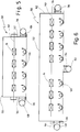
- the exhaust air from the expansion chamber 72 is guided into two washers, only one of which is shown in dashed lines in FIG. 4 and designated by the number 136, which is flanged to the side via a channel 134, as is shown in more detail in the illustration according to FIG. 5 is seen.
- a washer 136 or 138 is flanged to each side wall 142, 144 according to FIG. 5 via a channel 134 or 135.
- This lateral arrangement of the washers 136 and 138 does not affect the working space within the spraying station 130, so that workpieces 14, which are moved through the spraying station 130 by a conveyor 140, for example, are handled unhindered by operators 146, e.g. can be spray painted.
- FIG. 6 A further modification of a spray booth according to the invention is shown in FIG. 6 and is designated overall by the number 150.
- This embodiment differs from the embodiment previously described with reference to FIG. 5 only in that the spray booth 150 is considerably longer than the spray booth 130 according to FIG. 5, so that the two washers 136 and 138 arranged on the side no longer ensure adequate exhaust air treatment.
- a further washer 152 is additionally arranged approximately in the middle of the longitudinal extent on the front of the spray booth 150, that is to say opposite the rear wall 132, which is flanged to the expansion space 72 via a channel 154 running transversely to the direction of movement of the conveyor 140.
- the working area of the spray booth 150 is locally restricted by this washer 152, but spray booths of any length can be constructed in this way.
- sheet metal includes a version that is finely edged on many segments, since sheet metal is difficult to bend over a large area.
- the wet separator is usually made of sheet metal, preferably stainless steel sheet, but a version made of plastic or sheet steel with a non-stick coating is also conceivable.
Landscapes
- Details Or Accessories Of Spraying Plant Or Apparatus (AREA)
- Lubrication Details And Ventilation Of Internal Combustion Engines (AREA)
- Separation Using Semi-Permeable Membranes (AREA)
- Separating Particles In Gases By Inertia (AREA)
Applications Claiming Priority (4)
| Application Number | Priority Date | Filing Date | Title |
|---|---|---|---|
| DE19518172A DE19518172A1 (de) | 1995-05-19 | 1995-05-19 | Spritzkabine |
| DE19518172 | 1995-05-19 | ||
| DE19612813 | 1996-03-30 | ||
| DE19612813A DE19612813A1 (de) | 1995-05-19 | 1996-03-30 | Naßabscheider |
Publications (2)
| Publication Number | Publication Date |
|---|---|
| EP0743100A1 true EP0743100A1 (fr) | 1996-11-20 |
| EP0743100B1 EP0743100B1 (fr) | 2002-11-06 |
Family
ID=26015237
Family Applications (1)
| Application Number | Title | Priority Date | Filing Date |
|---|---|---|---|
| EP96107635A Expired - Lifetime EP0743100B1 (fr) | 1995-05-19 | 1996-05-14 | Canal d'évacuation pour un précipitateur humide |
Country Status (2)
| Country | Link |
|---|---|
| EP (1) | EP0743100B1 (fr) |
| AT (1) | ATE227166T1 (fr) |
Cited By (1)
| Publication number | Priority date | Publication date | Assignee | Title |
|---|---|---|---|---|
| DE10329300A1 (de) * | 2003-06-30 | 2005-01-20 | Volkswagen Ag | Verfahren zur Auswaschung und Behandlung von Lacküberschüssen |
Citations (5)
| Publication number | Priority date | Publication date | Assignee | Title |
|---|---|---|---|---|
| US2906511A (en) * | 1956-05-01 | 1959-09-29 | Ajem Lab Inc | Gas washing apparatus |
| US4515073A (en) * | 1982-07-19 | 1985-05-07 | Alpha-Debon Industries, Inc. | Air scrubbing system |
| US4608064A (en) * | 1985-01-03 | 1986-08-26 | Protectaire Systems Co. | Multi-wash spray booth and method of capturing air borne particles |
| US4952221A (en) * | 1988-04-21 | 1990-08-28 | Taikisha Ltd. | Gas cleaning apparatus containing a centrifugal type paint mist separator |
| WO1991014509A1 (fr) * | 1990-03-19 | 1991-10-03 | Eric Von Gertten Ab | Dispositif servant a peindre au pistolet des objets ou a traiter ceux-ci de maniere semblable |
-
1996
- 1996-05-14 EP EP96107635A patent/EP0743100B1/fr not_active Expired - Lifetime
- 1996-05-14 AT AT96107635T patent/ATE227166T1/de not_active IP Right Cessation
Patent Citations (5)
| Publication number | Priority date | Publication date | Assignee | Title |
|---|---|---|---|---|
| US2906511A (en) * | 1956-05-01 | 1959-09-29 | Ajem Lab Inc | Gas washing apparatus |
| US4515073A (en) * | 1982-07-19 | 1985-05-07 | Alpha-Debon Industries, Inc. | Air scrubbing system |
| US4608064A (en) * | 1985-01-03 | 1986-08-26 | Protectaire Systems Co. | Multi-wash spray booth and method of capturing air borne particles |
| US4952221A (en) * | 1988-04-21 | 1990-08-28 | Taikisha Ltd. | Gas cleaning apparatus containing a centrifugal type paint mist separator |
| WO1991014509A1 (fr) * | 1990-03-19 | 1991-10-03 | Eric Von Gertten Ab | Dispositif servant a peindre au pistolet des objets ou a traiter ceux-ci de maniere semblable |
Cited By (1)
| Publication number | Priority date | Publication date | Assignee | Title |
|---|---|---|---|---|
| DE10329300A1 (de) * | 2003-06-30 | 2005-01-20 | Volkswagen Ag | Verfahren zur Auswaschung und Behandlung von Lacküberschüssen |
Also Published As
| Publication number | Publication date |
|---|---|
| ATE227166T1 (de) | 2002-11-15 |
| EP0743100B1 (fr) | 2002-11-06 |
Similar Documents
| Publication | Publication Date | Title |
|---|---|---|
| DE2814276C2 (de) | Verfahren und Vorrichtung zum Reinigen der Abluft von Spritzkabinen | |
| DE3332457C2 (de) | Verfahren zur Rückgewinnung von Lackiermaterial aus dem beim Spritzlackieren entstehenden Overspray und Anordnung zur Durchführung des Verfahrens | |
| DE69919667T2 (de) | Nassabscheider und farbsprühkabine mit diesem nassabscheider | |
| DE2552326A1 (de) | Spritzkabine | |
| DE3042464C2 (de) | Wäscher | |
| DE2851176C2 (fr) | ||
| DE3317230A1 (de) | Nassabscheider und verfahren zum reinigen von verunreinigter konditionierluft | |
| DE2161198C3 (de) | Vorrichtung zur Reinigung der Abluft einer Spritzkabine | |
| DE19612813A1 (de) | Naßabscheider | |
| DE1287042B (de) | Gaswaescher | |
| DE3427766A1 (de) | Vorrichtung zum einfetten von blechbaendern | |
| EP0743100B1 (fr) | Canal d'évacuation pour un précipitateur humide | |
| DE3408474C2 (fr) | ||
| EP0958977B1 (fr) | Installation de nettoyage pour carosserie de véhicules | |
| DE2857092A1 (en) | Paint spray booth with water wash | |
| EP0635317B1 (fr) | Appareil de nettoyage et/ou de traitement thermique de pièces, en particulier de bandes profilées | |
| DE19518172A1 (de) | Spritzkabine | |
| DE4431893C3 (de) | Naßabscheider | |
| EP0523415A2 (fr) | Procédé de séparation et de récupération pour peintures diluables à l'eau dans les cabines de pulvérisation ainsi que le système d'installation pour la mise en oeuvre du procédé | |
| DE4234527A1 (de) | Verfahren und Anordnung zum Rückführen von Lackiermaterial | |
| DE3715263C2 (fr) | ||
| DE4303752A1 (de) | Lackiereinrichtung | |
| DE3705746A1 (de) | Farbspritzstand mit kontinuierlicher auswaschung der lackpartikelchen und lackschlammabscheidung | |
| EP0529151B1 (fr) | Bac de récupération d'eau pour cabine de pulvérisation | |
| DE3151665C2 (de) | Auswaschvorrichtung, insbesondere für die Abluft von Lackspritzkabinen |
Legal Events
| Date | Code | Title | Description |
|---|---|---|---|
| PUAI | Public reference made under article 153(3) epc to a published international application that has entered the european phase |
Free format text: ORIGINAL CODE: 0009012 |
|
| AK | Designated contracting states |
Kind code of ref document: A1 Designated state(s): AT BE DE ES FR GB IT NL SE |
|
| 17P | Request for examination filed |
Effective date: 19961123 |
|
| 17Q | First examination report despatched |
Effective date: 20001019 |
|
| GRAG | Despatch of communication of intention to grant |
Free format text: ORIGINAL CODE: EPIDOS AGRA |
|
| GRAG | Despatch of communication of intention to grant |
Free format text: ORIGINAL CODE: EPIDOS AGRA |
|
| GRAH | Despatch of communication of intention to grant a patent |
Free format text: ORIGINAL CODE: EPIDOS IGRA |
|
| GRAH | Despatch of communication of intention to grant a patent |
Free format text: ORIGINAL CODE: EPIDOS IGRA |
|
| GRAA | (expected) grant |
Free format text: ORIGINAL CODE: 0009210 |
|
| AK | Designated contracting states |
Kind code of ref document: B1 Designated state(s): AT BE DE ES FR GB IT NL SE |
|
| PG25 | Lapsed in a contracting state [announced via postgrant information from national office to epo] |
Ref country code: GB Free format text: LAPSE BECAUSE OF FAILURE TO SUBMIT A TRANSLATION OF THE DESCRIPTION OR TO PAY THE FEE WITHIN THE PRESCRIBED TIME-LIMIT Effective date: 20021106 Ref country code: FR Free format text: LAPSE BECAUSE OF FAILURE TO SUBMIT A TRANSLATION OF THE DESCRIPTION OR TO PAY THE FEE WITHIN THE PRESCRIBED TIME-LIMIT Effective date: 20021106 |
|
| REF | Corresponds to: |
Ref document number: 227166 Country of ref document: AT Date of ref document: 20021115 Kind code of ref document: T |
|
| REG | Reference to a national code |
Ref country code: GB Ref legal event code: FG4D Free format text: NOT ENGLISH |
|
| REF | Corresponds to: |
Ref document number: 59609844 Country of ref document: DE Date of ref document: 20021212 |
|
| PG25 | Lapsed in a contracting state [announced via postgrant information from national office to epo] |
Ref country code: SE Free format text: LAPSE BECAUSE OF FAILURE TO SUBMIT A TRANSLATION OF THE DESCRIPTION OR TO PAY THE FEE WITHIN THE PRESCRIBED TIME-LIMIT Effective date: 20030206 |
|
| GBV | Gb: ep patent (uk) treated as always having been void in accordance with gb section 77(7)/1977 [no translation filed] |
Effective date: 20021106 |
|
| PG25 | Lapsed in a contracting state [announced via postgrant information from national office to epo] |
Ref country code: ES Free format text: LAPSE BECAUSE OF FAILURE TO SUBMIT A TRANSLATION OF THE DESCRIPTION OR TO PAY THE FEE WITHIN THE PRESCRIBED TIME-LIMIT Effective date: 20030529 |
|
| PG25 | Lapsed in a contracting state [announced via postgrant information from national office to epo] |
Ref country code: BE Free format text: LAPSE BECAUSE OF NON-PAYMENT OF DUE FEES Effective date: 20030531 |
|
| EN | Fr: translation not filed | ||
| PLBE | No opposition filed within time limit |
Free format text: ORIGINAL CODE: 0009261 |
|
| STAA | Information on the status of an ep patent application or granted ep patent |
Free format text: STATUS: NO OPPOSITION FILED WITHIN TIME LIMIT |
|
| 26N | No opposition filed |
Effective date: 20030807 |
|
| BERE | Be: lapsed |
Owner name: *WURSTER GERD Effective date: 20030531 |
|
| PG25 | Lapsed in a contracting state [announced via postgrant information from national office to epo] |
Ref country code: NL Free format text: LAPSE BECAUSE OF NON-PAYMENT OF DUE FEES Effective date: 20031201 |
|
| NLV4 | Nl: lapsed or anulled due to non-payment of the annual fee |
Effective date: 20031201 |
|
| PG25 | Lapsed in a contracting state [announced via postgrant information from national office to epo] |
Ref country code: IT Free format text: LAPSE BECAUSE OF NON-PAYMENT OF DUE FEES;WARNING: LAPSES OF ITALIAN PATENTS WITH EFFECTIVE DATE BEFORE 2007 MAY HAVE OCCURRED AT ANY TIME BEFORE 2007. THE CORRECT EFFECTIVE DATE MAY BE DIFFERENT FROM THE ONE RECORDED. Effective date: 20050514 |
|
| PGFP | Annual fee paid to national office [announced via postgrant information from national office to epo] |
Ref country code: AT Payment date: 20050530 Year of fee payment: 10 |
|
| PGFP | Annual fee paid to national office [announced via postgrant information from national office to epo] |
Ref country code: DE Payment date: 20050628 Year of fee payment: 10 |
|
| PG25 | Lapsed in a contracting state [announced via postgrant information from national office to epo] |
Ref country code: AT Free format text: LAPSE BECAUSE OF NON-PAYMENT OF DUE FEES Effective date: 20060514 |
|
| PG25 | Lapsed in a contracting state [announced via postgrant information from national office to epo] |
Ref country code: DE Free format text: LAPSE BECAUSE OF NON-PAYMENT OF DUE FEES Effective date: 20061201 |