EP0743203A1 - Dispositif adaptateur - Google Patents
Dispositif adaptateur Download PDFInfo
- Publication number
- EP0743203A1 EP0743203A1 EP96107653A EP96107653A EP0743203A1 EP 0743203 A1 EP0743203 A1 EP 0743203A1 EP 96107653 A EP96107653 A EP 96107653A EP 96107653 A EP96107653 A EP 96107653A EP 0743203 A1 EP0743203 A1 EP 0743203A1
- Authority
- EP
- European Patent Office
- Prior art keywords
- adapter device
- housing
- sleeve
- adapter
- sealing element
- Prior art date
- Legal status (The legal status is an assumption and is not a legal conclusion. Google has not performed a legal analysis and makes no representation as to the accuracy of the status listed.)
- Granted
Links
- 238000007789 sealing Methods 0.000 claims abstract description 55
- 230000008719 thickening Effects 0.000 claims description 3
- 230000037431 insertion Effects 0.000 abstract 1
- 238000003780 insertion Methods 0.000 abstract 1
- 238000005553 drilling Methods 0.000 description 10
- 241000209035 Ilex Species 0.000 description 2
- 238000011109 contamination Methods 0.000 description 2
- 230000005484 gravity Effects 0.000 description 2
- 230000002950 deficient Effects 0.000 description 1
- 239000013013 elastic material Substances 0.000 description 1
- 210000003746 feather Anatomy 0.000 description 1
- 238000002372 labelling Methods 0.000 description 1
- 238000005259 measurement Methods 0.000 description 1
- 239000002245 particle Substances 0.000 description 1
- 230000035515 penetration Effects 0.000 description 1
- 239000000725 suspension Substances 0.000 description 1
- 230000007704 transition Effects 0.000 description 1
Images





Classifications
-
- F—MECHANICAL ENGINEERING; LIGHTING; HEATING; WEAPONS; BLASTING
- F04—POSITIVE - DISPLACEMENT MACHINES FOR LIQUIDS; PUMPS FOR LIQUIDS OR ELASTIC FLUIDS
- F04B—POSITIVE-DISPLACEMENT MACHINES FOR LIQUIDS; PUMPS
- F04B33/00—Pumps actuated by muscle power, e.g. for inflating
- F04B33/005—Pumps actuated by muscle power, e.g. for inflating specially adapted for inflating tyres of non-motorised vehicles, e.g. cycles, tricycles
-
- B—PERFORMING OPERATIONS; TRANSPORTING
- B60—VEHICLES IN GENERAL
- B60C—VEHICLE TYRES; TYRE INFLATION; TYRE CHANGING; CONNECTING VALVES TO INFLATABLE ELASTIC BODIES IN GENERAL; DEVICES OR ARRANGEMENTS RELATED TO TYRES
- B60C29/00—Arrangements of tyre-inflating valves to tyres or rims; Accessories for tyre-inflating valves, not otherwise provided for
- B60C29/06—Accessories for tyre-inflating valves, e.g. housings, guards, covers for valve caps, locks, not otherwise provided for
- B60C29/064—Hose connections for pneumatic tyres, e.g. to spare wheels
-
- Y—GENERAL TAGGING OF NEW TECHNOLOGICAL DEVELOPMENTS; GENERAL TAGGING OF CROSS-SECTIONAL TECHNOLOGIES SPANNING OVER SEVERAL SECTIONS OF THE IPC; TECHNICAL SUBJECTS COVERED BY FORMER USPC CROSS-REFERENCE ART COLLECTIONS [XRACs] AND DIGESTS
- Y10—TECHNICAL SUBJECTS COVERED BY FORMER USPC
- Y10T—TECHNICAL SUBJECTS COVERED BY FORMER US CLASSIFICATION
- Y10T137/00—Fluid handling
- Y10T137/3584—Inflatable article [e.g., tire filling chuck and/or stem]
-
- Y—GENERAL TAGGING OF NEW TECHNOLOGICAL DEVELOPMENTS; GENERAL TAGGING OF CROSS-SECTIONAL TECHNOLOGIES SPANNING OVER SEVERAL SECTIONS OF THE IPC; TECHNICAL SUBJECTS COVERED BY FORMER USPC CROSS-REFERENCE ART COLLECTIONS [XRACs] AND DIGESTS
- Y10—TECHNICAL SUBJECTS COVERED BY FORMER USPC
- Y10T—TECHNICAL SUBJECTS COVERED BY FORMER US CLASSIFICATION
- Y10T137/00—Fluid handling
- Y10T137/8593—Systems
- Y10T137/85978—With pump
-
- Y—GENERAL TAGGING OF NEW TECHNOLOGICAL DEVELOPMENTS; GENERAL TAGGING OF CROSS-SECTIONAL TECHNOLOGIES SPANNING OVER SEVERAL SECTIONS OF THE IPC; TECHNICAL SUBJECTS COVERED BY FORMER USPC CROSS-REFERENCE ART COLLECTIONS [XRACs] AND DIGESTS
- Y10—TECHNICAL SUBJECTS COVERED BY FORMER USPC
- Y10T—TECHNICAL SUBJECTS COVERED BY FORMER US CLASSIFICATION
- Y10T137/00—Fluid handling
- Y10T137/8593—Systems
- Y10T137/877—With flow control means for branched passages
- Y10T137/87788—With valve or movable deflector at junction
- Y10T137/8782—Rotary valve or deflector
Definitions
- the invention relates to an adapter device, in particular for connecting a pump system with different valve connections, to a housing which has an inlet opening for the medium to be pumped and a plurality of outlet openings, the outlet openings being selectively and individually connectable to the inlet opening and by a sealing element opposite the inlet opening are sealed.
- the best-known pump system is, for example, an air pump for inflating air cushions, inflatable boats, bicycle or car tires, which can be a manual or motor-driven air pump.
- the aforementioned compressed air systems have a different valve connection, for example a Schrader valve is used for car tires and a Sclaverand valve for bicycles. Due to the different designs of the valves, it is not possible to apply compressed air to them via a single compressed air connection. Rather, a corresponding pump system with the corresponding valve connection is necessary for each special valve type.
- a combined wheel and car tire air pump which has two connection options. At the head end of the air pump there are two diametrically opposite connections, one for a Schrader valve and one for a Sclaverand valve.
- the connection that is not required is sealed with a ball seal.
- the ball is located in a bore which is arranged transversely to the longitudinal axis of the pump and has one of the two connections at its respective end. Due to gravity, the ball falls on the sealing lip below and is pressed by the air pressure.
- the function of the air pump is only guaranteed if the bore of the ball is approximately vertically aligned. If the hole is arranged horizontally, i.e.
- the position of the ball is not precisely defined or is not moved into a sealing position by gravity, so that there is no pressure on a seal and therefore no sealing of the second outlet opening.
- the object of the invention is therefore to create an adapter device which enables the use of as many valve connections as possible on a single pump system and avoids the aforementioned disadvantages.
- the sealing element is rotatably and / or slidably mounted within the housing and is movable by an outer annular sleeve which at least partially surrounds the housing.
- sealing element which is mounted so that it can be rotated and / or moved, it is possible to arrange several connections distributed over the circumference of the housing. Due to the rotatability of the sealing element, the valve connections that are not required can be sealed and a specific valve connection can be selected and connected to the pump system. Due to the sliding mobility, there is also the possibility of providing further valve connections in a second or even third level.
- the sealing element mounted within the housing is expediently displaced or rotated by an annular sleeve which at least partially surrounds the housing in order to ensure a secure hold and to enable an additional seal. Another advantage of this adapter device is that the functionality of the pump system is ensured in any position and that the large number of connection options results in a not inconsiderable cost saving because only a single pump system is required for the various compressed air systems.
- the housing is open at one end and the sleeve can be pushed onto the end of the housing and closes it.
- the sleeve forms the head end of the housing of the adapter device or the pump unit and, moreover, enables quick and easy assembly.
- the outlet opening is circumferentially distributed and / or arranged in the longitudinal direction of the housing, as a result of which the number of outlet openings or connection options can be expanded as desired.
- the sleeve is arranged coaxially to the housing above the individual outlet openings and, through an opening, releases a maximum of one of the outlet openings or closes all of them.
- the sleeve is arranged coaxially to the housing above the individual outlet openings and, through an opening, releases a maximum of one of the outlet openings or closes all of them.
- the tightness and stability of the pump system is increased by the coaxially arranged sleeve.
- the sealing element is ring-shaped and has a segment cutout which extends in the axial direction over a partial region of the sealing element and has an inner connecting channel to the inlet opening of the housing.
- the segment cutout only connects the outlet opening to the pump unit, which lies directly above the segment cutout, while the other outlet openings are closed at the same time by the sealing element.
- the sealing element In order to connect the sealing element to the outer sleeve or to ensure that the sealing element can be carried in rotation and / or sliding, it is provided that the sealing element is at least partially double-walled and forms a pocket into which a segmented ring shoulder of the sleeve engages for driving.
- the sleeve or the housing has a threaded or plug connection in the end face with an inwardly directed connecting channel which can be closed by a seal.
- the threaded or plug connection in the end face enables the arrangement of a further outlet opening or connection option to the adapter device.
- a hose connection with a corresponding threaded or plug connection can be screwed or pressed into the end face, so that the pump system can be equipped with further valve connections, which are located at the second end of the hose.
- the sleeve closes all other annularly arranged outlet openings and that the sealing of the connection bore in the end face is opened at the same time by the inserted threaded or plug-in connection.
- the sealing element has an annular collar at one end and a recessed and partially annularly pierced end face, on which An elastic thickening for sealing the connection bore is arranged on the end face. Through the introduced thread or This elastic thickening is pushed inwards so that a connection to the pump system is established.
- the housing and the sleeve is equipped with a catch made of a tongue and groove combination, which always comes into engagement when the breakthrough Sleeve releases an outlet opening.
- the outlet openings of the housing consist of a connecting channel and a round or square recess, which are provided for receiving a seal adapted to the respective sealing system.
- a push button is used to lock the sleeve in a locking position instead of an outlet opening.
- the housing has at least one axial longitudinal groove and / or an annular groove for guidance, in which at least one shoulder of the sleeve engages and is guided.
- the use of an annular groove in the housing ensures the rotatability of the sleeve, while the ability to move is provided by an axial longitudinal groove.
- a combination of an axial and an annular guide groove enables the sleeve to be pulled off in a certain rotational position, which is given, for example, by the position of the locking push button.
- the threaded or plug connection is provided for receiving a hose connection or a pressure gauge.
- the connection of, for example, a fixed pressure gauge to the adapter device enables the measurement of the air pressure of a compressed air system which is connected to the pump system via one of the other outlet openings.
- one of the recesses is provided for receiving an adapter, for example a ball or hose adapter, which, with a plug-in connection or a plurality of fastening lugs, snaps into an annular groove in the recesses for fastening and by means of an O-ring opposite the Housing is sealed.
- an adapter for example a ball or hose adapter, which, with a plug-in connection or a plurality of fastening lugs, snaps into an annular groove in the recesses for fastening and by means of an O-ring opposite the Housing is sealed.
- hose adapter has a double valve connection at the other end of the hose, which is connected by a rotatable control switch with a sealing element is connected in a rotationally fixed manner and seals or opens the valve connections individually, the control switch being arranged to be rotatable from the outside.
- control switch has a rotary head on the outside and a cylindrical partial segment with a rear end face on the inside, the cylindrical partial segment extending over a three-quarter circle and receiving an inwardly projecting pin of the hose connection, so that the control switch is secured against falling out is, wherein the control switch has a middle position in which both valve connections are closed and has two further positions in which one of the two valve connections is connected to the hose via a connecting channel.
- valve connections are rotatably mounted and secured by a fastening means which engages in a groove in the valve connections.
- a special application of the hose adapter with double valve connection applies to the regulation of oil / air suspension systems, which must not experience any pressure losses when adjusting and removing the valve connection. This possibility is given by the middle position of the control switch with a closing of the connecting channel to the valve connections.
- FIG. 1 shows a sectional side view and a section II of an adapter device 1 which is integrally formed on a pump system 2.
- the annular outer sleeve 3 is shown only schematically.
- the housing 4 of the adapter device 1 is formed onto the annular outer sleeve 3, which essentially consists of an annular extension and has a plurality of bores or openings.
- a central and axially arranged bore 5 is connected to the pump chamber 6 of the pump system 2.
- a total of four recesses 7 are incorporated, which are each offset by 90 ° to one another. However, it is conceivable that a larger number of recesses 7 are distributed over the circumference of the housing 4.
- the upper recesses 7 are each rectangular in shape in their rear part, while the lower recess 7 is round and is provided for receiving a ball adapter. Three of the recesses 7 are connected to the central bore 5 via a connecting channel 8.
- the size of the recesses 7 and that of the connecting channel 8 are each adapted to the different valve connections, a corresponding rubber seal being inserted into each recess 7 during assembly or the ball adapter being inserted.
- the connecting channel 8 consists of a small bore or a larger opening, which, among other things, allows the valve stem to be inserted into the inner bore 5 in order to reduce the size.
- the fourth recess 7 has no connection to the central bore 5 and is provided for receiving a push button which enables the adapter device 1, ie the housing 4 and the sleeve, to be locked.
- the various outlet openings are closed by the sleeve shown in FIG. 2 in order to avoid contamination or the penetration of dirt particles into the pump chamber 6.
- a longitudinal groove 9 and an annular groove 10 are incorporated, which is provided for guiding a projection molded onto the sleeve.
- the sleeve can be pushed onto the neck through the longitudinal groove 9 and rotated into any position by the annular groove 10, the position being able to be locked by a nose 11 formed on the housing 4.
- the nose 11 engages in a star-shaped groove of the sleeve for locking.
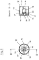
- FIG. 2 shows a sleeve 12 in a top view and in a sectional side view, which can be pushed onto the housing 4 coaxially.
- the sleeve 12 has an opening 13 which, depending on the rotational position of the sleeve 12, exposes one of the recesses 7 or enables the locking button to snap into place.
- a lug 14 is formed on the inside of the sleeve and is guided in the longitudinal groove 9 or in the annular groove 10 of the body 4. With the exception of a certain rotational position, the attachment 14 prevents the sleeve 12 from being pulled off the housing 4.
- the end of the sleeve 12 facing away from the attachment 14 is closed by a wall 15 with an end face 16.
- a circular extension 17 is formed on the inside of the wall 15 and is extended by a segment ring extension 18. The segment ring extension 18 extends over a three-quarter circle, the opening of which is aligned with the opening 13 of the sleeve 12.
- the sealing element which is shown in the left partial figure 3, is pushed onto the segment ring extension 18 and used to seal the various outlet openings.
- a groove 19 in the wall 15 which receives the annular collar of the sealing element.
- a central bore 20 which extends into the shoulder 17 and is connected to the bore 22 of the segment ring shoulder 18 by a small connecting channel 21.
- a recess 23 is further incorporated, which is provided for receiving a seal for the bore 20.
- the bore 20 is sealed off from the pump chamber 6 by the seal and is used to hold, for example, a hose adapter or a pressure gauge, each of which has an inner part with which the seal is pressed inwards and thus a Connection to the pump room 6 is opened.
- a star-shaped groove 52 is arranged on the inside of the wall 15, into which the lug 11 of the housing 4 engages for locking.
- Figure 3 shows a top view and a sectional view of different sealing elements, which consist of a permanently elastic material.
- the left partial figure shows the sealing element 24 for the segment ring extension 18, while the middle partial figures show two seals 25, 26 for the recesses 7 and the right partial figure shows a locking push button 27.
- the sealing element 24 consists of a circular ring section 28 with an integrally formed rounded collar 29 and an annular extension 30, which is double-walled and extends over the circumference of a three-quarter circle.
- the double-walled area of the extension 30 also serves to seal the various outlet openings of the adapter device 1, while the open segment cutout 53 of the extension 30 enables a connection between the respective outlet opening and the pump chamber 6.
- the segment cutout 53 of the extension 30 was chosen so large that the stem of a valve connection, not shown, can be received in order to achieve the smallest possible size of the adapter device 1.
- the sealing element 24 has a set back and partially annularly perforated end face 31, which is designed to be permanently elastic and seals the bore 20 or the connecting channel 21 with respect to the pump chamber 6 in the rest position.
- the end face 31 of the sealing element 24 is pressed inward and thus opens the connecting channel 21 with respect to the pump chamber 6.
- the seals 25, 26 are shown, which are provided for the recess 7 of the housing 4 and all have a square basic shape which is adapted to the recess 7.
- the surface of the seals 25, 26 that lies to the outside has a curvature 32 which is adapted to the radius of the housing 4.
- the seal 25 has a stepped bore 33, which is provided for receiving a valve connection.
- a wedge-shaped annular groove 54 is incorporated, which surrounds the valve edge when plugged on.
- the seal 26, however, has only one through hole 35 and serves to accommodate a conventional bicycle valve.
- the push button 27 shown in the last part of the figure consists of a square base with a central round extension 36.
- a blind hole 38 which is provided for receiving a spring (not shown). Due to the spring force, the push button 27 is pressed outwards through the opening 13 of the sleeve 12 and enables the sleeve 12 to be locked on the housing 4, provided that the opening 13 is aligned with the push button 27.
- FIG. 4 shows the adapter device 1 after assembly in a sectional side view and in a section VII-VII. From the sectional view it can be seen that in the recesses 7 of the housing 4 in the upper position the push button 27 with a spring 39 lying in the blind hole 38 is inserted, while in the right and lower recess 7 a seal 25 or 26 is inserted. The left recess 7, however, is free. In the rotational position of the sleeve 12, the opening 13 is oriented upward, so that the push button 27 is pressed out through the opening 13. The seals 25, 26 are additionally closed by the sleeve 12 in order to avoid contamination. This position practically represents the locking position of the adapter device 1, in which none of the outlet openings is connected to the pump chamber 6.
- the seal with respect to the pump chamber 6 is provided by the sealing element 24, which is pushed onto the segment ring shoulder 18 of the sleeve 12 and points with its open segment cutout 53 in the direction of the push button 27.
- the segment ring projection 18 which is integrally connected to the sleeve 12 is also rotated, so that the segment cutout 53 of the sealing element 24 is rotated in the direction of the outlet opening and at the same time a connection to the pump chamber 6 is established.
- the bore 20 present in the end face 16 is sealed by the end face 31 of the sealing element 24, so that only a single sealing element is required for all outlet openings of the housing 4. Alternatively, there is the possibility of sealing the bore 20 by means of a separate seal.
- the sealing element 24 itself is pushed onto the annular extension 17 of the sleeve 12 and lies with its collar 29 in the annular groove 19, so that the pump chamber 6 is sufficiently sealed off from the sleeve 12.
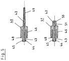
- FIG. 5 shows a ball adapter 40 in the upper illustration and a hose adapter 41 in the lower illustration, each in a sectional side view.
- Both adapters 40, 41 have a central bore 42, which is provided as an air duct.
- An annular one Extension 43 of the adapter 40, 41 has a groove 44 with an O-ring 45, which is provided for sealing the adapter 40, 41 against the sleeve 12.
- the extension 43 is either inserted into the free recess 7 of the sleeve 12 or can be screwed into the bore 20 of the sleeve 12 when used with a threaded connection, the extended extension 43 pressing the elastic end face 31 of the sealing element 24 inwards, so that the bore 42 is connected to the pump chamber 6 and a seal with respect to the sleeve 12 is also ensured via the groove 44 and the O-ring 45.
- a circular ring segment 46 is arranged around the extension 43, which is set back in relation to the extension 43.
- the circular ring segment 46 is integrally formed on the adapter 40, 41 and has at its free end a fastening lug 48, which can snap into an annular groove in the sleeve 12 and ensures secure attachment of the adapter 40, 41 in the free recess 7 of the sleeve 12 .
- the outward-facing end of the adapter 40 consists of a conically tapering valve needle 49 which can be pressed into the tube of a ball, while the tube adapter 41 is provided with a short pin 50 which has a stepped corrugation for fastening a tube (not shown).
- the hose adapter offers the possibility of providing additional external connections, for example for a twin system.
- FIG. 6 shows a top view of a hose connection 60, consisting of a hose adapter 41, a hose 61 and a double valve connection 62.
- the hose adapter 41 essentially corresponds to that of the lower part of FIG. 5, the hose 61 being inserted into the hose adapter 41 instead of the pin 50 .
- the hose is wound in a spiral and has a sufficient length for connection to valves that are difficult to access.
- a double valve connection 62 with a control switch 63, which can assume three possible positions. In the middle position is the zero position, in which both valve connections, the Schrader 64 and the Sclaverand connection 65 are closed.
- connection to the Schrader connection 64 In the upper position an internal connection to the Schrader connection 64 is established and in the lower position a connection to the Sclaverand connection 65 is established, so that a connection to the adapter device (not shown) can be established via the hose 61 and the hose adapter 41.
- the two connections 64, 65 are rotatably mounted on the housing 66 of the double valve connection 62 and thus facilitate screwing onto the respective valve.
- FIG. 7 shows a sectional view through the housing 66 of the double valve connection 62 according to the connecting line VIII-VIII and one according to the connecting line IX-IX.
- the upper part of the figure shows the two valve connections in a sectional plan view, in which the Schrader connection 64 on the left and the Sclaverand connection 65 can be seen on the right, both of which are rotatably fastened in the housing 66.
- the housing 66 has two bores 67, 68, into which the connections 64, 65 protrude with a reduced end 69, 70 and are held by a fastening element 71, which in each case engages in a groove 72, 73.
- the connections 64, 65 are each sealed by an O-ring 74, 75, which is mounted in a groove 76, 77.
- the Sclaverand connection 65 has only a threaded bore 78 for screwing on, while the Schrader connection 64 has a seal 79 and a centrally arranged pin 80 which presses against the valve needle of a Schrader valve and opens it.
- the pin 80 is set back relative to the seal 79, so that the Schrader valve first presses against the seal 79 and is tightly enclosed by the seal, in particular on the inside, before the pin 80 actuates the valve needle.
- the seal 79 has a curvature 81 on the outside, which is pressed against the ring of the Schrader valve and seals particularly well.
- the rear part of the seal 79 is flared in order to ensure that the seal 79 springs back in the valve connection.
- the compressed air is supplied in each case via a connecting duct 82, 83, which are guided through an extension duct 84, 85 to a bore 86 in which the control switch 63 is rotatably mounted.
- the control switch has a rotary head on the outside and a cylindrical subsegment 87 on the inside with a rear end face 88, the cylindrical subsegment 87 extending over a three-quarter circle and receiving an inwardly projecting pin 89 of the hose connection 90, so that the control switch 63 can be rotated in the housing 66 is stored but cannot fall out.
- the sub-segment 87 and the pin 89 simultaneously limit the range of rotation of the control switch 63.
- a seal 91 is arranged with a bore 92, which is non-rotatably connected to the control switch 63 and upon rotation the bore 92 coincides with one of the two extension channels 84, 85.
- the hose connection 90 of the housing 66 consists of a stepped bore 93 with a catch 94, into which a pin 95 of the hose connection 90 engages.
Landscapes
- Engineering & Computer Science (AREA)
- Mechanical Engineering (AREA)
- General Engineering & Computer Science (AREA)
- Quick-Acting Or Multi-Walled Pipe Joints (AREA)
Applications Claiming Priority (2)
| Application Number | Priority Date | Filing Date | Title |
|---|---|---|---|
| DE19518244 | 1995-05-15 | ||
| DE19518244A DE19518244C2 (de) | 1995-05-15 | 1995-05-15 | Adaptervorrichtung |
Publications (2)
| Publication Number | Publication Date |
|---|---|
| EP0743203A1 true EP0743203A1 (fr) | 1996-11-20 |
| EP0743203B1 EP0743203B1 (fr) | 1999-08-04 |
Family
ID=7762238
Family Applications (1)
| Application Number | Title | Priority Date | Filing Date |
|---|---|---|---|
| EP96107653A Expired - Lifetime EP0743203B1 (fr) | 1995-05-15 | 1996-05-14 | Dispositif adaptateur |
Country Status (3)
| Country | Link |
|---|---|
| US (1) | US6003546A (fr) |
| EP (1) | EP0743203B1 (fr) |
| DE (2) | DE19518244C2 (fr) |
Cited By (4)
| Publication number | Priority date | Publication date | Assignee | Title |
|---|---|---|---|---|
| FR2810718A1 (fr) * | 2000-06-21 | 2001-12-28 | Scott Wu | Dispositif de pompage avec un tube pivotant interieur pour differentes valves |
| CN101624089B (zh) * | 2008-07-07 | 2012-10-03 | 烨昆实业有限公司 | 气囊脱离定位安全结构 |
| EP3756871A1 (fr) * | 2019-05-30 | 2020-12-30 | Wen-San Chou | Structure de joint anti-jet de raccordement de compresseur d'air de véhicule |
| EP3797976A1 (fr) * | 2019-09-04 | 2021-03-31 | Wen-San Chou | Structure de joint anti-pulvérisation de tuyau de raccordement de compresseur d'air de véhicule |
Families Citing this family (4)
| Publication number | Priority date | Publication date | Assignee | Title |
|---|---|---|---|---|
| DE10007204C2 (de) * | 2000-02-17 | 2003-03-27 | Raymond A & Cie | Drehbarer Absperrhahn für eine Steckkupplung mit abgewinkeltem Anschlußstutzen |
| US8402986B1 (en) * | 2010-07-27 | 2013-03-26 | Steven S. Gray | Device for deflating and inflating an item |
| US9456701B2 (en) * | 2014-06-13 | 2016-10-04 | Aeris Technology LLC | Valve assembly for controlling fluid communication between fluid chambers, inflatable device, and method |
| WO2018213584A1 (fr) * | 2017-05-17 | 2018-11-22 | Orange Seal | Ensemble corps de valve configurable |
Citations (3)
| Publication number | Priority date | Publication date | Assignee | Title |
|---|---|---|---|---|
| FR437650A (fr) * | 1911-02-23 | 1912-04-25 | Benjamin Eugene Verge | Pompe à air applicable notamment au gonflement des pneumatiques |
| DE592636C (de) * | 1934-02-12 | Theodor Rodehueser | Schlauchlose Handluftpumpe | |
| DE9413154U1 (de) * | 1994-08-04 | 1994-10-13 | Kohn, Andreas, 10243 Berlin | Sattelstützenluftpumpe für zwei verschiedene Ventilarten mit Kleinteilbehälter |
Family Cites Families (7)
| Publication number | Priority date | Publication date | Assignee | Title |
|---|---|---|---|---|
| US2371657A (en) * | 1943-12-30 | 1945-03-20 | Parker Appliance Co | Valve assembly |
| DE1752315U (de) * | 1953-06-01 | 1957-09-12 | Progresswerk Oberkirch Ag | Nippelansatz fuer motorrad-handluftpumpen. |
| US3385321A (en) * | 1965-08-26 | 1968-05-28 | Sealed United Parts Co Inc | Multiport valve |
| US4169491A (en) * | 1977-11-18 | 1979-10-02 | Bajka Engineering Enterprises | Three port two-way diverter valve with integral drain on one output port |
| US4723567A (en) * | 1985-07-19 | 1988-02-09 | Essex Industries, Inc. | Gas flow control valve |
| DE3819771A1 (de) * | 1987-12-18 | 1989-07-06 | Karl Scheffer Klute Gmbh & Co | Handluftpumpe fuer zweiradreifen |
| US5123449A (en) * | 1989-10-20 | 1992-06-23 | Dema Engineering Company | Selector valve |
-
1995
- 1995-05-15 DE DE19518244A patent/DE19518244C2/de not_active Expired - Fee Related
-
1996
- 1996-05-14 EP EP96107653A patent/EP0743203B1/fr not_active Expired - Lifetime
- 1996-05-14 US US08/645,861 patent/US6003546A/en not_active Expired - Fee Related
- 1996-05-14 DE DE59602589T patent/DE59602589D1/de not_active Expired - Fee Related
Patent Citations (3)
| Publication number | Priority date | Publication date | Assignee | Title |
|---|---|---|---|---|
| DE592636C (de) * | 1934-02-12 | Theodor Rodehueser | Schlauchlose Handluftpumpe | |
| FR437650A (fr) * | 1911-02-23 | 1912-04-25 | Benjamin Eugene Verge | Pompe à air applicable notamment au gonflement des pneumatiques |
| DE9413154U1 (de) * | 1994-08-04 | 1994-10-13 | Kohn, Andreas, 10243 Berlin | Sattelstützenluftpumpe für zwei verschiedene Ventilarten mit Kleinteilbehälter |
Cited By (4)
| Publication number | Priority date | Publication date | Assignee | Title |
|---|---|---|---|---|
| FR2810718A1 (fr) * | 2000-06-21 | 2001-12-28 | Scott Wu | Dispositif de pompage avec un tube pivotant interieur pour differentes valves |
| CN101624089B (zh) * | 2008-07-07 | 2012-10-03 | 烨昆实业有限公司 | 气囊脱离定位安全结构 |
| EP3756871A1 (fr) * | 2019-05-30 | 2020-12-30 | Wen-San Chou | Structure de joint anti-jet de raccordement de compresseur d'air de véhicule |
| EP3797976A1 (fr) * | 2019-09-04 | 2021-03-31 | Wen-San Chou | Structure de joint anti-pulvérisation de tuyau de raccordement de compresseur d'air de véhicule |
Also Published As
| Publication number | Publication date |
|---|---|
| EP0743203B1 (fr) | 1999-08-04 |
| DE19518244C2 (de) | 1998-12-17 |
| DE19518244A1 (de) | 1996-11-21 |
| US6003546A (en) | 1999-12-21 |
| DE59602589D1 (de) | 1999-09-09 |
Similar Documents
| Publication | Publication Date | Title |
|---|---|---|
| DE3905722C2 (fr) | ||
| DE69620550T2 (de) | Vorrichtung zur Verbindung mit einer Pumpe | |
| DE2800701C2 (fr) | ||
| EP0005865A2 (fr) | Système de liaison enfichable pour conduites sous pression, en particulier pour conduites de système de freinage | |
| DE202014011547U1 (de) | Vorrichtung zum Abdichten und/oder Aufpumpen von Gegenständen und selbstverschliessende Schraubkupplung | |
| EP1992395A1 (fr) | Filtre, en particulier filtre à air | |
| EP2680937B1 (fr) | Système de filtre muni d'un élément filtrant annulaire | |
| DE3605016A1 (de) | Steckverbindungsvorrichtung mit verdrehsicherung | |
| DE202020102918U1 (de) | Ausbruchschutzstruktur des Verbindungsschlauches eines Luftkompressors für ein Fahrzeug | |
| DE69421510T2 (de) | Ventilanordnung | |
| EP0743203B1 (fr) | Dispositif adaptateur | |
| DE69220381T2 (de) | Belüftete abnehmbare kappe | |
| EP1396671B1 (fr) | Partie réceptrice d'un raccord fluide enfichable | |
| DE102006062921B3 (de) | Anordnung bestehend aus einer handbetätigten gasbetriebenen Vorrichtung, insbesondere Befestigungsvorrichtung, und einer Gaskartusche als Energiequelle für die handbetätigte gasbetriebene Vorrichtung | |
| EP0268948A2 (fr) | Dispositif de fermeture pour bouteilles | |
| DE102005028257A1 (de) | Einrichtung zum Zuführen von Dichtungsflüssigkeit in einen Luftreifen | |
| DE102021002511A1 (de) | Filtervorrichtung | |
| EP4155141B1 (fr) | Dispositif de liaison permettant de relier une valve d'un pneu à une source d'air comprimé | |
| DE1815789C2 (de) | Reifenventil für eine Luftbereifung von Fahrzeugen | |
| EP3328701B1 (fr) | Système d'accouplement, en particulier système d'accouplement pour relier pneumatiquement un système de freinage pneumatique d'un véhicule tracteur et d'une remorque | |
| DE3346614C2 (fr) | ||
| EP1496334A1 (fr) | Boulon pour un point de mesure | |
| DE102013101677B4 (de) | Sicherheitsventil | |
| DE102013101678B3 (de) | Sicherheitsventil | |
| EP0679828B1 (fr) | Connecteur pour conduite pneumatique ou hydraulique et son utilisation dans le domaine dentaire |
Legal Events
| Date | Code | Title | Description |
|---|---|---|---|
| PUAI | Public reference made under article 153(3) epc to a published international application that has entered the european phase |
Free format text: ORIGINAL CODE: 0009012 |
|
| AK | Designated contracting states |
Kind code of ref document: A1 Designated state(s): DE FR GB IT SE |
|
| 17P | Request for examination filed |
Effective date: 19970513 |
|
| RAP3 | Party data changed (applicant data changed or rights of an application transferred) |
Owner name: INNOVATIVE TECHNIK MARKETING (ITM) |
|
| GRAG | Despatch of communication of intention to grant |
Free format text: ORIGINAL CODE: EPIDOS AGRA |
|
| GRAG | Despatch of communication of intention to grant |
Free format text: ORIGINAL CODE: EPIDOS AGRA |
|
| GRAH | Despatch of communication of intention to grant a patent |
Free format text: ORIGINAL CODE: EPIDOS IGRA |
|
| 17Q | First examination report despatched |
Effective date: 19981223 |
|
| GRAH | Despatch of communication of intention to grant a patent |
Free format text: ORIGINAL CODE: EPIDOS IGRA |
|
| GRAA | (expected) grant |
Free format text: ORIGINAL CODE: 0009210 |
|
| AK | Designated contracting states |
Kind code of ref document: B1 Designated state(s): DE FR GB IT SE |
|
| PG25 | Lapsed in a contracting state [announced via postgrant information from national office to epo] |
Ref country code: SE Free format text: THE PATENT HAS BEEN ANNULLED BY A DECISION OF A NATIONAL AUTHORITY Effective date: 19990804 Ref country code: IT Free format text: LAPSE BECAUSE OF FAILURE TO SUBMIT A TRANSLATION OF THE DESCRIPTION OR TO PAY THE FEE WITHIN THE PRE;WARNING: LAPSES OF ITALIAN PATENTS WITH EFFECTIVE DATE BEFORE 2007 MAY HAVE OCCURRED AT ANY TIME BEFORE 2007. THE CORRECT EFFECTIVE DATE MAY BE DIFFERENT FROM THE ONE RECORDED.SCRIBED TIME-LIMIT Effective date: 19990804 Ref country code: GB Free format text: LAPSE BECAUSE OF FAILURE TO SUBMIT A TRANSLATION OF THE DESCRIPTION OR TO PAY THE FEE WITHIN THE PRESCRIBED TIME-LIMIT Effective date: 19990804 Ref country code: FR Free format text: LAPSE BECAUSE OF FAILURE TO SUBMIT A TRANSLATION OF THE DESCRIPTION OR TO PAY THE FEE WITHIN THE PRESCRIBED TIME-LIMIT Effective date: 19990804 |
|
| REF | Corresponds to: |
Ref document number: 59602589 Country of ref document: DE Date of ref document: 19990909 |
|
| EN | Fr: translation not filed | ||
| GBV | Gb: ep patent (uk) treated as always having been void in accordance with gb section 77(7)/1977 [no translation filed] |
Effective date: 19990804 |
|
| PLBE | No opposition filed within time limit |
Free format text: ORIGINAL CODE: 0009261 |
|
| STAA | Information on the status of an ep patent application or granted ep patent |
Free format text: STATUS: NO OPPOSITION FILED WITHIN TIME LIMIT |
|
| 26N | No opposition filed | ||
| PGFP | Annual fee paid to national office [announced via postgrant information from national office to epo] |
Ref country code: DE Payment date: 20050728 Year of fee payment: 10 |
|
| PG25 | Lapsed in a contracting state [announced via postgrant information from national office to epo] |
Ref country code: DE Free format text: LAPSE BECAUSE OF NON-PAYMENT OF DUE FEES Effective date: 20061201 |