EP0743221B1 - Mécanisme de réglage pour sièges de véhicules automobiles - Google Patents
Mécanisme de réglage pour sièges de véhicules automobiles Download PDFInfo
- Publication number
- EP0743221B1 EP0743221B1 EP96103516A EP96103516A EP0743221B1 EP 0743221 B1 EP0743221 B1 EP 0743221B1 EP 96103516 A EP96103516 A EP 96103516A EP 96103516 A EP96103516 A EP 96103516A EP 0743221 B1 EP0743221 B1 EP 0743221B1
- Authority
- EP
- European Patent Office
- Prior art keywords
- release element
- adjusting mechanism
- mechanism according
- clutch
- groove
- Prior art date
- Legal status (The legal status is an assumption and is not a legal conclusion. Google has not performed a legal analysis and makes no representation as to the accuracy of the status listed.)
- Expired - Lifetime
Links
- 230000007246 mechanism Effects 0.000 title claims description 34
- 230000002401 inhibitory effect Effects 0.000 claims description 9
- 230000001419 dependent effect Effects 0.000 claims description 6
- 230000000295 complement effect Effects 0.000 claims description 2
- 230000008878 coupling Effects 0.000 description 8
- 238000010168 coupling process Methods 0.000 description 8
- 238000005859 coupling reaction Methods 0.000 description 8
- 230000005764 inhibitory process Effects 0.000 description 6
- 125000006850 spacer group Chemical group 0.000 description 4
- 210000000078 claw Anatomy 0.000 description 2
- 238000013461 design Methods 0.000 description 2
- 239000002184 metal Substances 0.000 description 2
- 238000005086 pumping Methods 0.000 description 2
- 230000000903 blocking effect Effects 0.000 description 1
- 238000011161 development Methods 0.000 description 1
- 230000018109 developmental process Effects 0.000 description 1
- 238000000034 method Methods 0.000 description 1
- 238000012545 processing Methods 0.000 description 1
- 238000012546 transfer Methods 0.000 description 1
Images


Classifications
-
- B—PERFORMING OPERATIONS; TRANSPORTING
- B60—VEHICLES IN GENERAL
- B60N—SEATS SPECIALLY ADAPTED FOR VEHICLES; VEHICLE PASSENGER ACCOMMODATION NOT OTHERWISE PROVIDED FOR
- B60N2/00—Seats specially adapted for vehicles; Arrangement or mounting of seats in vehicles
- B60N2/02—Seats specially adapted for vehicles; Arrangement or mounting of seats in vehicles the seat or part thereof being movable, e.g. adjustable
- B60N2/22—Seats specially adapted for vehicles; Arrangement or mounting of seats in vehicles the seat or part thereof being movable, e.g. adjustable the back-rest being adjustable
- B60N2/2227—Seats specially adapted for vehicles; Arrangement or mounting of seats in vehicles the seat or part thereof being movable, e.g. adjustable the back-rest being adjustable and provided with braking systems
-
- Y—GENERAL TAGGING OF NEW TECHNOLOGICAL DEVELOPMENTS; GENERAL TAGGING OF CROSS-SECTIONAL TECHNOLOGIES SPANNING OVER SEVERAL SECTIONS OF THE IPC; TECHNICAL SUBJECTS COVERED BY FORMER USPC CROSS-REFERENCE ART COLLECTIONS [XRACs] AND DIGESTS
- Y10—TECHNICAL SUBJECTS COVERED BY FORMER USPC
- Y10T—TECHNICAL SUBJECTS COVERED BY FORMER US CLASSIFICATION
- Y10T74/00—Machine element or mechanism
- Y10T74/15—Intermittent grip type mechanical movement
- Y10T74/1526—Oscillation or reciprocation to intermittent unidirectional motion
- Y10T74/1553—Lever actuator
- Y10T74/1555—Rotary driven element
- Y10T74/1556—Multiple acting
Definitions
- the invention relates to an adjustment mechanism, in particular for seat adjusters in motor vehicles, to implement a reciprocating movement an actuator into an intermittent, same-directional movement an adjusting element.
- a typical example of a conventional adjustment mechanism of this type is a ratchet mechanism, in which a pawl in a toothing of the adjusting member intervenes when the actuator is moved in one direction while when the actuator retracts, the pawl over the teeth of the adjusting element slide.
- a disadvantage of such a ratchet mechanism is that the Jack an uncomfortable when the actuator retracts "rattling" noise. It proves in certain applications also disadvantageous that the pawl and the teeth of the adjusting member cannot intermesh with each other in any position. Above all, such a ratchet has the disadvantage that it allows only one adjustment of the adjusting member in one direction. If adjustment in both directions is desired, this is why a very elaborate mechanism is required, the two in opposite Directional ratchet mechanism and mechanisms for Unlocking the ineffective locking mechanism.
- the object of the invention is a simple and low-noise adjustment mechanism to create, which allows the adjusting element with the help of Actuator to move in opposite directions.
- An essential part of the adjustment mechanism according to the invention is an input-dependent clutch.
- Such a clutch has an output element and two input elements that act as an inhibiting element and release element are called. If a force on the escapement attacks to move it in one direction or another, so both the release element and the output element become independent of the direction moved along. On the other hand, if the force acts on the release element, then only the release element and the escapement element move together in that direction, and the driving force is not on that Transfer output element.
- An example of such an input-dependent clutch is shown in EP 0 497 007 A1.
- Another example of such a clutch is a so-called wrap spring clutch.
- the output element is from surrounded by a wrap spring.
- the escapement acts in every direction on one end of the wrap spring so that it is tighter around the output element closes and thus the adhesion with the output element manufactures.
- the release element acts in the opposite direction in each direction of rotation Point to one of the ends of the wrap spring so that this is the output element releases.
- the actuator forms the inhibition element and the adjusting element the output element of a such clutch. Furthermore, an elastic reset device is provided, between the release element of the clutch and a fixed one Part acts and exerts a restoring force on the release element when this is deflected in any direction from its starting position.
- the invention makes it extremely user-friendly and created practically noiseless adjustment mechanism.
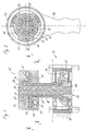
- the adjustment mechanism shown in Fig. 1 is for use in a seat adjuster of a motor vehicle and is used for example for adjustment the backrest, for adjusting a lumbar support and the like.
- the adjustment mechanism comprises an actuation unit 10 and a drive unit 12, which is housed in a box-shaped housing 14.
- the actuating unit 10 has a plate-shaped as a fixed part or cup-shaped carrier 16 on the free end of a tubular Extension 18 of the housing 14 sits and is non-rotatably wedged with it.
- the actuating unit also includes an input-dependent switch Coupling 20 with an actuator serving as an inhibiting element 22, a disc-shaped, rotatably mounted in the carrier 16 release member 24 and an output element in the form of a shaft 26 which through the tubular extension 18 of the housing 14 into the drive unit 12 extends and forms the adjusting member of the adjusting mechanism.
- the clutch 20 is of the type described in EP 0 497 007 A1 becomes.
- the actuator 22, the release member 24 and the shaft 26 are coaxial arranged to each other.
- this bearing shell protrudes outwards facing projections rotatably engaged with the actuator 22.
- a ring 30 made of metal, which is non-rotatable is wedged onto the free end of the shaft 26.
- the inside surface of the cup 28 and the outer surface of the ring 30 form an annular space, of the three pairs of pinch rollers 32. Between Each pair of pinch rollers has an elastic spacer 34 inserted therein (Fig.
- the release element 24 is provided with further axially projecting pins 38 outside the fingers 36, the corresponding counter contours 40 of the actuator 22nd to be engaged. In this way, the actuator is releasably attached held the release element 24, which in turn is locked in the carrier 16.
- the pins 38 each lie radially between two claws projecting from an inner ring 42 of the actuator 22 44.
- the release element 24 and the actuator 22 are thus only within of a very limited game rotatable and able to each other moreover, only together relative to the carrier 16 and / or the ring 30 are rotated.
- the driving torque is not on the actuator 22, but acts on the release element 24, so press the fingers 36 each the pinch roller 32 located in the direction of rotation against the force of the elastic Spacer 34 from the wedge-shaped narrowed area of the gap out between the ring 30 and the bearing shell 28, so that blocking the pinch rollers is prevented.
- the actuator 22 taken in the direction of rotation, while the pinch rollers 32 on the outer surface of the ring 30 unroll. In this case, the ring 30 and the shaft 26 does not participate in the rotary movement. If the force application Via the release element 24, the clutch 20 thus acts in both Directions as a freewheel, that is, the release member 24 and the actuator 22 can rotate independently of the shaft 26.
- a groove 48 which is concentric with the shaft 26 Circular arc runs, as can be seen in Fig. 3.
- This groove 48 takes a correspondingly curved coil spring 50, which with their opposite ends at the ends of the groove 48 as well as at two of supports the release element 24 projecting pin 52.
- At the ends of the Groove 48 closes one running on the same circular arc, however narrower groove 54 in which the relevant pin 52 move can.
- the spring 50 and the pin 52 form an elastic return device, through which the release element 24 after it is in one direction or the other was rotated relative to the carrier 16, again in that shown in Fig. 3 Starting position is turned back.
- the release element provided with the pins 52 is rotated clockwise, so the spring 50 is compressed by the lower pin 52 while the upper end of the spring is supported on the end of the groove 48.
- the pivoting range of the lever 46 is limited in each direction by that one of the pins 52 of the release element 24 at the end of the associated groove 54 strikes.
- By appropriate design of the grooves 48 and 54 and the Spring 50 can thus select the pivoting range of lever 46 as required become.
- the drive unit takes 12 a further input-dependent clutch 56, which according to is constructed on the same principle as the clutch 20 described above Fig. 1 lower end of the shaft 26 forms the release element of this coupling, and the counterpart to the ring 30 is formed by a housing-fixed bush 58, which also serves as a bearing for the shaft 26.
- the inhibition element 60 of the coupling 56 is an annular body, which on its outer circumference, within the housing 14, a radially projecting receptacle 62 in which the end of a Bowden cable can be anchored.
- About the Coupling 56 can thus use the shaft 26 of the Bowden cable in any desired Direction can be adjusted. However, if the other way around by the Bowden cable a force is exerted on the inhibition element 60, so this inhibition element by the clutch 56 in the set position blocked.
- the lumbar support can be used adjust the adjustment mechanism as described, and it is at unactuated adjustment mechanism automatically in the respectively set Position blocked.
- Fig. 4 shows a modified embodiment in which the reset device is housed in the housing 14 of the drive unit 12, so that the Carrier 16 shown in Fig. 1 can be omitted.
- the fixed part that is the spring 50 picks up is here offset by a little to the inside Cover 64 of the housing 14 is formed.
- a hollow shaft 66 is provided here, on the free one End the release element 24 is snapped on and the rotationally fixed to the release element is wedged.
- the hollow shaft 66 carries a flange 68 at the lower end, which is locked with the lid 64 and within a limited range is rotatable relative to the cover 68.
- This flange 68 carries the (in FIG. 4 not shown) pins 52 which cooperate with the spring 50.
- the arcuate groove 48 formed in the carrier 16 only has here a semicircular cross section, and a complementary groove 70 is formed in the release element 24.
- the two grooves 48 and 70 have in Circumferential direction the same length and together form an arcuate Chamber in which the spring 50 is housed. If the release element 24 is in the starting position, the spring 50 is supported with each of its Ends from both the bottom of the groove 70 and the bottom of the groove 48. If however, the release element 24 is turned out of the starting position, the spring 50 is supported only on the bottom of the groove 70 of this release element and with the other end only from the bottom of the groove 48 of the carrier 16, so that the spring is compressed.
- the carrier 16 with a projecting Provided pin 72 which in an arcuate groove 74 of the release member 24 engages.
- the reverse order is also of pin and groove possible.
- the swivel range can also be used as an option be limited that the spring 50 is compressed to block.
- the actuator that Release element and the adjusting member are designed as rotatable parts, it is also possible to design these components as linearly movable elements.
- the Coupling 20 is then designed as a linear coupling, with the ring 30 and the interacting parts are replaced by their respective processing are.
- the adjustment mechanism according to the invention can also initially and / or be combined on the output side with a gear.
- the housing 14 in Figure 1 is a planetary gear Helical gear, a belt drive or the like receives, the input element through the shaft 26 or possibly also through the escapement element 60 of the clutch 56 is formed.
- This gear can be coaxial be arranged to the shaft 26 or laterally next to this shaft.
Landscapes
- Engineering & Computer Science (AREA)
- Aviation & Aerospace Engineering (AREA)
- Transportation (AREA)
- Mechanical Engineering (AREA)
- Mechanical Operated Clutches (AREA)
- Chairs For Special Purposes, Such As Reclining Chairs (AREA)
- Seats For Vehicles (AREA)
- Transmission Devices (AREA)
Claims (11)
- Mécanisme de réglage, en particulier pour des commandes de réglage de sièges dans des véhicules automobiles, servant à convertir un mouvement de va-et-vient d'un organe d'actionnement (22) en un mouvement intermittent de même sens d'un organe de réglage (26), caractérisé par :un accouplement (20) manoeuvré en fonction de l'entrée, qui accouple un élément d'arrêt et un élément de libération (24) dans les deux directions de rotation avec un élément de sortie lorsque l'introduction de force s'effectue à travers l'élément d'arrêt, et qui agit dans les deux directions comme dispositif à roue libre entre, d'une part, l'élément d'arrêt et l'élément de libération et, d'autre part, l'élément de sortie lorsque l'introduction de force s'effectue à travers l'élément de libération, et dont l'élément d'arrêt est formé par l'organe d'actionnement (22) tandis que l'élément de sortie est formé par l'organe de réglage (26), etun dispositif de rappel élastique (48, 50, 52 ; 70) qui agit entre l'élément de libération (24) et une partie fixe (16 ; 64) et exerce une force de rappel sur l'élément de libération (24) lorsque celui-ci est dévié dans une direction quelconque à partir de sa position initiale.
- Mécanisme de réglage selon la revendication 1, caractérisé en ce que l'accouplement (20) comporte plusieurs paires de corps d'arrêt (32) qui sont logés dans un interstice entre une surface de roulement de la coquille de support (28) montée fixe par rapport à l'organe d'actionnement (22) et une surface de roulement de l'anneau (30) montée fixe par rapport à l'organe de réglage (26), en ce qu'un corps d'écartement élastique (34) est inséré entre les corps d'arrêt (32) de chaque paire tandis que les portions de l'interstice situées entre les corps d'arrêt des différentes paires sont comblées par des doigts (36) de l'élément de libération (24), en ce que l'interstice se rétrécit en forme de coin à partir de chaque corps d'écartement (34) en direction des doigts voisins (36), et en ce que l'organe d'actionnement (22) est accouplé avec l'élément de libération (24) et n'est mobile dans chaque direction par rapport à celui-ci qu'en fonction d'un jeu limité.
- Mécanisme de réglage selon la revendication 1, caractérisé en ce que l'accouplement (20) est un accouplement à ressort enroulé.
- Mécanisme de réglage selon une des revendications précédentes, caractérisé en ce que le dispositif de rappel comprend un ressort hélicoïdal (50), et en ce que l'élément de libération (24) ainsi que la partie fixe (16 ; 64) forment à chacune des extrémités du ressort hélicoïdal un contre-appui pour le ressort hélicoïdal.
- Mécanisme de réglage selon la revendication 4, caractérisé en ce que l'organe d'actionnement (22), l'élément de libération (24) et l'organe de réglage (26) peuvent tourner autour d'un axe commun par rapport à la partie fixe (16 ; 64), et en ce que le ressort hélicoïdal (50) est logé dans une rainure en arc de cercle (48 ; 70) de la partie fixe et/ou de l'élément de libération, ladite rainure étant concentrique audit axe de rotation.
- Mécanisme de réglage selon la revendication 4 ou 5, caractérisé en ce que le ressort hélicoïdal (50) est logé dans une rainure (48) de la partie fixe (16 ; 64) ou de l'élément de libération (24), en ce que les extrémités de cette rainure (48) forment les contre-appuis de l'un des composants correspondants (16 ; 64) pour les extrémités du ressort hélicoïdal (50), et en ce que les contre-appuis de l'autre composant (24) sont formés par des tétons (52) qui sont mobiles dans la rainure (48) recevant le ressort hélicoïdal (50) ainsi que dans des rainures plus étroites (54) prolongeant ladite rainure.
- Mécanisme de réglage selon la revendication 4 ou 5, caractérisé en ce que le ressort hélicoïdal (50) est logé pour moitié dans une rainure (48) de la partie fixe (16 ; 64) et pour moitié dans une rainure (70), complémentaire à la précédente, de l'élément de libération (24), et en que les extrémités des deux rainures forment les contre-appuis pour le ressort hélicoïdal.
- Mécanisme de réglage selon une des revendications précédentes, caractérisé en ce que l'organe de réglage (26) est un arbre, et en ce que l'organe d'actionnement (22) et l'élément de libération (24) sont disposés coaxialement sur ledit arbre.
- Mécanisme de réglage selon une des revendications précédentes, caractérisé par un accouplement supplémentaire (56) manoeuvré en fonction de l'entrée, dont l'élément de libération est formé par l'organe de réglage (26) et dont l'élément de sortie est un fourreau (58) solidaire du boítier, de sorte que l'élément d'arrêt (60) dudit accouplement peut être réglé par l'intermédiaire de l'organe de réglage (26) et bloqué dans la position de réglage choisie par l'intermédiaire du fourreau (58) solidaire du boítier.
- Mécanisme de réglage selon la revendication 9, caractérisé en ce que l'élément d'arrêt (60) de l'accouplement supplémentaire (56) comporte un logement (62) pour au moins une extrémité d'un câble de commande.
- Mécanisme de réglage selon une des revendications précédentes, caractérisé en ce que l'organe de réglage (26) est accouplé indirectement ou directement à une transmission.
Applications Claiming Priority (2)
| Application Number | Priority Date | Filing Date | Title |
|---|---|---|---|
| DE19518424A DE19518424C2 (de) | 1995-05-19 | 1995-05-19 | Verstellmechanismus |
| DE19518424 | 1995-05-19 |
Publications (4)
| Publication Number | Publication Date |
|---|---|
| EP0743221A2 EP0743221A2 (fr) | 1996-11-20 |
| EP0743221A3 EP0743221A3 (fr) | 1998-07-01 |
| EP0743221B1 true EP0743221B1 (fr) | 2001-06-27 |
| EP0743221B2 EP0743221B2 (fr) | 2007-11-14 |
Family
ID=7762360
Family Applications (1)
| Application Number | Title | Priority Date | Filing Date |
|---|---|---|---|
| EP96103516A Expired - Lifetime EP0743221B2 (fr) | 1995-05-19 | 1996-03-07 | Mécanisme de réglage pour sièges de véhicules automobiles |
Country Status (4)
| Country | Link |
|---|---|
| US (1) | US5794479A (fr) |
| EP (1) | EP0743221B2 (fr) |
| DE (2) | DE19518424C2 (fr) |
| ES (1) | ES2158168T5 (fr) |
Cited By (2)
| Publication number | Priority date | Publication date | Assignee | Title |
|---|---|---|---|---|
| DE102013015500A1 (de) * | 2013-07-11 | 2015-01-15 | Johnson Controls Gmbh | VERSTELLVORRlCHTUNG MlT ElNEM FESTEN ELEMENT, ElNEM VERSTELLBAREN ELEMENT UND ElNER ERSTEN ARRETIERUNGSVORRICHTUNG UND EINER SCHLINGFEDER |
| DE202015103949U1 (de) | 2015-07-28 | 2016-11-02 | Rollax Gmbh & Co. Kg | Sitzversteller mit Zusatzverriegelung |
Families Citing this family (45)
| Publication number | Priority date | Publication date | Assignee | Title |
|---|---|---|---|---|
| DE19725899C2 (de) | 1997-06-13 | 1999-10-28 | Brose Fahrzeugteile | Beidseitig wirkender Verstellantrieb |
| FR2766773B1 (fr) * | 1997-07-30 | 1999-10-15 | Faure Bertrand Equipements Sa | Dispositif de blocage notamment pour siege de vehicule automobile |
| DE29715257U1 (de) * | 1997-08-26 | 1997-12-04 | Atlas Copco Electric Tools GmbH, 71364 Winnenden | Mitnahmevorrichtung |
| DE19750260A1 (de) * | 1997-11-13 | 1999-05-20 | Schaeffler Waelzlager Kg | Klemmgesperre |
| US6068097A (en) * | 1997-12-24 | 2000-05-30 | Ntn Corporation | Dual-mode two-way clutch |
| DE29802055U1 (de) * | 1998-02-10 | 1999-06-10 | Schwarzbich, Jörg, 33615 Bielefeld | Sitzversteller |
| DE29809418U1 (de) | 1998-05-26 | 1999-09-30 | Schwarzbich, Jörg, 33615 Bielefeld | Verstellmechanismus |
| DE19831205C2 (de) * | 1998-07-01 | 2000-06-21 | Brose Fahrzeugteile | Stufenloser manueller Antrieb |
| DE19845365A1 (de) * | 1998-10-02 | 2000-04-06 | Schaeffler Waelzlager Ohg | Schaltbares Klemmgesperre |
| DE19855004C5 (de) | 1998-11-20 | 2006-12-28 | Brose Fahrzeugteile Gmbh & Co. Kommanditgesellschaft, Coburg | Antrieb für Verstellvorrichtungen in Kraftfahrzeugen |
| DE19854945A1 (de) * | 1998-11-27 | 2000-05-31 | Schaeffler Waelzlager Ohg | Klemmrollenschaltwerk |
| DE19854931A1 (de) | 1998-11-27 | 2000-05-31 | Schaeffler Waelzlager Ohg | Stelleinrichtung, insbesondere zur Verstellung eines Kraftfahrzeugsitzes |
| DE19915054C2 (de) | 1999-04-01 | 2001-03-22 | Schukra Geraetebau Ges M B H | Verstellvorrichtung |
| FR2792264B1 (fr) * | 1999-04-16 | 2001-06-15 | Faure Bertrand Equipements Sa | Mecanisme de reglage irreversible |
| DE19949485A1 (de) * | 1999-10-14 | 2001-04-19 | Schaeffler Waelzlager Ohg | Klemmgesperre |
| DE19952633C1 (de) | 1999-10-21 | 2001-09-13 | Brose Fahrzeugteile | Beidseitig wirkender Antrieb für Verstellvorrichtungen in Kraftfahrzeugen |
| US6334651B1 (en) | 2000-02-01 | 2002-01-01 | Schukra Geratebau Gmbh | Lumbar support adjusting mechanism |
| DE10026007A1 (de) * | 2000-05-25 | 2001-11-29 | Schaeffler Waelzlager Ohg | Vorrichtung zur Verstellung des Abstandes zwischen einer Kopfstütze und einer Rückenlehne |
| FR2809999B1 (fr) * | 2000-06-08 | 2002-09-27 | Faure Bertrand Equipements Sa | Mecanisme de reglage |
| FR2826320B1 (fr) * | 2001-06-21 | 2003-09-19 | Faurecia Sieges Automobile | Mecanisme de reglage irreversible et siege de vehicule comportant un tel mecanisme |
| FR2826319B1 (fr) * | 2001-06-21 | 2003-09-19 | Faurecia Sieges Automobile | Mecanisme de reglage irreversible et siege de vehicule comportant un tel mecanisme |
| US6637575B2 (en) | 2001-10-03 | 2003-10-28 | L & P Property Management Company | Apparatus and method for thin profile ratchet actuator |
| US6691851B2 (en) | 2001-10-03 | 2004-02-17 | L & P Property Management Company | Apparatus and method for ratchet actuator |
| DE60213437T2 (de) * | 2001-10-03 | 2007-01-04 | L&P Property Management Co., South Gate | Vorrichtung und verfahren für rückstellunggerät |
| US6688443B2 (en) | 2001-11-07 | 2004-02-10 | L & P Property Management Company | Apparatus and method for double clutch actuator |
| US6880424B2 (en) * | 2001-12-07 | 2005-04-19 | L & P Property Management Company | Apparatus for telescoping actuator |
| US6668679B2 (en) | 2001-12-07 | 2003-12-30 | L & P Property Management Company | Apparatus and method for pulley actuator |
| US20040080197A1 (en) * | 2002-10-25 | 2004-04-29 | Robert Kopetzky | Transmission amplifier for bowden cables and method of using the same |
| US6957596B2 (en) | 2002-10-25 | 2005-10-25 | L&P Property Management Company | Apparatus and method for braking ergonomic support actuator |
| US6971719B2 (en) * | 2003-03-21 | 2005-12-06 | L & P Property Management Company | Clutch actuator surface apparatus and method |
| KR100490313B1 (ko) * | 2003-07-12 | 2005-05-18 | 주식회사다스 | 자동차용 시트쿠션 펌핑디바이스 |
| US6951270B2 (en) * | 2004-01-20 | 2005-10-04 | L & P Property Management Company | Silent ratchet actuator |
| EP2506404A3 (fr) * | 2004-02-06 | 2013-07-31 | L&P Property Management Company | Appareil et procédé pour actionneur en ligne |
| DE102004009331B4 (de) * | 2004-02-26 | 2005-12-01 | Fico Cables, Lda. | Betätigungsmechanismus für Bowdenzüge |
| DE102004009332B4 (de) * | 2004-02-26 | 2006-05-11 | Fico Cables, Lda. | Betätigungsmechanismus für Bowdenzüge |
| DE102004034229A1 (de) * | 2004-07-15 | 2006-02-16 | Schukra Gerätebau AG | Betätigungseinrichtung |
| US8136423B2 (en) * | 2005-01-25 | 2012-03-20 | Schukra of North America Co. | Multiple turn mechanism for manual lumbar support adjustment |
| DE102005018148B4 (de) * | 2005-04-20 | 2021-05-12 | Schaeffler Technologies AG & Co. KG | Klemmkörperschaltwerk, insbesondere zur Verstellung eines Kraftfahrzeugsitzes |
| DE102006023363B4 (de) * | 2006-05-17 | 2010-08-12 | Johnson Controls Gmbh | Verstellvorrichtung für einen Fahrzeugsitz |
| DE102006026392A1 (de) * | 2006-06-07 | 2007-12-13 | Schaeffler Kg | Schrittschaltwerk, insbesondere für eine Sitzverstellung |
| ES2319145B1 (es) * | 2006-12-27 | 2009-12-11 | Figueras International Seating, S.A. | Sistema de giro automatico para asientos basculantes de sillas o butacas. |
| US7677666B2 (en) | 2008-01-09 | 2010-03-16 | Bae Industries, Inc. | Disc recliner assembly incorporated into a seatback/seat base pivot associated with a vehicle seat |
| DE102009005044B4 (de) * | 2009-01-14 | 2025-10-02 | Brose Fahrzeugteile SE & Co. Kommanditgesellschaft, Coburg | Verstellvorrichtung zum Verstellen eines Fahrzeugsitzteils |
| EP2279900B1 (fr) | 2009-07-30 | 2012-06-06 | Rollax GmbH & Co. KG | Armature réglable pour sièges de véhicule automobile |
| BR112013002161B1 (pt) | 2010-07-29 | 2020-12-15 | Rollax Gmbh & Co. Kg | Mecanismo de acoplamento por aperto, método para sua fabricação e mecanismo de ajuste para assentos de veículos |
Family Cites Families (15)
| Publication number | Priority date | Publication date | Assignee | Title |
|---|---|---|---|---|
| DE604395C (fr) * | ||||
| US2066167A (en) * | 1932-07-18 | 1936-12-29 | Guy E Swartz | Shaft operating and locking device |
| DE804876C (de) * | 1950-02-05 | 1953-06-25 | Eugen Stoesser | Selbsthemmende Transport- und Schaltvorrichtung |
| DE1242948B (de) * | 1960-03-22 | 1967-06-22 | Johanna Ludwig Geb Henning | Einstellbares Gelenk |
| DE3115942A1 (de) * | 1981-04-22 | 1982-11-18 | Audi Nsu Auto Union Ag, 7107 Neckarsulm | Einrichtung zum verstellen der rueckenlehne eines kraftfahrzeugsitzes |
| US4781415A (en) * | 1986-06-30 | 1988-11-01 | Itt Corporation | Reclining infinitely variable seat latch with dual locking mechanisms apparatus and method |
| JP2528140B2 (ja) * | 1987-09-08 | 1996-08-28 | エヌティエヌ株式会社 | クラッチ装置 |
| DE3734363A1 (de) * | 1987-10-10 | 1989-04-20 | Burger Soehne | Vorrichtung zum verstellen eines kraftfahrzeugsitzes |
| DE3839732A1 (de) * | 1988-11-24 | 1990-06-07 | Rentrop Hubbert & Wagner | Bremse fuer ein verstellgetriebe von kraftfahrzeugsitzen |
| JP2804144B2 (ja) * | 1990-03-01 | 1998-09-24 | エヌエスケー・ワーナー株式会社 | 円筒コロ型二方向クラッチ |
| DE9101110U1 (de) * | 1991-02-01 | 1992-02-27 | Schwarzbich, Jörg, 4800 Bielefeld | Getriebe für die Übertragung einer Drehbewegung in beiden Drehsinnen |
| DE4134353C2 (de) * | 1991-10-17 | 2001-05-03 | Schaeffler Waelzlager Ohg | Als Rollenfreilauf ausgebildete Kupplung zur Übertragung eines in beiden Drehrichtungen wirksamen Drehmoments |
| DE4321335C2 (de) † | 1993-06-26 | 1997-06-05 | Daimler Benz Ag | Verstellvorrichtung |
| DE9319848U1 (de) * | 1993-12-23 | 1995-01-26 | Schwarzbich, Jörg, 33615 Bielefeld | Sitzverstellung |
| DE9408426U1 (de) * | 1994-05-24 | 1995-06-29 | Schwarzbich, Jörg, 33615 Bielefeld | Freilaufbremse |
-
1995
- 1995-05-19 DE DE19518424A patent/DE19518424C2/de not_active Expired - Fee Related
-
1996
- 1996-03-07 DE DE59607153T patent/DE59607153D1/de not_active Expired - Lifetime
- 1996-03-07 EP EP96103516A patent/EP0743221B2/fr not_active Expired - Lifetime
- 1996-03-07 ES ES96103516T patent/ES2158168T5/es not_active Expired - Lifetime
- 1996-05-07 US US08/646,074 patent/US5794479A/en not_active Expired - Lifetime
Cited By (3)
| Publication number | Priority date | Publication date | Assignee | Title |
|---|---|---|---|---|
| DE102013015500A1 (de) * | 2013-07-11 | 2015-01-15 | Johnson Controls Gmbh | VERSTELLVORRlCHTUNG MlT ElNEM FESTEN ELEMENT, ElNEM VERSTELLBAREN ELEMENT UND ElNER ERSTEN ARRETIERUNGSVORRICHTUNG UND EINER SCHLINGFEDER |
| DE202015103949U1 (de) | 2015-07-28 | 2016-11-02 | Rollax Gmbh & Co. Kg | Sitzversteller mit Zusatzverriegelung |
| US10611285B2 (en) | 2015-07-28 | 2020-04-07 | Rollax Gmbh & Co. Kg | Seat adjuster with additional locking means |
Also Published As
| Publication number | Publication date |
|---|---|
| DE19518424A1 (de) | 1996-11-21 |
| EP0743221B2 (fr) | 2007-11-14 |
| ES2158168T3 (es) | 2001-09-01 |
| EP0743221A3 (fr) | 1998-07-01 |
| DE59607153D1 (de) | 2001-08-02 |
| ES2158168T5 (es) | 2008-04-16 |
| US5794479A (en) | 1998-08-18 |
| EP0743221A2 (fr) | 1996-11-20 |
| DE19518424C2 (de) | 1998-11-26 |
Similar Documents
| Publication | Publication Date | Title |
|---|---|---|
| EP0743221B2 (fr) | Mécanisme de réglage pour sièges de véhicules automobiles | |
| EP1202870B1 (fr) | Mecanisme de reglage pour sieges dotes d'un dossier a inclinaison reglable, en particulier pour sieges de vehicules | |
| EP0497007B1 (fr) | Transmission pour le transfert d'un mouvement rotatif dans les deux sens de rotation | |
| DE19653722C2 (de) | Beidseitig wirkende Verstellvorrichtung | |
| DE102004013272B3 (de) | Neigungsverstellbeschlag für die Rückenlehne eines Kraftfahrzeugsitzes | |
| EP0751032B1 (fr) | Dispositif de réglage | |
| DE3915959C2 (fr) | ||
| EP0979179B2 (fr) | Dispositif de réglage de siège | |
| EP0960765B1 (fr) | Mécanisme de réglage | |
| EP1893437A1 (fr) | Ferrure pour siege de vehicule | |
| EP1530523B1 (fr) | Accoudoir | |
| EP1451035B1 (fr) | Repose-bras | |
| EP0662403A2 (fr) | Réglage d'un siège | |
| DE19956984B4 (de) | Fahrzeugsitz mit Gelenkmechanismus | |
| DE10018108C2 (de) | Getriebebeschlag für einen Fahrzeugsitzeinsteller | |
| DE19527374C2 (de) | Taumelbeschlag für Fahrzeugsitze, insbesondere Kraftfahrzeugsitze | |
| DE4436096C2 (de) | Klinkenschaltwerk zum Antrieb einer Verstellvorrichtungen für einen Fahrzeugsitz | |
| DE69704202T2 (de) | Neigungsverstellungsmechanismus für einen Sitz | |
| DE10157274B4 (de) | Verstellbeschlag für Kraftfahrzeugsitze | |
| DE102022107408B3 (de) | Freilaufeinrichtung sowie Kupplungsanordnung mit der Freilaufeinrichtung | |
| DE10232029B4 (de) | Neigungsverstellbeschlag für Rückenlehnen von Kraftfahrzeugsitzen | |
| EP1813466B1 (fr) | Système d'articulation | |
| DE3938081C2 (de) | Einziehvorrichtung für Sicherheitsgurte in Kraftfahrzeugen | |
| DE19744944A1 (de) | Verstellmechanik für eine stufenlose Dreh-Verstellung eines Abtriebs-Wirkteiles | |
| DE10348823B4 (de) | Antrieb für einen Fahrzeugsitzeinsteller |
Legal Events
| Date | Code | Title | Description |
|---|---|---|---|
| PUAI | Public reference made under article 153(3) epc to a published international application that has entered the european phase |
Free format text: ORIGINAL CODE: 0009012 |
|
| AK | Designated contracting states |
Kind code of ref document: A2 Designated state(s): DE ES FR GB IT SE |
|
| PUAL | Search report despatched |
Free format text: ORIGINAL CODE: 0009013 |
|
| AK | Designated contracting states |
Kind code of ref document: A3 Designated state(s): DE ES FR GB IT SE |
|
| 17P | Request for examination filed |
Effective date: 19980811 |
|
| GRAG | Despatch of communication of intention to grant |
Free format text: ORIGINAL CODE: EPIDOS AGRA |
|
| 17Q | First examination report despatched |
Effective date: 20000509 |
|
| GRAG | Despatch of communication of intention to grant |
Free format text: ORIGINAL CODE: EPIDOS AGRA |
|
| GRAH | Despatch of communication of intention to grant a patent |
Free format text: ORIGINAL CODE: EPIDOS IGRA |
|
| GRAH | Despatch of communication of intention to grant a patent |
Free format text: ORIGINAL CODE: EPIDOS IGRA |
|
| GRAA | (expected) grant |
Free format text: ORIGINAL CODE: 0009210 |
|
| AK | Designated contracting states |
Kind code of ref document: B1 Designated state(s): DE ES FR GB IT SE |
|
| REF | Corresponds to: |
Ref document number: 59607153 Country of ref document: DE Date of ref document: 20010802 |
|
| REG | Reference to a national code |
Ref country code: ES Ref legal event code: FG2A Ref document number: 2158168 Country of ref document: ES Kind code of ref document: T3 |
|
| ITF | It: translation for a ep patent filed | ||
| GBT | Gb: translation of ep patent filed (gb section 77(6)(a)/1977) |
Effective date: 20010920 |
|
| ET | Fr: translation filed | ||
| REG | Reference to a national code |
Ref country code: GB Ref legal event code: IF02 |
|
| PLBQ | Unpublished change to opponent data |
Free format text: ORIGINAL CODE: EPIDOS OPPO |
|
| PLBI | Opposition filed |
Free format text: ORIGINAL CODE: 0009260 |
|
| PLBF | Reply of patent proprietor to notice(s) of opposition |
Free format text: ORIGINAL CODE: EPIDOS OBSO |
|
| 26 | Opposition filed |
Opponent name: BROSE FAHRZEUGTEILE GMBH & CO. KG, COBURG Effective date: 20020327 |
|
| PLBF | Reply of patent proprietor to notice(s) of opposition |
Free format text: ORIGINAL CODE: EPIDOS OBSO |
|
| RDAF | Communication despatched that patent is revoked |
Free format text: ORIGINAL CODE: EPIDOSNREV1 |
|
| APBP | Date of receipt of notice of appeal recorded |
Free format text: ORIGINAL CODE: EPIDOSNNOA2O |
|
| APBQ | Date of receipt of statement of grounds of appeal recorded |
Free format text: ORIGINAL CODE: EPIDOSNNOA3O |
|
| APAA | Appeal reference recorded |
Free format text: ORIGINAL CODE: EPIDOS REFN |
|
| APAH | Appeal reference modified |
Free format text: ORIGINAL CODE: EPIDOSCREFNO |
|
| APBU | Appeal procedure closed |
Free format text: ORIGINAL CODE: EPIDOSNNOA9O |
|
| PUAH | Patent maintained in amended form |
Free format text: ORIGINAL CODE: 0009272 |
|
| STAA | Information on the status of an ep patent application or granted ep patent |
Free format text: STATUS: PATENT MAINTAINED AS AMENDED |
|
| 27A | Patent maintained in amended form |
Effective date: 20071114 |
|
| AK | Designated contracting states |
Kind code of ref document: B2 Designated state(s): DE ES FR GB IT SE |
|
| GBTA | Gb: translation of amended ep patent filed (gb section 77(6)(b)/1977) | ||
| REG | Reference to a national code |
Ref country code: SE Ref legal event code: RPEO |
|
| REG | Reference to a national code |
Ref country code: ES Ref legal event code: DC2A Date of ref document: 20071228 Kind code of ref document: T5 |
|
| ET3 | Fr: translation filed ** decision concerning opposition | ||
| PLAB | Opposition data, opponent's data or that of the opponent's representative modified |
Free format text: ORIGINAL CODE: 0009299OPPO |
|
| PGFP | Annual fee paid to national office [announced via postgrant information from national office to epo] |
Ref country code: IT Payment date: 20110224 Year of fee payment: 16 Ref country code: FR Payment date: 20110315 Year of fee payment: 16 Ref country code: SE Payment date: 20110302 Year of fee payment: 16 |
|
| PGFP | Annual fee paid to national office [announced via postgrant information from national office to epo] |
Ref country code: ES Payment date: 20110221 Year of fee payment: 16 Ref country code: DE Payment date: 20110330 Year of fee payment: 16 Ref country code: GB Payment date: 20110301 Year of fee payment: 16 |
|
| REG | Reference to a national code |
Ref country code: SE Ref legal event code: EUG |
|
| PG25 | Lapsed in a contracting state [announced via postgrant information from national office to epo] |
Ref country code: SE Free format text: LAPSE BECAUSE OF NON-PAYMENT OF DUE FEES Effective date: 20120308 |
|
| GBPC | Gb: european patent ceased through non-payment of renewal fee |
Effective date: 20120307 |
|
| REG | Reference to a national code |
Ref country code: FR Ref legal event code: ST Effective date: 20121130 |
|
| REG | Reference to a national code |
Ref country code: DE Ref legal event code: R119 Ref document number: 59607153 Country of ref document: DE Effective date: 20121002 |
|
| PG25 | Lapsed in a contracting state [announced via postgrant information from national office to epo] |
Ref country code: FR Free format text: LAPSE BECAUSE OF NON-PAYMENT OF DUE FEES Effective date: 20120402 Ref country code: GB Free format text: LAPSE BECAUSE OF NON-PAYMENT OF DUE FEES Effective date: 20120307 |
|
| PG25 | Lapsed in a contracting state [announced via postgrant information from national office to epo] |
Ref country code: IT Free format text: LAPSE BECAUSE OF NON-PAYMENT OF DUE FEES Effective date: 20120307 |
|
| REG | Reference to a national code |
Ref country code: ES Ref legal event code: FD2A Effective date: 20130710 |
|
| PG25 | Lapsed in a contracting state [announced via postgrant information from national office to epo] |
Ref country code: ES Free format text: LAPSE BECAUSE OF NON-PAYMENT OF DUE FEES Effective date: 20120308 |
|
| PG25 | Lapsed in a contracting state [announced via postgrant information from national office to epo] |
Ref country code: DE Free format text: LAPSE BECAUSE OF NON-PAYMENT OF DUE FEES Effective date: 20121002 |