EP0743416A1 - Dispositif d'entraînement pour un panneau de porte - Google Patents
Dispositif d'entraînement pour un panneau de porte Download PDFInfo
- Publication number
- EP0743416A1 EP0743416A1 EP96108031A EP96108031A EP0743416A1 EP 0743416 A1 EP0743416 A1 EP 0743416A1 EP 96108031 A EP96108031 A EP 96108031A EP 96108031 A EP96108031 A EP 96108031A EP 0743416 A1 EP0743416 A1 EP 0743416A1
- Authority
- EP
- European Patent Office
- Prior art keywords
- driver
- drive
- door leaf
- drive device
- guide rail
- Prior art date
- Legal status (The legal status is an assumption and is not a legal conclusion. Google has not performed a legal analysis and makes no representation as to the accuracy of the status listed.)
- Ceased
Links
Images


Classifications
-
- E—FIXED CONSTRUCTIONS
- E05—LOCKS; KEYS; WINDOW OR DOOR FITTINGS; SAFES
- E05F—DEVICES FOR MOVING WINGS INTO OPEN OR CLOSED POSITION; CHECKS FOR WINGS; WING FITTINGS NOT OTHERWISE PROVIDED FOR, CONCERNED WITH THE FUNCTIONING OF THE WING
- E05F15/00—Power-operated mechanisms for wings
- E05F15/60—Power-operated mechanisms for wings using electrical actuators
- E05F15/603—Power-operated mechanisms for wings using electrical actuators using rotary electromotors
- E05F15/665—Power-operated mechanisms for wings using electrical actuators using rotary electromotors for vertically-sliding wings
- E05F15/668—Power-operated mechanisms for wings using electrical actuators using rotary electromotors for vertically-sliding wings for overhead wings
- E05F15/681—Power-operated mechanisms for wings using electrical actuators using rotary electromotors for vertically-sliding wings for overhead wings operated by flexible elongated pulling elements, e.g. belts
- E05F15/684—Power-operated mechanisms for wings using electrical actuators using rotary electromotors for vertically-sliding wings for overhead wings operated by flexible elongated pulling elements, e.g. belts by chains
-
- E—FIXED CONSTRUCTIONS
- E05—LOCKS; KEYS; WINDOW OR DOOR FITTINGS; SAFES
- E05F—DEVICES FOR MOVING WINGS INTO OPEN OR CLOSED POSITION; CHECKS FOR WINGS; WING FITTINGS NOT OTHERWISE PROVIDED FOR, CONCERNED WITH THE FUNCTIONING OF THE WING
- E05F15/00—Power-operated mechanisms for wings
- E05F15/60—Power-operated mechanisms for wings using electrical actuators
- E05F15/603—Power-operated mechanisms for wings using electrical actuators using rotary electromotors
- E05F15/665—Power-operated mechanisms for wings using electrical actuators using rotary electromotors for vertically-sliding wings
- E05F15/668—Power-operated mechanisms for wings using electrical actuators using rotary electromotors for vertically-sliding wings for overhead wings
- E05F15/681—Power-operated mechanisms for wings using electrical actuators using rotary electromotors for vertically-sliding wings for overhead wings operated by flexible elongated pulling elements, e.g. belts
-
- E—FIXED CONSTRUCTIONS
- E05—LOCKS; KEYS; WINDOW OR DOOR FITTINGS; SAFES
- E05Y—INDEXING SCHEME ASSOCIATED WITH SUBCLASSES E05D AND E05F, RELATING TO CONSTRUCTION ELEMENTS, ELECTRIC CONTROL, POWER SUPPLY, POWER SIGNAL OR TRANSMISSION, USER INTERFACES, MOUNTING OR COUPLING, DETAILS, ACCESSORIES, AUXILIARY OPERATIONS NOT OTHERWISE PROVIDED FOR, APPLICATION THEREOF
- E05Y2201/00—Constructional elements; Accessories therefor
- E05Y2201/20—Brakes; Disengaging means; Holders; Stops; Valves; Accessories therefor
- E05Y2201/218—Holders
- E05Y2201/22—Locks
-
- E—FIXED CONSTRUCTIONS
- E05—LOCKS; KEYS; WINDOW OR DOOR FITTINGS; SAFES
- E05Y—INDEXING SCHEME ASSOCIATED WITH SUBCLASSES E05D AND E05F, RELATING TO CONSTRUCTION ELEMENTS, ELECTRIC CONTROL, POWER SUPPLY, POWER SIGNAL OR TRANSMISSION, USER INTERFACES, MOUNTING OR COUPLING, DETAILS, ACCESSORIES, AUXILIARY OPERATIONS NOT OTHERWISE PROVIDED FOR, APPLICATION THEREOF
- E05Y2201/00—Constructional elements; Accessories therefor
- E05Y2201/20—Brakes; Disengaging means; Holders; Stops; Valves; Accessories therefor
- E05Y2201/23—Actuation thereof
- E05Y2201/232—Actuation thereof by automatically acting means
- E05Y2201/24—Actuation thereof by automatically acting means using lost motion
-
- E—FIXED CONSTRUCTIONS
- E05—LOCKS; KEYS; WINDOW OR DOOR FITTINGS; SAFES
- E05Y—INDEXING SCHEME ASSOCIATED WITH SUBCLASSES E05D AND E05F, RELATING TO CONSTRUCTION ELEMENTS, ELECTRIC CONTROL, POWER SUPPLY, POWER SIGNAL OR TRANSMISSION, USER INTERFACES, MOUNTING OR COUPLING, DETAILS, ACCESSORIES, AUXILIARY OPERATIONS NOT OTHERWISE PROVIDED FOR, APPLICATION THEREOF
- E05Y2201/00—Constructional elements; Accessories therefor
- E05Y2201/40—Motors; Magnets; Springs; Weights; Accessories therefor
- E05Y2201/43—Motors
- E05Y2201/434—Electromotors; Details thereof
-
- E—FIXED CONSTRUCTIONS
- E05—LOCKS; KEYS; WINDOW OR DOOR FITTINGS; SAFES
- E05Y—INDEXING SCHEME ASSOCIATED WITH SUBCLASSES E05D AND E05F, RELATING TO CONSTRUCTION ELEMENTS, ELECTRIC CONTROL, POWER SUPPLY, POWER SIGNAL OR TRANSMISSION, USER INTERFACES, MOUNTING OR COUPLING, DETAILS, ACCESSORIES, AUXILIARY OPERATIONS NOT OTHERWISE PROVIDED FOR, APPLICATION THEREOF
- E05Y2201/00—Constructional elements; Accessories therefor
- E05Y2201/60—Suspension or transmission members; Accessories therefor
- E05Y2201/606—Accessories therefor
- E05Y2201/608—Back-drive
-
- E—FIXED CONSTRUCTIONS
- E05—LOCKS; KEYS; WINDOW OR DOOR FITTINGS; SAFES
- E05Y—INDEXING SCHEME ASSOCIATED WITH SUBCLASSES E05D AND E05F, RELATING TO CONSTRUCTION ELEMENTS, ELECTRIC CONTROL, POWER SUPPLY, POWER SIGNAL OR TRANSMISSION, USER INTERFACES, MOUNTING OR COUPLING, DETAILS, ACCESSORIES, AUXILIARY OPERATIONS NOT OTHERWISE PROVIDED FOR, APPLICATION THEREOF
- E05Y2201/00—Constructional elements; Accessories therefor
- E05Y2201/60—Suspension or transmission members; Accessories therefor
- E05Y2201/622—Suspension or transmission members elements
- E05Y2201/686—Rods, links
-
- E—FIXED CONSTRUCTIONS
- E05—LOCKS; KEYS; WINDOW OR DOOR FITTINGS; SAFES
- E05Y—INDEXING SCHEME ASSOCIATED WITH SUBCLASSES E05D AND E05F, RELATING TO CONSTRUCTION ELEMENTS, ELECTRIC CONTROL, POWER SUPPLY, POWER SIGNAL OR TRANSMISSION, USER INTERFACES, MOUNTING OR COUPLING, DETAILS, ACCESSORIES, AUXILIARY OPERATIONS NOT OTHERWISE PROVIDED FOR, APPLICATION THEREOF
- E05Y2800/00—Details, accessories and auxiliary operations not otherwise provided for
- E05Y2800/40—Physical or chemical protection
- E05Y2800/424—Physical or chemical protection against unintended use, e.g. protection against vandalism or sabotage
- E05Y2800/426—Physical or chemical protection against unintended use, e.g. protection against vandalism or sabotage against unauthorised use, e.g. keys
-
- E—FIXED CONSTRUCTIONS
- E05—LOCKS; KEYS; WINDOW OR DOOR FITTINGS; SAFES
- E05Y—INDEXING SCHEME ASSOCIATED WITH SUBCLASSES E05D AND E05F, RELATING TO CONSTRUCTION ELEMENTS, ELECTRIC CONTROL, POWER SUPPLY, POWER SIGNAL OR TRANSMISSION, USER INTERFACES, MOUNTING OR COUPLING, DETAILS, ACCESSORIES, AUXILIARY OPERATIONS NOT OTHERWISE PROVIDED FOR, APPLICATION THEREOF
- E05Y2900/00—Application of doors, windows, wings or fittings thereof
- E05Y2900/10—Application of doors, windows, wings or fittings thereof for buildings or parts thereof
- E05Y2900/106—Application of doors, windows, wings or fittings thereof for buildings or parts thereof for garages
Definitions
- the invention relates to a drive device for a door leaf which can be moved back and forth along guide rails between an open position and a closed position, in particular an overhead door, with a drive motor and a traction means, preferably connected to the drive motor via a gear, arranged in a drive guide rail, for example a toothed belt to which a driver is attached, which is connected to the door leaf via a coupling element.
- Such drive devices serve to transfer the door leaf by electric motor from its closed position to the open position.
- the door leaf is transferred along the guide rails into the ceiling area, for example of a garage, by means of the driver and the coupling element arranged thereon.
- These drive devices also serve to move the door leaf from the open position back into its closed position.
- different locking systems can be catches, traps and the like that are in the area of the door leaf, in particular in the region of its lower edge, and interact with corresponding construction elements.
- such a locking system can be controlled by a cable pull which, when the door leaf has reached the closed position, transfers a bolt into a latch.
- it is disadvantageous that a very precise adjustment of the locking systems is necessary, with the unstable door leaf not always ensuring secure locking.
- Electronic locking systems are also known from the prior art which, for example, switch on the drive motor in the event of an impermissible manual attempt to open, so that the door leaf is pressed into its closed position against the attempt to open.
- switch on the drive motor in the event of an impermissible manual attempt to open, so that the door leaf is pressed into its closed position against the attempt to open.
- large forces are transmitted to the force transmission elements, in particular the traction means and the gearbox flanged to the drive motor, which can damage these components.
- these locking systems are structurally very complex, since ultimately an interrogation electronics is necessary which recognizes an impermissible opening attempt and activates the locking system.
- the invention has for its object to provide a structurally simple and secure against unauthorized opening of the gate drive device.
- the coupling element is designed as a toggle lever which, in the closed position of the door leaf, locks directly or indirectly with the drive guide rail in such a way that the door leaf is locked in the event of an impermissible manual opening attempt.
- the element connecting the driver to the door leaf is consequently designed as an at least two-part lever, the two legs of the lever being connected to one another in an articulated manner.
- the toggle lever locks directly or indirectly, i.e. H. directly with the drive guide rail or with the driver, for example, which has moved into its end position in the closed position.
- the drive motor is switched on, the driver is moved out of its end position, as a result of which the toggle lever is brought into an approximately extended position.
- the toggle lever disengages from its latching with the drive guide rail, so that the door leaf can be transferred from its closed position into its open position.
- the door leaf In the opposite direction, the door leaf is moved into its closed position via the toggle lever until the door leaf has reached its end position, whereupon the toggle lever is moved from its approximately extended position into a bent position in which the toggle lever locks with the drive guide rail. In this position, the door leaf cannot be opened manually, since manual opening would push the toggle lever against the locking point on the drive guide rail.
- the pulling force that is transmitted to the toggle lever via the drive motor can only pull it out of its engagement with the drive guide rail.
- the toggle lever has a latching element which is preferably designed as a hook nose and which can be connected to a latching device arranged in the region of the drive guide rail.
- this latching device can be designed in the region of the drive guide rail as a web which is preferably arranged on at least one of the two, in particular on both, legs of the drive guide rail which is essentially U-shaped in cross section.
- the web either attached to only one leg of the drive guide rail, for example screwed or welded, or connect both legs of the drive guide rail with a U-shaped cross section.
- the latching device is adjustable along the longitudinal axis of the drive guide rail.
- the locking device can be individually adjusted after installation of the door leaf and the drive device.
- instabilities of the door leaf are not transferred to the locking system consisting of the locking element and the locking device.
- there is sufficient locking of the door leaf even if the door leaf is not completely moved into its closed position in some areas, as is the case, for example, if there are obstacles, such as leaves, snow, between the door leaf and the frame holding the door leaf or the like.
- a structurally particularly simple embodiment of the drive device according to the invention is achieved in that the latching element is arranged in the articulated region of the toggle lever on the leg, which is connected directly or indirectly to the driver.
- the latching element has a latching surface facing the driver, which is brought into contact with the latching device in the locked state.
- the surface of the locking element arranged opposite the locking surface of the locking element is designed as a rounded sliding surface, at least in partial areas.
- a torsion spring can be arranged in the swivel joint of the toggle lever, which presses the locking element into the locking position after the locking device has been passed over. This torsion spring is then tensioned when the toggle lever is subjected to tension, which pulls the toggle lever into an approximately extended position.
- the latching of the toggle lever can also be generated by a compressive force that kinks the approximately elongated toggle lever into the latching position on a last section of the path of the driver. While the driver drives over this distance, the door leaf is already in its closed position, so that the door leaf absorbs the pressure force of the toggle lever.
- a stop device is arranged in the joint area of the two legs forming the toggle lever, which prevents the toggle lever from stretching into a position in which the longitudinal axes of the legs run parallel. This configuration prevents the toggle from buckling under pressure in such a way that the latching element does not latch behind the latching device.
- the stop device is preferably designed as a plate arranged on one leg, which comes to rest in the approximately extended position of the toggle lever on the narrow side or the upper edge of the second lever.
- the stop device is preferably arranged in the region of the latching element.
- the two legs of the toggle lever are limited in an angular range between 90 ° and 179 ° are movable relative to each other, ie pivotable. This limitation also avoids that the two legs of the toggle lever are pivoted in their opposite direction to the intended use, so that a secure locking of the locking element with the locking device is no longer possible.
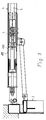
- a drive device shown in FIG. 1 for a door leaf 2 that can be moved back and forth along guide rails between an open position and a closed position consists of a drive motor (not shown), on the output shaft of which a gear is flanged, which is connected to a traction mechanism 3 designed as a toothed belt is.
- the traction means 3 is arranged in a drive guide rail 4 and guided over a deflection roller 5 held in the drive guide rail 4.
- the deflection roller 5 is arranged between two legs of a holding element 6 which is U-shaped in cross section and which has a screw bolt 7 on the end face the drive guide rail 4 is fastened with the interposition of a spring 8.
- the tension of the traction means 3 in the drive guide rail 4 is set via the spring 8 or the nut 9 screwed onto the screw bolt 7.
- the drive guide rail 4 has a U-shaped cross section and is open at the bottom. As a result, the two legs 10 of the drive guide rail 4 run essentially perpendicular.
- the drive guide rail 4 is connected on the one hand to a frame 11, in which the door leaf 2 is also arranged and which is connected to a masonry 12, not shown.
- the drive guide rail 4, preferably in the area of the drive motor, not shown, is connected to a ceiling, not shown, of the building, for example a garage.
- a driver 13 is guided, which is connected to a run of the traction means 3, so that the driver 13 can be moved together with the traction means 3 along the drive guide rail 4 in accordance with the direction of rotation of the drive motor, not shown.
- the driver 13 has at one end a vertically aligned plate 14 which has a bore 15 through which a fastening element, for example a bolt or a rivet, is inserted.
- the leg 17 is pivotally connected to a bracket 19 which is fixed to the upper edge, namely the frame 20 of the door leaf 2.
- the toggle lever 16 is described in more detail below with reference to FIG. 2.
- Each leg 17 or 18 of the toggle lever 16 is designed as a plate-shaped element and has a bore 21, 22 and 23, respectively, at its ends, the two legs in the region of the bore 22 via a connecting element, not shown, for example a bolt are interconnected. It can be seen from FIG. 2 that the length of the leg 17 is a multiple of the length of the leg 18. As already stated, the leg 17 is articulated with its end opposite the bore 22 to the bracket 19, whereas the leg 18 is connected with its end opposite the bore 22 to the plate 14 of the driver 13.
- the leg 18 has a latching element 24 designed as a hook nose, which can be connected to a latching device 25 (FIG. 1) arranged in the area of the drive guide rail 4.
- the locking device 25 is designed as a web which is fastened to both legs 10 of the drive guide rail 4, so that the locking device 25 designed as a web spans the space between the two legs 10 of the drive guide rail 4.
- the latching device 25 which is designed as a web, is adjustably fastened.
- the latching element 24 has an essentially planar latching surface 26 facing the bore 23 of the leg 18 or the driver 13 and a sliding surface 27 arranged opposite the latching surface 26, which is rounded off at least in partial areas, so that the latching element 24 when the door leaf 2 is transferred in the closed position, as shown in Figure 1, slips over the locking device 25 and then locked behind the locking device 25.
- the toggle lever 16 When the door leaf 2 is transferred from the open position into the closed position shown in FIG. 1, the toggle lever 16 is transferred from an approximately extended position into the bent position shown in FIG. 1 and in FIG. 2, which is caused by a pressure load due to the returning driver 13 .
- the toggle lever 16 In the position shown in Figures 1 and 2, the toggle lever 16 is designed as a pressure rod, so that the force acting on the toggle lever 16 is transmitted to the door leaf 2.
- the toggle lever 16 is then again moved into its approximately extended position so that it slides past beneath the locking device 25 before it then assumes its bent position behind the locking device 25, in which it locks with the locking device 25.
- a plate 29 which is arranged on the leg 18 and which represents a stop device which, in the approximately extended position of the toggle lever 16, on the narrow side or the upper edge 30 of the leg comes to rest.
- the stop device designed as a plate 29 is thus fastened in the area of the locking element 24 and limits the pivoting mobility of the two legs 17 and 18 such that a maximum angle of 179 ° between the legs 17 and 18 can be assumed.
- this angle is dimensioned such that the knee lever 16 is bent in the joint in the region of the bore 22 by an angle sufficient for the desired locking between the locking element 24 and the locking device 25 by the closing movement of the driver 13 achieve.
- the toggle lever 16 is blocked in the region of the joint in the bore 22 in such a way that the toggle lever 16 is prevented from kinking in the longitudinal direction of the plate 14 of the driver 13.
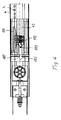
- the embodiment shown in Figures 3 and 4 differs from that of Figures 1 and 2 only in the area of the driver and the coupling element, which is not designed here as a toggle lever, but as a simple articulated lever connection between the door leaf 2 and the driver 13.
- the driver 13 is provided with a locking pawl 100 which is controlled by a spring-loaded slide 102 such that the displacement movement of the slide 102, which is approximately perpendicular to the drive movement direction of the driver 13, is transmitted to a rounded region of the locking pawl 100 in such a way that the latter is one Axis 103 pivoted when the slide moves.
- the pawl 100 engages behind an opening in a latching device 125, which is designed here as a wall within the guide rail 4.
- the slider 102 is moved against the force of a spring into the position which corresponds to the engagement of the engaging device from the latch 100 and the latching device 125, ie in this position an opening in the opening direction is exerted on the closed door leaf and via the coupling element in the Driver 13 introduced force absorbed by the latching pawl engaging in the latching device 125, so that the driver 13 cannot be displaced relative to the guide rail 4.
- a coupling 101 with a recess is fastened to the traction means 3, which is also designed here as a toothed belt, into which the slide 102 and another spring-loaded similar sliding element engage. The latter sliding element serves to completely separate the driver 13 from the traction means 3 in the event of a drive failure.
- the slider 102 is provided with a surface extending obliquely to the direction of movement of the coupling 101, such that when the traction means 3 moves in the opening direction, the coupling 101 engages with an opening edge on the inclined surface of the slider 102 and displaces it against the force of the associated spring, whereby the pawl 100 rotates about its axis 103 and thus gets outside the rear grip with the opening of the locking device 125.
- the clutch 101 takes the driver 13 with it in the direction of the door leaf opening movement, as a result of which the latch comes out of the area of the opening of the latching device 125.
- the slide 102 When moving into the closed position of the door leaf, the slide 102 is released by the clutch 101 in such a way that it enters the recess in the clutch and thus pivots the detent pawl preparatively into the engagement position.
- the pawl When the closed position is reached, the pawl is pivoted about its axis 103 against the spring force of the slide 102 by its pawl nose penetrating the opening of the latching device 125 and in the closed end position under the force of this spring moves into the coupling position, as can be seen in the sectional drawing.
Landscapes
- Power-Operated Mechanisms For Wings (AREA)
Applications Claiming Priority (2)
| Application Number | Priority Date | Filing Date | Title |
|---|---|---|---|
| DE19518493A DE19518493C2 (de) | 1995-05-19 | 1995-05-19 | Antriebseinrichtung für ein Torblatt |
| DE19518493 | 1995-05-19 |
Publications (1)
| Publication Number | Publication Date |
|---|---|
| EP0743416A1 true EP0743416A1 (fr) | 1996-11-20 |
Family
ID=7762403
Family Applications (1)
| Application Number | Title | Priority Date | Filing Date |
|---|---|---|---|
| EP96108031A Ceased EP0743416A1 (fr) | 1995-05-19 | 1996-05-20 | Dispositif d'entraînement pour un panneau de porte |
Country Status (2)
| Country | Link |
|---|---|
| EP (1) | EP0743416A1 (fr) |
| DE (1) | DE19518493C2 (fr) |
Cited By (8)
| Publication number | Priority date | Publication date | Assignee | Title |
|---|---|---|---|---|
| EP0936337A1 (fr) * | 1998-02-10 | 1999-08-18 | Robert Bosch Gmbh | Dispositif de renvoi et de tension pour une chaíne d'entraínement d'une commande d'une porte de garage |
| WO2000079086A1 (fr) | 1999-06-22 | 2000-12-28 | Hörmann KG Antriebstechnik | Dispositif de blocage et dispositif d'entrainement de porte pourvu d'un tel dispositif de blocage et destine a une porte entrainee par un groupe moteur |
| DE19951289A1 (de) * | 1999-06-22 | 2001-01-04 | Hoermann Kg Antriebstechnik | Sperrvorrichtung und damit versehene Torantriebsvorrichtung für ein mittels eines Motorantriebsaggregats antreibbares Tor |
| EP1681414A2 (fr) | 2005-01-14 | 2006-07-19 | GEZE GmbH | Dispositif de verrouillage |
| DE102007025723B3 (de) * | 2007-06-01 | 2008-09-04 | Novoferm Tormatic Gmbh | Kupplungseinheit für ein Garagentor, insbesondere Kipp-, Schwenk- oder Sektionaltor |
| EP2025853A3 (fr) * | 2007-07-02 | 2009-04-29 | Hörmann KG Antriebstechnik | Dispositif d'entraîneur pour un dispositif d'entraînement de porte, un tel dispositif d'entraînement de porte et une porte |
| FR2949497A1 (fr) * | 2009-08-31 | 2011-03-04 | Somfy Sas | Dispositif de verrouillage-deverrouillage d'une porte de garage ou analogue |
| EP2343430A1 (fr) | 2010-01-12 | 2011-07-13 | Somfy SAS | Installation de porte de garage avec actionneur et chariot mobile |
Families Citing this family (3)
| Publication number | Priority date | Publication date | Assignee | Title |
|---|---|---|---|---|
| DE10228156B4 (de) * | 2002-06-24 | 2006-10-05 | Berner Torantriebe Gmbh | Notentriegelung mit Verriegelung |
| DE102013016812B4 (de) | 2013-10-10 | 2021-12-30 | Marantec Antriebs- Und Steuerungstechnik Gmbh & Co. Kg | Aufschiebesicherung |
| DE102013017335B4 (de) * | 2013-10-17 | 2017-03-09 | Marantec Antriebs- Und Steuerungstechnik Gmbh & Co. Kg | Aufschiebesicherungsanordnung |
Citations (3)
| Publication number | Priority date | Publication date | Assignee | Title |
|---|---|---|---|---|
| US3909980A (en) * | 1974-05-16 | 1975-10-07 | Crane Co H W | Door operating mechanism |
| FR2349014A1 (fr) * | 1976-04-23 | 1977-11-18 | Roi Rene | Dispositif de verrouillage et de deverrouillage de portes basculantes a commande electrique |
| DE8802127U1 (de) * | 1988-02-18 | 1988-07-21 | Visual Communications Ingenieurberatungs GmbH, 8000 München | Einbruchsicherungsvorrichtung, insbesondere für ein Garagentor |
Family Cites Families (2)
| Publication number | Priority date | Publication date | Assignee | Title |
|---|---|---|---|---|
| DE1961916U (de) * | 1967-03-31 | 1967-06-08 | W U H Neukircher O H G | Oeffner fuer kipptore. |
| US3704548A (en) * | 1971-04-26 | 1972-12-05 | Celotex Corp | Safety door latch |
-
1995
- 1995-05-19 DE DE19518493A patent/DE19518493C2/de not_active Expired - Fee Related
-
1996
- 1996-05-20 EP EP96108031A patent/EP0743416A1/fr not_active Ceased
Patent Citations (3)
| Publication number | Priority date | Publication date | Assignee | Title |
|---|---|---|---|---|
| US3909980A (en) * | 1974-05-16 | 1975-10-07 | Crane Co H W | Door operating mechanism |
| FR2349014A1 (fr) * | 1976-04-23 | 1977-11-18 | Roi Rene | Dispositif de verrouillage et de deverrouillage de portes basculantes a commande electrique |
| DE8802127U1 (de) * | 1988-02-18 | 1988-07-21 | Visual Communications Ingenieurberatungs GmbH, 8000 München | Einbruchsicherungsvorrichtung, insbesondere für ein Garagentor |
Cited By (12)
| Publication number | Priority date | Publication date | Assignee | Title |
|---|---|---|---|---|
| EP0936337A1 (fr) * | 1998-02-10 | 1999-08-18 | Robert Bosch Gmbh | Dispositif de renvoi et de tension pour une chaíne d'entraínement d'une commande d'une porte de garage |
| WO2000079086A1 (fr) | 1999-06-22 | 2000-12-28 | Hörmann KG Antriebstechnik | Dispositif de blocage et dispositif d'entrainement de porte pourvu d'un tel dispositif de blocage et destine a une porte entrainee par un groupe moteur |
| DE19951289A1 (de) * | 1999-06-22 | 2001-01-04 | Hoermann Kg Antriebstechnik | Sperrvorrichtung und damit versehene Torantriebsvorrichtung für ein mittels eines Motorantriebsaggregats antreibbares Tor |
| DE19951289C2 (de) * | 1999-06-22 | 2001-06-13 | Hoermann Kg Antriebstechnik | Sperrvorrichtung und damit versehene Torantriebsvorrichtung für ein mittels eines Motorantriebsaggregats antreibbares Tor |
| EP1681414A2 (fr) | 2005-01-14 | 2006-07-19 | GEZE GmbH | Dispositif de verrouillage |
| EP1681414A3 (fr) * | 2005-01-14 | 2012-07-18 | GEZE GmbH | Dispositif de verrouillage |
| DE102007025723B3 (de) * | 2007-06-01 | 2008-09-04 | Novoferm Tormatic Gmbh | Kupplungseinheit für ein Garagentor, insbesondere Kipp-, Schwenk- oder Sektionaltor |
| EP2025853A3 (fr) * | 2007-07-02 | 2009-04-29 | Hörmann KG Antriebstechnik | Dispositif d'entraîneur pour un dispositif d'entraînement de porte, un tel dispositif d'entraînement de porte et une porte |
| FR2949497A1 (fr) * | 2009-08-31 | 2011-03-04 | Somfy Sas | Dispositif de verrouillage-deverrouillage d'une porte de garage ou analogue |
| EP2299039A1 (fr) * | 2009-08-31 | 2011-03-23 | Somfy SAS | Dispositif de verrouillage-deverrouillage d'une porte de garage ou analogue |
| EP2343430A1 (fr) | 2010-01-12 | 2011-07-13 | Somfy SAS | Installation de porte de garage avec actionneur et chariot mobile |
| FR2955140A1 (fr) * | 2010-01-12 | 2011-07-15 | Somfy Sas | Installation de porte de garage avec actionneur et chariot mobile |
Also Published As
| Publication number | Publication date |
|---|---|
| DE19518493A1 (de) | 1996-11-21 |
| DE19518493C2 (de) | 1999-09-02 |
Similar Documents
| Publication | Publication Date | Title |
|---|---|---|
| EP3702562B1 (fr) | Ferrure de fixation ainsi qu'agencement de ferrure et agencement de cadre et de battant | |
| DE19920511A1 (de) | Türinnengriff für Automobile | |
| DE8909801U1 (de) | Treibstangenschloß | |
| EP0119433B2 (fr) | Ferrure pour un panneau de fenêtre, de porte ou similaire, pouvant au moins basculer et se déplacer d'un plan dans un deuxième plan parallèle | |
| EP1187963B1 (fr) | Dispositif de blocage et dispositif d'entrainement de porte pourvu d'un tel dispositif de blocage et destine a une porte entrainee par un groupe moteur | |
| EP0743416A1 (fr) | Dispositif d'entraînement pour un panneau de porte | |
| EP0678639B1 (fr) | Dispositif de verrouillage pour volets, portes et éléments similaires mobiles sur un rail fixe | |
| DE19951289C2 (de) | Sperrvorrichtung und damit versehene Torantriebsvorrichtung für ein mittels eines Motorantriebsaggregats antreibbares Tor | |
| WO2023143824A1 (fr) | Dispositif de décalage pour le décalage forcé d'un vantail, en particulier d'un vantail coulissant, d'une fenêtre ou d'une porte | |
| EP0509137A1 (fr) | Dispositif de sellette d'attelage mot clef: poignée de manoeuvre | |
| DE3520861A1 (de) | Rueckdruecksperre an treibstangenbeschlaegen, insbesondere schluesselbetaetigbaren treibstangenschloessern | |
| DE102020111221A1 (de) | Laufwagenanordnung für eine Schiebetür | |
| DE19628011C2 (de) | Spereinrichtung für die Riegel eine Riegelwerks | |
| EP0197025B1 (fr) | Dispositif à actionner en cas de danger pour verrouillages de portes sans poignée | |
| EP0846825B1 (fr) | Dispositif de verrouillage pour un vantail de porte amovible dans un châssis | |
| EP1514985A2 (fr) | Dispositif de verrouillage pour portes de véhicules, notamment portes pivotantes-coulissantes pour un véhicule ferroviaire | |
| DE29512996U1 (de) | Vorrichtung zum Schließen und Verriegeln von Fensterflügeln o.dgl. | |
| DE29808661U1 (de) | Sicherungsvorrichtung für mittels Tragseil hebbare Tore | |
| EP0752328B1 (fr) | Attelage de remorque | |
| DE29508387U1 (de) | Antriebseinrichtung für ein Torblatt | |
| EP1746235B1 (fr) | Ensemble de ferrure | |
| EP0790375A2 (fr) | Fenêtre ou porte-fenêtre avec ferrure pour ouvrant pivotant ou ouvrant oscillo-battant | |
| DE4406870C1 (de) | Kraftfahrzeug-Türschloß | |
| DE3707324A1 (de) | Tuerverriegelungssystem | |
| EP0518099B1 (fr) | Dispositif pour ouvrir et fermer une porte basculante |
Legal Events
| Date | Code | Title | Description |
|---|---|---|---|
| PUAI | Public reference made under article 153(3) epc to a published international application that has entered the european phase |
Free format text: ORIGINAL CODE: 0009012 |
|
| AK | Designated contracting states |
Kind code of ref document: A1 Designated state(s): AT BE CH DE DK ES FR GB IT LI NL SE |
|
| 17P | Request for examination filed |
Effective date: 19970516 |
|
| 17Q | First examination report despatched |
Effective date: 19970623 |
|
| RAP1 | Party data changed (applicant data changed or rights of an application transferred) |
Owner name: HOERMANN KG ANTRIEBSTECHNIK |
|
| GRAG | Despatch of communication of intention to grant |
Free format text: ORIGINAL CODE: EPIDOS AGRA |
|
| STAA | Information on the status of an ep patent application or granted ep patent |
Free format text: STATUS: THE APPLICATION HAS BEEN REFUSED |
|
| 18R | Application refused |
Effective date: 20000421 |