EP0743472A2 - Couche pour éléments à paliers pour engrenage planétaire et son procédé de préparation - Google Patents
Couche pour éléments à paliers pour engrenage planétaire et son procédé de préparation Download PDFInfo
- Publication number
- EP0743472A2 EP0743472A2 EP96303439A EP96303439A EP0743472A2 EP 0743472 A2 EP0743472 A2 EP 0743472A2 EP 96303439 A EP96303439 A EP 96303439A EP 96303439 A EP96303439 A EP 96303439A EP 0743472 A2 EP0743472 A2 EP 0743472A2
- Authority
- EP
- European Patent Office
- Prior art keywords
- gear
- planet
- bearing
- coating
- bearing material
- Prior art date
- Legal status (The legal status is an assumption and is not a legal conclusion. Google has not performed a legal analysis and makes no representation as to the accuracy of the status listed.)
- Ceased
Links
- 238000000034 method Methods 0.000 title claims abstract description 31
- 230000008569 process Effects 0.000 title abstract description 22
- 239000000463 material Substances 0.000 claims abstract description 51
- 238000000576 coating method Methods 0.000 claims abstract description 46
- 239000011248 coating agent Substances 0.000 claims abstract description 42
- 239000000203 mixture Substances 0.000 claims abstract description 20
- 238000004544 sputter deposition Methods 0.000 claims abstract description 18
- 238000007740 vapor deposition Methods 0.000 claims abstract 2
- RYGMFSIKBFXOCR-UHFFFAOYSA-N Copper Chemical compound [Cu] RYGMFSIKBFXOCR-UHFFFAOYSA-N 0.000 claims description 8
- 229910052802 copper Inorganic materials 0.000 claims description 8
- 239000010949 copper Substances 0.000 claims description 8
- ATJFFYVFTNAWJD-UHFFFAOYSA-N Tin Chemical compound [Sn] ATJFFYVFTNAWJD-UHFFFAOYSA-N 0.000 claims description 4
- 229910052709 silver Inorganic materials 0.000 claims description 4
- 229910052718 tin Inorganic materials 0.000 claims description 4
- BQCADISMDOOEFD-UHFFFAOYSA-N Silver Chemical compound [Ag] BQCADISMDOOEFD-UHFFFAOYSA-N 0.000 claims description 3
- 239000004332 silver Substances 0.000 claims description 3
- 229910052782 aluminium Inorganic materials 0.000 claims description 2
- XAGFODPZIPBFFR-UHFFFAOYSA-N aluminium Chemical compound [Al] XAGFODPZIPBFFR-UHFFFAOYSA-N 0.000 claims description 2
- 229910052787 antimony Inorganic materials 0.000 claims description 2
- WATWJIUSRGPENY-UHFFFAOYSA-N antimony atom Chemical compound [Sb] WATWJIUSRGPENY-UHFFFAOYSA-N 0.000 claims description 2
- 229910052738 indium Inorganic materials 0.000 claims description 2
- APFVFJFRJDLVQX-UHFFFAOYSA-N indium atom Chemical compound [In] APFVFJFRJDLVQX-UHFFFAOYSA-N 0.000 claims description 2
- 230000008093 supporting effect Effects 0.000 claims description 2
- WIKSRXFQIZQFEH-UHFFFAOYSA-N [Cu].[Pb] Chemical compound [Cu].[Pb] WIKSRXFQIZQFEH-UHFFFAOYSA-N 0.000 abstract description 9
- 238000004519 manufacturing process Methods 0.000 abstract description 2
- 230000005540 biological transmission Effects 0.000 abstract 1
- 239000010408 film Substances 0.000 description 14
- 239000003921 oil Substances 0.000 description 11
- 238000012360 testing method Methods 0.000 description 10
- 230000001965 increasing effect Effects 0.000 description 9
- 229910045601 alloy Inorganic materials 0.000 description 8
- 239000000956 alloy Substances 0.000 description 8
- 150000002500 ions Chemical class 0.000 description 6
- 229910000978 Pb alloy Inorganic materials 0.000 description 5
- 238000010276 construction Methods 0.000 description 5
- 238000000151 deposition Methods 0.000 description 5
- 239000000758 substrate Substances 0.000 description 5
- 229910000906 Bronze Inorganic materials 0.000 description 3
- 239000010974 bronze Substances 0.000 description 3
- 150000001875 compounds Chemical class 0.000 description 3
- KUNSUQLRTQLHQQ-UHFFFAOYSA-N copper tin Chemical compound [Cu].[Sn] KUNSUQLRTQLHQQ-UHFFFAOYSA-N 0.000 description 3
- 230000008021 deposition Effects 0.000 description 3
- 230000001976 improved effect Effects 0.000 description 3
- 230000014759 maintenance of location Effects 0.000 description 3
- 229910052751 metal Inorganic materials 0.000 description 3
- 239000002184 metal Substances 0.000 description 3
- 230000000717 retained effect Effects 0.000 description 3
- 239000010409 thin film Substances 0.000 description 3
- 239000011135 tin Substances 0.000 description 3
- PXHVJJICTQNCMI-UHFFFAOYSA-N Nickel Chemical compound [Ni] PXHVJJICTQNCMI-UHFFFAOYSA-N 0.000 description 2
- 229910000831 Steel Inorganic materials 0.000 description 2
- 230000007423 decrease Effects 0.000 description 2
- 238000011161 development Methods 0.000 description 2
- 230000005684 electric field Effects 0.000 description 2
- 238000005516 engineering process Methods 0.000 description 2
- 239000007888 film coating Substances 0.000 description 2
- 238000009501 film coating Methods 0.000 description 2
- 239000012530 fluid Substances 0.000 description 2
- 230000014509 gene expression Effects 0.000 description 2
- 238000010438 heat treatment Methods 0.000 description 2
- 229910052745 lead Inorganic materials 0.000 description 2
- 239000010687 lubricating oil Substances 0.000 description 2
- 150000002739 metals Chemical class 0.000 description 2
- 238000012986 modification Methods 0.000 description 2
- 230000004048 modification Effects 0.000 description 2
- 239000002245 particle Substances 0.000 description 2
- 238000000623 plasma-assisted chemical vapour deposition Methods 0.000 description 2
- 239000010959 steel Substances 0.000 description 2
- 238000000859 sublimation Methods 0.000 description 2
- 230000008022 sublimation Effects 0.000 description 2
- 239000013077 target material Substances 0.000 description 2
- 238000005496 tempering Methods 0.000 description 2
- 208000016261 weight loss Diseases 0.000 description 2
- PWHULOQIROXLJO-UHFFFAOYSA-N Manganese Chemical compound [Mn] PWHULOQIROXLJO-UHFFFAOYSA-N 0.000 description 1
- 230000000573 anti-seizure effect Effects 0.000 description 1
- 239000001996 bearing alloy Substances 0.000 description 1
- 238000005452 bending Methods 0.000 description 1
- 230000008901 benefit Effects 0.000 description 1
- 238000005255 carburizing Methods 0.000 description 1
- 229910052729 chemical element Inorganic materials 0.000 description 1
- 238000006243 chemical reaction Methods 0.000 description 1
- 230000008878 coupling Effects 0.000 description 1
- 238000010168 coupling process Methods 0.000 description 1
- 238000005859 coupling reaction Methods 0.000 description 1
- 238000013461 design Methods 0.000 description 1
- 230000001066 destructive effect Effects 0.000 description 1
- 230000009977 dual effect Effects 0.000 description 1
- 230000005672 electromagnetic field Effects 0.000 description 1
- 238000005328 electron beam physical vapour deposition Methods 0.000 description 1
- 238000010894 electron beam technology Methods 0.000 description 1
- 230000008030 elimination Effects 0.000 description 1
- 238000003379 elimination reaction Methods 0.000 description 1
- 230000005281 excited state Effects 0.000 description 1
- 238000009472 formulation Methods 0.000 description 1
- 230000003116 impacting effect Effects 0.000 description 1
- 230000001939 inductive effect Effects 0.000 description 1
- 230000000977 initiatory effect Effects 0.000 description 1
- 239000007788 liquid Substances 0.000 description 1
- 239000000314 lubricant Substances 0.000 description 1
- 230000001050 lubricating effect Effects 0.000 description 1
- 238000005461 lubrication Methods 0.000 description 1
- 229910052748 manganese Inorganic materials 0.000 description 1
- 239000011572 manganese Substances 0.000 description 1
- 238000005259 measurement Methods 0.000 description 1
- 238000002844 melting Methods 0.000 description 1
- 230000008018 melting Effects 0.000 description 1
- 238000005272 metallurgy Methods 0.000 description 1
- 230000007935 neutral effect Effects 0.000 description 1
- 229910052759 nickel Inorganic materials 0.000 description 1
- 230000003287 optical effect Effects 0.000 description 1
- 238000005457 optimization Methods 0.000 description 1
- 239000002243 precursor Substances 0.000 description 1
- 238000012545 processing Methods 0.000 description 1
- 230000009467 reduction Effects 0.000 description 1
- 238000005204 segregation Methods 0.000 description 1
- 238000010583 slow cooling Methods 0.000 description 1
- 239000007787 solid Substances 0.000 description 1
- 210000000952 spleen Anatomy 0.000 description 1
- 239000000126 substance Substances 0.000 description 1
- 230000003746 surface roughness Effects 0.000 description 1
- 229910000597 tin-copper alloy Inorganic materials 0.000 description 1
- 239000013585 weight reducing agent Substances 0.000 description 1
Images

Classifications
-
- F—MECHANICAL ENGINEERING; LIGHTING; HEATING; WEAPONS; BLASTING
- F16—ENGINEERING ELEMENTS AND UNITS; GENERAL MEASURES FOR PRODUCING AND MAINTAINING EFFECTIVE FUNCTIONING OF MACHINES OR INSTALLATIONS; THERMAL INSULATION IN GENERAL
- F16H—GEARING
- F16H57/00—General details of gearing
- F16H57/08—General details of gearing of gearings with members having orbital motion
-
- F—MECHANICAL ENGINEERING; LIGHTING; HEATING; WEAPONS; BLASTING
- F16—ENGINEERING ELEMENTS AND UNITS; GENERAL MEASURES FOR PRODUCING AND MAINTAINING EFFECTIVE FUNCTIONING OF MACHINES OR INSTALLATIONS; THERMAL INSULATION IN GENERAL
- F16C—SHAFTS; FLEXIBLE SHAFTS; ELEMENTS OR CRANKSHAFT MECHANISMS; ROTARY BODIES OTHER THAN GEARING ELEMENTS; BEARINGS
- F16C17/00—Sliding-contact bearings for exclusively rotary movement
- F16C17/02—Sliding-contact bearings for exclusively rotary movement for radial load only
-
- F—MECHANICAL ENGINEERING; LIGHTING; HEATING; WEAPONS; BLASTING
- F16—ENGINEERING ELEMENTS AND UNITS; GENERAL MEASURES FOR PRODUCING AND MAINTAINING EFFECTIVE FUNCTIONING OF MACHINES OR INSTALLATIONS; THERMAL INSULATION IN GENERAL
- F16C—SHAFTS; FLEXIBLE SHAFTS; ELEMENTS OR CRANKSHAFT MECHANISMS; ROTARY BODIES OTHER THAN GEARING ELEMENTS; BEARINGS
- F16C33/00—Parts of bearings; Special methods for making bearings or parts thereof
- F16C33/02—Parts of sliding-contact bearings
- F16C33/04—Brasses; Bushes; Linings
- F16C33/06—Sliding surface mainly made of metal
- F16C33/08—Attachment of brasses, bushes or linings to the bearing housing
-
- F—MECHANICAL ENGINEERING; LIGHTING; HEATING; WEAPONS; BLASTING
- F16—ENGINEERING ELEMENTS AND UNITS; GENERAL MEASURES FOR PRODUCING AND MAINTAINING EFFECTIVE FUNCTIONING OF MACHINES OR INSTALLATIONS; THERMAL INSULATION IN GENERAL
- F16C—SHAFTS; FLEXIBLE SHAFTS; ELEMENTS OR CRANKSHAFT MECHANISMS; ROTARY BODIES OTHER THAN GEARING ELEMENTS; BEARINGS
- F16C33/00—Parts of bearings; Special methods for making bearings or parts thereof
- F16C33/02—Parts of sliding-contact bearings
- F16C33/04—Brasses; Bushes; Linings
- F16C33/06—Sliding surface mainly made of metal
- F16C33/12—Structural composition; Use of special materials or surface treatments, e.g. for rust-proofing
- F16C33/121—Use of special materials
-
- F—MECHANICAL ENGINEERING; LIGHTING; HEATING; WEAPONS; BLASTING
- F16—ENGINEERING ELEMENTS AND UNITS; GENERAL MEASURES FOR PRODUCING AND MAINTAINING EFFECTIVE FUNCTIONING OF MACHINES OR INSTALLATIONS; THERMAL INSULATION IN GENERAL
- F16C—SHAFTS; FLEXIBLE SHAFTS; ELEMENTS OR CRANKSHAFT MECHANISMS; ROTARY BODIES OTHER THAN GEARING ELEMENTS; BEARINGS
- F16C33/00—Parts of bearings; Special methods for making bearings or parts thereof
- F16C33/02—Parts of sliding-contact bearings
- F16C33/04—Brasses; Bushes; Linings
- F16C33/06—Sliding surface mainly made of metal
- F16C33/14—Special methods of manufacture; Running-in
-
- Y—GENERAL TAGGING OF NEW TECHNOLOGICAL DEVELOPMENTS; GENERAL TAGGING OF CROSS-SECTIONAL TECHNOLOGIES SPANNING OVER SEVERAL SECTIONS OF THE IPC; TECHNICAL SUBJECTS COVERED BY FORMER USPC CROSS-REFERENCE ART COLLECTIONS [XRACs] AND DIGESTS
- Y10—TECHNICAL SUBJECTS COVERED BY FORMER USPC
- Y10S—TECHNICAL SUBJECTS COVERED BY FORMER USPC CROSS-REFERENCE ART COLLECTIONS [XRACs] AND DIGESTS
- Y10S384/00—Bearings
- Y10S384/90—Cooling or heating
- Y10S384/912—Metallic
Definitions
- the invention relates to planet gears having bearing materials coated directly onto the inner bore surface of the gears and methods for producing the same.
- Speed reducing planetary gear systems have been used for aircraft propulsion systems in either the dual output shaft mode, in which power is extracted from both the planet gear carrier and the ring gear, rotating in opposite directions, or the single output mode, in which either the ring gear or the planet carrier is fixed to the engine frame.
- the low pressure turbine shaft rotating at high speed, typically directly drives the sun gear of a planetary gear system.
- This gear system includes a planet gear carrier supporting a plurality of planet gears and transferring power and load from the sun gear through the planet gears to one or both output shafts. High speeds and loads are imposed on this gear system, increasing with aircraft propulsion power requirements.
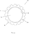
- FIG. 1 illustrates a prior planetary gear system.
- the prior art planetary gear assembly 10 includes a ring gear 12 which is rigidly supported on support 14.
- Sun gear 16 is centrally located within the ring gear.
- Five planet gears 18 are arranged to mesh with the sun gear 16 and ring gear 12.
- Each planet gear 18 has an outer gear section 20 with a bearing sleeve 22 fitted inside.
- the planet gear is supported on pin 24 which in turn is supported by the planet gear carrier 26.
- Sun gear 16 is rotated in the direction 28 applying force 30 against the planet gear 18. This causes the planet gear to rotate in the direction of arrow 32 because of the force 34 imposed by the ring gear 12. The planet gears 18 and the planet gear carrier 26 move in the direction 36.
- Centrifugal force imposes a G-force 38 on the planet gear.
- the combination of these forces results in a resultant force 40 transferred from the planet gear bearing 22 through a lubricating oil film to the pin 24, and thence to the carrier 26.
- Previous gear systems employed steel-backed cast leaded bronze sleeves (item 22 in Figure 1) installed in the planet gears with a very tight shrink fit.
- the sleeve 22 rotates around the pin 24.
- the cast leaded bronze bore of the sleeve acts as the journal bearing surface. Deflection of the pin, the carrier or the planet gear leads to distortion of the bearing surface and to localized variations in the bearing clearance.
- a balance is required between a minimum clearance and excessive clearance in order for the bearing to function properly. Too small a clearance results in excessive lubricant film temperature, and too large a clearance will result in inadequate film thickness.
- the load on the planet bearing which must be transferred through the pin to the carrier includes the sun gear force plus the ring gear force and the G-field centrifugal force due to planet gear mass.
- a larger pin would stiffen the pin surface and lead to lower planet weight and also lower G-forces, but in turn increase planet distortion. It would also stiffen the carrier assembly and diminish load sharing capability between the various planet gears.
- a smaller diameter pin would facilitate load sharing but increases planet G-forces bending of the pin.
- the prior art bearing sleeves have to be fabricated separately, assembled into the planet gear, retained mechanically with suitable features, and machine finished. These sleeves also add weight and cost to the prior art planetary gear systems. Furthermore, the separate steel backed bearing sleeve found in previous gear systems requires increasingly tighter shrink fit with the planet gear as gear distortion increases with increasing mesh loads, G-Forces and/or gear flexibility.
- the present invention overcomes these disadvantages by providing an integral one-piece construction of a planet gear having a bearing coating directly applied to the inner bore surface of the gear.
- United States Patent No. 5,102,379 to Pagluica et al. discloses a planetary gear system which includes a plurality of planet gears, each having a journal bearing and a pin (see abstract).
- the journal bearing In Pagluica et al., the journal bearing must be fabricated separately, inserted into the planet gear and machine finished. This adds additional weight and costs, while reducing reliability.
- the present invention combines gear and journal bearing mechanical elements into a single precision part produced by directly coating the inner bore of the gear with a bearing material.
- This invention eliminates the need for a bearing sleeve which has to be fabricated separately, assembled into the gear, retained mechanically with suitable features, and machine finished.
- This invention provides an integral one-piece construction for reduced weight and cost, increased load capacity and precision, which eliminates risk of failure of any mechanical retention features.
- a planetary gear assembly generally contains a plurality of planet gears which are supported on a planet carrier and located between a sun gear and a ring gear.
- Each of the planet gears typically has the shape of a thick cylinder with teeth on the outer diameter thereof and a smooth inner bore surface.
- the inner bore surface is coated with a bearing material.
- the invention eliminates the use of a bearing sleeve which has to be fabricated separately, assembled into the gear bore, retained mechanically with suitable features and machine finished. Since such sleeves add weight without adding strength, elimination of the sleeves increases the strength to weight ratio of the planet gear.
- This invention provides an integral one-piece construction for reduced weight and cost, while at the same time increasing load capacity and precision.
- the invention eliminates the risk of failure of any mechanical retention feature (i.e., interference fit, key, spleen, shoulder, etc.). Testing has shown that the sputtered layer not only reduces size and weight, but also increases load capacity and reliability.
- the coating material must be applied following elevated temperature heat treatment steps of the gear teeth, such as carburizing, hardening or tempering, since these processes are carried out at temperatures damaging or destructive to the bearing coating.
- the coating material on the one hand, must be applied at temperatures low enough to avoid further tempering of the gear teeth.
- Using a sputtering process for coating provides a finely dispersed mixture of material alloy elements whether or not such elements are readily combined using alternative coating methods.
- the optimum sputtered layer is 0.0016 to 0.0040 inches, preferably only 0.0030 to 0.0032 inches thick. This is about one-tenth the thickness of the prior cast leaded bronze layers used as sleeves. The thickness should be uniform within plus or minus 50 micro inches.
- the hardness of the bearing' material should be about 120-170 Vickers, preferably 130-150.
- the surface finish should be about 10-50 micro-inches AA, preferably about 20 micro-inches.
- the preferred bearing material composition for the power gear application is a mixture of copper and lead, with a lead content between 20 and 30% by volume, preferably between 25 and 29%.
- a p-v level (pressure x velocity) is a wear factor used for evaluating gear systems.
- the p-v level achieved using the planet gear coated with a bearing material according to the present invention is at least as high as a system using a bearing sleeve.
- the p-v level for the present invention is up to 17.7 x 10 6 PSI.FT/MIN.
- the gear having a bearing coating in accordance with the teachings of the present invention achieves significantly lower Sommerfeld numbers.
- the Sommerfeld number is a nondimensional number used to characterize the performance of journal bearings.
- the Sommerfeld number is proportional to viscosity and speed and inversely proportional to load and clearance. For high loads and small bearing support areas, the unit load increases and lower Sommerfeld numbers are required. When the temperature of the planetary gear system increases during use, the viscosity decreases and lower Sommerfeld numbers are required.
- the present invention allows the gear system to operate at lower Sommerfeld number ranges than with the prior bearing sleeves down to about 0.0008.
- bearing coating can be refurbished with additional applications of the bearing material.
- the performance of refurbished bearings was found to be equivalent to that of new bearings.
- the present invention therefore, achieves surprising results with a reduction of weight and cost.
- the bearing coating eliminates the bearing sleeve, without sacrificing performance.
- the planet gear according to the present invention comprises a bearing material coated directly onto the inner bore surface.
- the planetary gear systems of the prior art include a plurality of planet gears, each having a journal bearing sleeve inserted into the gear bore and a pin.
- the present invention replaces the bearing sleeve with a coating which is applied directly to the inner surface of the planet gear.
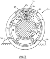
- each planet gear 48 in accordance with the teachings of the present invention has a gear rim section 49 with a bearing material 50 coated onto the inner bore surface.
- Gear teeth 51 are located on the outer surface of the gear and the gear 48 is supported on pin 52.
- An oil film is located at the interface 53 of the bearing material 50 and the pin 52.
- the coated gear is one of several disposed around a central externally toothed "sun” gear and a concentric internally toothed “ring” gear. Each planet gear meshes with both the sun and the ring gear.
- the subject gear (known as a “planet” or “star” gear) is positioned by and loaded against a radial or “journal” fluid film bearing.
- the cylindrical inner surface of the gear (or outer boundary of the load carrying fluid film) is coated with a suitable wear resistant metallic layer of "bearing material".
- a layer of bearing material of suitable thickness is applied directly to the inner surface of the gear.
- a planetary gear assembly 54 includes a ring gear 55 which is rigidly supported on support 56. Sun gear 57 is centrally located within the ring gear 55. Five planet gears 48 are arranged to mesh with both the sun gear 57 and the ring gear 55.
- Each planet gear 48 has a gear rim section 41 with bearing material 50 coated onto the inner bore surface thereof.
- the gear 48 is supported on pin 52 which in turn is then supported by the planet gear carrier 58.
- Gear teeth 51 are located between the sun gear and the planet gear 48.
- Planet bearing material 50 is coated within the internal circumference of the planet gear.
- the sun gear 57 is rotated in the direction of arrow 59 which applies force 60 against the planet gear.
- the planet gears 48 and the planet gear carrier 58 thus move in the direction of arrow 64.
- Centrifugal force imposes a G-force 65 on the planet gear.
- the combination of these forces results in a resultant force 66 transferred from the planet gear bearing coating 50 through a lubricating oil film to the pin 52, and thence to the carrier 58.
- the lubricating film of oil supplied by pressure fed oil through holes in the pin, transfers load and prevents wear of the coating and pin surfaces.
- the oil film is located at the interface 53 of the bearing coating and the pin 52.
- the pin geometry has been optimized in conjunction with the gear system flexibility and bearing clearance variations to insure a uniform pressure profile within the bearing oil film at the bearing/pin interface 53.
- the coating should be applied to the gear following all metallurgical processing (heat treatment) of the gear material to avoid damage to the coating. Furthermore, the coating application process should be accomplished at temperatures below those which might alter the metallurgy of the gear.
- the coating methods that can be used to coat a bearing material on the surface of gear include: (1) sputtering or analogous thermal sublimation; (2) electron beam physical vapor deposition; or (3) plasma deposition, and combination of these processes.
- the development of technology relating to the coating of various materials has been escalating in recent years. Both the biomedical and electronics field have been involved in the technology because films have great utility in these areas.
- a sputtering process which transfers atomic level particles of bearing alloy elements to the internal surface of the gear has been found effective.
- the sputtering process impinges high velocity electrons on a target comprising the material to be transferred to the bearing surface, releasing electrically charged ions of the target material elements. These ions are transferred and deposited through controlled voltage potential and temperature of the bearing surface.
- Both sputtering or analogous thermal sublimation systems take a compound and bombard it with ions which have been accelerated towards the coating material by a high radio frequency or direct current potential.
- the momentum of the impacting ions transfers energy to the solids surface atoms causing them to be ejected at high velocities onto a substrate surface.
- the electron beam process imparts ample energy to sublime the substrate in a vacuum.
- the energy levels of the e-beam must be ⁇ 20-40 kilowatts per gun thus requiring nuclear x-ray shielding.
- Plasma enhanced chemical vapor deposition is activated by means of electromagnetic energy which must be sufficient so that the gas or liquid separates into electrons, ions, and free radicals and other excited state species.
- the coating compound is vaporized and introduced into a vacuum chamber where it is subjected to an electronic discharge.
- the electromagnetic field causes electrons to be ejected, creating ions and initiating a chain reaction to generate more charged particles.
- the excited species of gas in the glowing plasma are attracted to the substrate surface.
- the excited and neutral species of the compound are deposited on the substrate surface and built up atom by atom until a continuous layer is formed.
- a thin film depositing plasma is formed in a chamber by introducing at least one gaseous precursor into a region having a controlled electrical field.
- the process parameters that are usually controlled during plasma deposition include the internal pressure level, the electrical field characteristics, the composition of the gas, its flow rate into the plasma and the target-bearing spacing. Varying these parameters will vary the characteristics and properties of the resultant film. It is, of course, desired to control these plasma variables to produce a film coating having the desired film properties. As applied to the present invention, it would be desirable to adjust the parameters to result in a film coating having a uniform thickness and composition.
- One method involves a process of depositing a thin film onto a surface of a substrate with the use of a plasma, wherein the plasma optical emission is monitored, analyzed and the results used to automatically control the nature of the plasma in order to control the characteristics of the deposited thin film.
- the frequencies typically used in chemical plasma depositions range from about 10 KHz to about 1 GHz, and pressures vary from about 0.00001 to about 50 torr.
- the power coupling can be capacitive, inductive or microwave.
- Microwave plasma enhanced chemical vapor deposition uses microwave energy in addition to the above process. This creates a similar product as described above.
- the preferred method of coating the bearing material into the gear bore is sputtering.
- the main advantage of the sputtering process is that it produces a finely dispersed, uniform mixture of material alloy elements.
- the sputtering process has been continuously improved and developed over the last 15 years in the electronic and biomedical fields. Recent testing has confirmed that sputtering produces coatings with uniform thickness and ideal microstructure for application to highly loaded planetary gear systems.
- the bearing material shall comprise two or more chemical elements.
- the principal component is preferably a metal with high thermal conductivity and suitable strength, hardness and melting point.
- the preferred metals for the principal component include copper, aluminum or silver.
- the secondary components are used to impart suitable anti-friction and wear-resistant properties to the exposed surface.
- the preferred metals for the secondary components include lead, tin, indium and antimony.
- the bearing material is preferably a copper-lead alloy. Copper-lead alloys have been used extensively in the automotive and aircraft industries. These alloys have been used in steel-backed bearings. In general engineering, copper-lead alloys have found wide application as bearings and bushings. The hardness and compressive and tensile strengths of these alloys decrease as the lead content is increased.
- the preferred bearing material composition for the power gear application is a mixture of copper and lead, with a lead content between 20 and 30% by volume, preferably between 25 and 29% by volume.
- Copper-lead alloys containing about 30% Pb and as much as 5% Ag have been used.
- Another type of bearing which has been used has an intermediate layer of 25% Pb copper-lead cast on a shell back and a thin plated overlay of lead-tin-copper alloy. These alloys have exceptionally high resistance to fatigue and are widely used in the automotive, diesel and aircraft fields.
- the composition of the bearing material must be carefully optimized to achieve the desired characteristics for fatigue strength, heat transfers, lubricity and wear resistance.
- Silver and tin may be substituted for part of the copper in order to increase fatigue strength.
- the coating should have a thickness ofless than about 0.0040 inches.
- the coating should have a thickness of about 0.0016 to 0.0040 inches, more preferably 0.0021 to 0.0037 inches, even more preferably 0.0026 to 0.0034 inches and most preferably 0.0030 to 0.0032 inches.
- the resultant coating of bearing material should be substantially uniform composition and thickness, preferably with a variation in thickness of less than 15%, more preferably less than 10%, even more preferably less than 3%, and most preferably less than 1%.
- a sputtering process and a bearing coating material composition have been developed for direct application of a copper-lead coating to a planetary gear bore of diameter 90 mm.
- the process and the coating were first applied to a sub-scale bushing of diameter 75 mm. to simulate planetary gear operating conditions in a development test program.
- the coated bushing was tested on a material development rig which simulates the environment the material coating will be subjected to when incorporated into a planetary gear system.
- the purpose of the rig is to test the properties of the sputtered bearing material.
- the sputtering process was conducted in a vacuum typically involving temperatures as high as 570° F.
- the target materials used were combined rings of copper and lead mounted in the center of the gear or bushing bore.
- the sputtering rate was approximately 0.05 in 3 /hr.
- Margin testing was employed in which the test program was designed to explore the operating limits of the sputtering process and the coating. Parametric ranges tested included lead content from 20 to 35%, thickness from .0016 to .0045 in., hardness from 110 to 160 MHV and surface finish from 10 to 50 micro inches.
- a coated planet gear according to the present invention and a prior art gear were tested in a gear test rig.
- the rig simulates the environment the planet gears would be subjected to when integrated into a planetary gear system.
- Full-scale component testing confirmed that a lightweight sputtered planet gear performs at least as well as the conventional cast bearing sleeved gear. This is an unexpected result given that the sputtered planet gear achieves this while at the same time reducing the weight of the system. Weight reductions of at least 25% are achievable since the sputtered planet gear is smaller than the sleeved planet gear, has a smaller gear pitch diameter and thus provides a smaller and therefore lighter gear system.
- the full-scale gear bore was sputter coated in a vacuum at temperatures up to 570°F.
- the sputtering rate was approximately 0.05 in 3 /hr.
- Component rig testing was conducted for both the conventional cast bearing sleeved gear and the sputtered gear at identical operating conditions. The success criteria was based on measurements of the journal bearing pin temperatures at normal and reduced oil flows. Results showed that specific oil flows could be reduced from levels of .20 to levels of .05 lb/min. per million lb. ft/min., without violating the temperature limits established in Example 1.
- the sputtered gear temperature was consistently lower than the conventional cast bearing sleeved gear temperature.
- oil supply temperature could be simultaneously increased by 20°F. This latter result reduces internal energy losses and directly increases the overall efficiency of the gear system.
- the present invention has great application for the formulation of improved planet gears and planetary gear systems.
- the present invention provides a planet gear with a bearing coating having an integral one-piece construction for reduced weight and cost, increased load capacity and precision.
- the invention eliminates the risk of failure of any mechanical retention features, while at the same time achieving improved PV levels and Sommerfeld numbers.
Landscapes
- Engineering & Computer Science (AREA)
- General Engineering & Computer Science (AREA)
- Mechanical Engineering (AREA)
- General Details Of Gearings (AREA)
- Sliding-Contact Bearings (AREA)
- Retarders (AREA)
Applications Claiming Priority (2)
| Application Number | Priority Date | Filing Date | Title |
|---|---|---|---|
| US08/442,619 US5685797A (en) | 1995-05-17 | 1995-05-17 | Coated planet gear journal bearing and process of making same |
| US442619 | 1995-05-17 |
Publications (2)
| Publication Number | Publication Date |
|---|---|
| EP0743472A2 true EP0743472A2 (fr) | 1996-11-20 |
| EP0743472A3 EP0743472A3 (fr) | 1997-11-05 |
Family
ID=23757495
Family Applications (1)
| Application Number | Title | Priority Date | Filing Date |
|---|---|---|---|
| EP96303439A Ceased EP0743472A3 (fr) | 1995-05-17 | 1996-05-15 | Couche pour éléments à paliers pour engrenage planétaire et son procédé de préparation |
Country Status (3)
| Country | Link |
|---|---|
| US (2) | US5685797A (fr) |
| EP (1) | EP0743472A3 (fr) |
| JP (1) | JPH09100882A (fr) |
Cited By (3)
| Publication number | Priority date | Publication date | Assignee | Title |
|---|---|---|---|---|
| AT509624B1 (de) * | 2010-04-14 | 2012-04-15 | Miba Gleitlager Gmbh | Windkraftanlage |
| US10443447B2 (en) | 2016-03-14 | 2019-10-15 | General Electric Company | Doubler attachment system |
| US11933228B2 (en) | 2022-07-13 | 2024-03-19 | General Electric Company | Gearbox assembly |
Families Citing this family (45)
| Publication number | Priority date | Publication date | Assignee | Title |
|---|---|---|---|---|
| DE19525330C2 (de) * | 1995-07-12 | 1998-07-09 | Glyco Metall Werke | Schichtwerkstoff |
| US6432022B1 (en) | 1998-05-15 | 2002-08-13 | Alpha Getriebebau Gmbh | Low-play planetary gear mechanism |
| US6223616B1 (en) * | 1999-12-22 | 2001-05-01 | United Technologies Corporation | Star gear system with lubrication circuit and lubrication method therefor |
| JP3832344B2 (ja) * | 2000-01-28 | 2006-10-11 | 日本精工株式会社 | 転がり軸受用保持器 |
| US6626792B2 (en) * | 2000-03-07 | 2003-09-30 | The United States Of America As Represented By The Administrator Of The National Aeronautics And Space Administration | Gear bearings |
| US6732606B1 (en) * | 2000-06-30 | 2004-05-11 | Eaton Corporation | Polished gear surfaces |
| DE10061397B4 (de) * | 2000-09-29 | 2004-04-08 | Desch Antriebstechnik Gmbh & Co. Kg | Planetengetriebe und Planetenlager sowie deren Bauteile |
| KR20030009640A (ko) * | 2001-07-23 | 2003-02-05 | 김태임 | 기어베어링 |
| JP2003314664A (ja) * | 2002-04-24 | 2003-11-06 | Bosch Automotive Systems Corp | 車両用差動歯車装置 |
| US6964155B2 (en) * | 2002-12-30 | 2005-11-15 | United Technologies Corporation | Turbofan engine comprising an spicyclic transmission having bearing journals |
| EP1646477B1 (fr) * | 2003-05-30 | 2009-04-29 | REM Technologies, Inc. | Superfinition d'engrenages plan taires de grande taille |
| US7281853B2 (en) | 2003-12-01 | 2007-10-16 | United Technologies Corporation | Bearing material |
| EP1825117B1 (fr) * | 2004-12-01 | 2012-06-13 | United Technologies Corporation | Moteur à turbine équipé d'une soufflante et d'un compresseur entraînés par un engrenage différentiel |
| US7444865B2 (en) * | 2006-05-04 | 2008-11-04 | Fling John J | Parallelogram actuated liquid level sensor |
| US20090087673A1 (en) * | 2007-09-28 | 2009-04-02 | Taylor Steven C | Method for coating fuel system components |
| JP2010038290A (ja) * | 2008-08-06 | 2010-02-18 | Ntn Corp | リユース軸受およびそのリユース方法 |
| DE102009004158B4 (de) * | 2009-01-09 | 2023-03-30 | Bayerische Motoren Werke Aktiengesellschaft | Verfahren und Vorrichtung zur Funktionsflächenbeschichtung |
| US9995174B2 (en) | 2010-10-12 | 2018-06-12 | United Technologies Corporation | Planetary gear system arrangement with auxiliary oil system |
| US8813469B2 (en) | 2010-10-12 | 2014-08-26 | United Technologies Corporation | Planetary gear system arrangement with auxiliary oil system |
| US8484942B1 (en) | 2012-05-30 | 2013-07-16 | United Technologies Corporation | Planetary gear system arrangement with auxiliary oil system |
| US8807916B2 (en) | 2012-09-27 | 2014-08-19 | United Technologies Corporation | Method for setting a gear ratio of a fan drive gear system of a gas turbine engine |
| US8753065B2 (en) | 2012-09-27 | 2014-06-17 | United Technologies Corporation | Method for setting a gear ratio of a fan drive gear system of a gas turbine engine |
| US8657714B1 (en) | 2012-09-28 | 2014-02-25 | General Electric Company | Journal bearing and method of facilitating hydrodynamic oil flow, load capacity and optimization of bearing performance |
| US9074681B2 (en) | 2012-11-20 | 2015-07-07 | United Technologies Corporation | Hardened silver coated journal bearing surfaces and method |
| US8678743B1 (en) | 2013-02-04 | 2014-03-25 | United Technologies Corporation | Method for setting a gear ratio of a fan drive gear system of a gas turbine engine |
| US9556682B2 (en) | 2013-03-15 | 2017-01-31 | Smith International, Inc. | Underreamer for increasing a wellbore diameter |
| EP3957847A1 (fr) | 2013-05-09 | 2022-02-23 | Raytheon Technologies Corporation | Section avant de moteur à turboréacteur |
| US10287917B2 (en) | 2013-05-09 | 2019-05-14 | United Technologies Corporation | Turbofan engine front section |
| WO2015026600A1 (fr) | 2013-08-21 | 2015-02-26 | United Technologies Corporation | Système d'engrenage à désalignement réduit |
| WO2015102779A1 (fr) | 2013-12-30 | 2015-07-09 | United Technologies Corporation | Système d'engrenage d'entraînement de soufflante comprenant un arbre de soufflante en deux pièces avec reprise de fuite de transfert de lubrifiant |
| US10280843B2 (en) | 2014-03-07 | 2019-05-07 | United Technologies Corporation | Geared turbofan with integral front support and carrier |
| US11448123B2 (en) | 2014-06-13 | 2022-09-20 | Raytheon Technologies Corporation | Geared turbofan architecture |
| US10214980B2 (en) * | 2014-06-30 | 2019-02-26 | Schlumberger Technology Corporation | Measuring fluid properties in a downhole tool |
| US10221771B2 (en) | 2014-09-24 | 2019-03-05 | United Technologies Corporation | Fan drive gear system |
| US11067005B2 (en) | 2015-02-03 | 2021-07-20 | Raytheon Technologies Corporation | Fan drive gear system |
| US9879694B2 (en) | 2015-02-03 | 2018-01-30 | United Technologies Corporation | Turbo-compressor with geared turbofan |
| US10315254B2 (en) * | 2015-02-23 | 2019-06-11 | Ford Motor Company | Method of machining dissimilar materials |
| US10371244B2 (en) | 2015-04-09 | 2019-08-06 | United Technologies Corporation | Additive manufactured gear for a geared architecture gas turbine engine |
| US10767753B2 (en) * | 2015-06-25 | 2020-09-08 | Raytheon Technologies Corporation | Rolling element cage for geared turbofan |
| US10066734B2 (en) | 2015-12-07 | 2018-09-04 | United Technologies Corporation | Gear driven gas turbine engine assembly |
| US10724445B2 (en) | 2018-01-03 | 2020-07-28 | Raytheon Technologies Corporation | Method of assembly for fan drive gear system with rotating carrier |
| JP7227099B2 (ja) | 2019-07-22 | 2023-02-21 | 大同メタル工業株式会社 | 摺動部材 |
| JP7227098B2 (ja) | 2019-07-22 | 2023-02-21 | 大同メタル工業株式会社 | 摺動部材 |
| DE102019128081A1 (de) * | 2019-10-17 | 2021-04-22 | Rolls-Royce Deutschland Ltd & Co Kg | Planetengetriebe und Gasturbinentriebwerk mit Planetengetriebe |
| CN113981399B (zh) * | 2021-11-17 | 2023-09-26 | 机械科学研究总院青岛分院有限公司 | 一种rv减速器齿轮表面镀膜装置及方法 |
Citations (1)
| Publication number | Priority date | Publication date | Assignee | Title |
|---|---|---|---|---|
| US706128A (en) * | 1901-04-04 | 1902-08-05 | Edward R Taylor | Electric furnace. |
Family Cites Families (26)
| Publication number | Priority date | Publication date | Assignee | Title |
|---|---|---|---|---|
| DE260524C (fr) * | ||||
| DE41623C (de) * | R. HAUPTVOGEL in Leipzig, Königsplatz 17 | Neuerung an Caroussels mit schwingenden, durch ruderähnliche Hebel bewegten Fahrzeugen | ||
| US1770582A (en) * | 1928-07-09 | 1930-07-15 | Kalif Corp | Bushing |
| US2187755A (en) * | 1936-12-11 | 1940-01-23 | United Aircraft Corp | Method of forming bearings |
| GB702272A (en) * | 1949-05-09 | 1954-01-13 | Erich Gebhardt | Improvements in or relating to plain bearing or like sliding elements |
| DE2702321C2 (de) * | 1977-01-21 | 1984-08-16 | Carl Hurth Maschinen- und Zahnradfabrik GmbH & Co, 8000 München | Lagerung eines auf einem Bolzen o.dgl. rotierenden Maschinenteils |
| US4325589A (en) * | 1977-01-21 | 1982-04-20 | Carl Hurth Maschinen- Und Zahnradfabrik Gmbh & Co. | Support of a machine part which rotates on a bolt or the like |
| GB2040315B (en) * | 1978-12-13 | 1983-05-11 | Glyco Metall Werke | Laminar material or element and a process for its manufacture |
| US4481047A (en) * | 1982-09-22 | 1984-11-06 | United Technologies Corporation | High modulus shafts |
| JPS60135564A (ja) * | 1983-12-23 | 1985-07-18 | Nippon Seiko Kk | 耐摩耗性金属摺動部材 |
| US4803933A (en) * | 1984-10-30 | 1989-02-14 | Dresser Industries, Inc. | Refractory brick having an increased insulating value |
| US4848934A (en) * | 1985-01-11 | 1989-07-18 | The Boeing Company | Lightweight high performance titanium sliding contact bearing |
| DE3601439C1 (de) * | 1986-01-20 | 1987-04-09 | Glyco Metall Werke | Schichtverbundwerkstoff,insbesondere fuer Gleit- und Reibelemente,sowie Verfahren zu seiner Herstellung |
| DE3601438C1 (de) * | 1986-01-20 | 1987-04-09 | Glyco Metall Werke | Schichtverbundwerkstoff mit Diffusionssperrschicht,insbesondere fuer Gleit- und Reibelemente,sowie Verfahren zu seiner Herstellung |
| US4719818A (en) * | 1986-08-28 | 1988-01-19 | General Motors Corporation | Turbocharger planetary drive |
| EP0272447B1 (fr) * | 1986-12-23 | 1992-09-16 | Balzers Aktiengesellschaft | Matériau composite pourvu d'une couche de glissement par pulvérisation cathodique |
| US4961831A (en) * | 1986-12-23 | 1990-10-09 | Balzers Aktiengesellschaft | Composite material having a slide layer applied by cathode sputtering |
| US4856367A (en) * | 1987-04-15 | 1989-08-15 | Kanzaki Kokyukoki Mfg., Co. Ltd. | Driving power transmission |
| ATE79589T1 (de) * | 1987-04-30 | 1992-09-15 | Balzers Hochvakuum | Bauteil, insbesondere maschinenelement. |
| US4832806A (en) * | 1987-07-01 | 1989-05-23 | Research-Cottrell, Inc. | Radiation for the selective destruction of toxic molecules on solid surfaces |
| US4888199A (en) * | 1987-07-15 | 1989-12-19 | The Boc Group, Inc. | Plasma thin film deposition process |
| US4904362A (en) * | 1987-07-24 | 1990-02-27 | Miba Gleitlager Aktiengesellschaft | Bar-shaped magnetron or sputter cathode arrangement |
| JP2595386B2 (ja) * | 1991-02-20 | 1997-04-02 | 大同メタル工業 株式会社 | 高速用多層摺動材料及びその製造方法 |
| US5102379A (en) * | 1991-03-25 | 1992-04-07 | United Technologies Corporation | Journal bearing arrangement |
| IT1250861B (it) * | 1991-11-12 | 1995-04-21 | Fiat Avio Spa | Riduttore di velocita' epicicloidale atto ad essere inserito nella trasmissione tra una turbina a gas ed il compressore d'aria di un motore aeronautico. |
| US5518820A (en) * | 1992-06-16 | 1996-05-21 | General Electric Company | Case-hardened titanium aluminide bearing |
-
1995
- 1995-05-17 US US08/442,619 patent/US5685797A/en not_active Expired - Lifetime
-
1996
- 1996-05-15 EP EP96303439A patent/EP0743472A3/fr not_active Ceased
- 1996-05-16 JP JP8121213A patent/JPH09100882A/ja active Pending
-
1997
- 1997-07-03 US US08/888,226 patent/US6159348A/en not_active Expired - Lifetime
Patent Citations (1)
| Publication number | Priority date | Publication date | Assignee | Title |
|---|---|---|---|---|
| US706128A (en) * | 1901-04-04 | 1902-08-05 | Edward R Taylor | Electric furnace. |
Cited By (4)
| Publication number | Priority date | Publication date | Assignee | Title |
|---|---|---|---|---|
| AT509624B1 (de) * | 2010-04-14 | 2012-04-15 | Miba Gleitlager Gmbh | Windkraftanlage |
| US8840521B2 (en) | 2010-04-14 | 2014-09-23 | Miba Gleitlager Gmbh | Gear train for a wind turbine |
| US10443447B2 (en) | 2016-03-14 | 2019-10-15 | General Electric Company | Doubler attachment system |
| US11933228B2 (en) | 2022-07-13 | 2024-03-19 | General Electric Company | Gearbox assembly |
Also Published As
| Publication number | Publication date |
|---|---|
| JPH09100882A (ja) | 1997-04-15 |
| US5685797A (en) | 1997-11-11 |
| US6159348A (en) | 2000-12-12 |
| EP0743472A3 (fr) | 1997-11-05 |
Similar Documents
| Publication | Publication Date | Title |
|---|---|---|
| US5685797A (en) | Coated planet gear journal bearing and process of making same | |
| US4946747A (en) | Machine element and method of making | |
| US6139191A (en) | Half bearing | |
| Vetter et al. | Surface treatment selections for automotive applications | |
| EP1429005A2 (fr) | Coussinets revêtus du train de réduction pour moteur de turbosoufflante | |
| US20130064490A1 (en) | Thermal spray coating of sliding bearing lining layer | |
| CN104819209A (zh) | 多层滑动轴承 | |
| PL191011B1 (pl) | Łożysko ślizgowe i sposób wytwarzania łożyska ślizgowego | |
| US5900559A (en) | Synchronizer ring | |
| US7520940B2 (en) | Steam oxidation of powder metal parts | |
| EP1538355B1 (fr) | Materiau pour roulement | |
| EP3845769A1 (fr) | Palier à rouleaux à alignement automatique à double rangée et dispositif de support d'arbre principal pour production éolienne équipé de ce dernier | |
| US6468679B1 (en) | Metal-based gradient composite material having good lubrication and wear resistance property, the production and the use of the same | |
| Cao et al. | Preparation of a Self‐Lubricating Cu/h‐BN Coating on Cemented Carbide | |
| WO1993017154A1 (fr) | Procede de production d'un palier a glissement | |
| CN101215687B (zh) | 制备铝合金减摩层柱状晶紧密排列pvd轴瓦的方法 | |
| Padgurskas et al. | Tribological properties of combined molybdenum coatings formed by electric-spark alloying on stainless steel | |
| Chicet et al. | Comparative rolling ContaCt Behavior of two apS CoatingS with Different matrix | |
| Shikalov et al. | Effect of Concentration of Clad Graphite Particles on Tribological Properties of Cold-Sprayed Copper-Matrix Coatings | |
| JPS5810986B2 (ja) | 摺動部材 | |
| Bidmead | Engineering Plating | |
| CN121399294A (zh) | 具有外表面的部件,该外表面覆盖有多层涂层 | |
| Vetter et al. | Surface Treatments of Automotive Parts–Research and Applications | |
| JP2009519379A (ja) | アモルファス炭素を堆積させる方法 | |
| Upadhyay et al. | Bearing failure issues |
Legal Events
| Date | Code | Title | Description |
|---|---|---|---|
| PUAI | Public reference made under article 153(3) epc to a published international application that has entered the european phase |
Free format text: ORIGINAL CODE: 0009012 |
|
| AK | Designated contracting states |
Kind code of ref document: A2 Designated state(s): AT DE FR GB IT |
|
| RIN1 | Information on inventor provided before grant (corrected) |
Inventor name: AUFISCHER, RAINER WERNER Inventor name: MCKIBBIN, ALBERT HUNT Inventor name: BARNSBY, MICHAEL |
|
| RIN1 | Information on inventor provided before grant (corrected) |
Inventor name: AUFISCHER, RAINER WERNER Inventor name: MCKIBBIN, ALBERT HUNT Inventor name: BARNSBY, ROGER MICHAEL |
|
| PUAL | Search report despatched |
Free format text: ORIGINAL CODE: 0009013 |
|
| AK | Designated contracting states |
Kind code of ref document: A3 Designated state(s): AT DE FR GB IT |
|
| 17P | Request for examination filed |
Effective date: 19980324 |
|
| 17Q | First examination report despatched |
Effective date: 19991026 |
|
| STAA | Information on the status of an ep patent application or granted ep patent |
Free format text: STATUS: THE APPLICATION HAS BEEN REFUSED |
|
| 18R | Application refused |
Effective date: 20020414 |