EP0743474A2 - Dispositif de déclenchement d'une action en fonction de la position angulaire d'un arbre - Google Patents
Dispositif de déclenchement d'une action en fonction de la position angulaire d'un arbre Download PDFInfo
- Publication number
- EP0743474A2 EP0743474A2 EP96102639A EP96102639A EP0743474A2 EP 0743474 A2 EP0743474 A2 EP 0743474A2 EP 96102639 A EP96102639 A EP 96102639A EP 96102639 A EP96102639 A EP 96102639A EP 0743474 A2 EP0743474 A2 EP 0743474A2
- Authority
- EP
- European Patent Office
- Prior art keywords
- toothed ring
- base body
- disk
- flexible toothed
- deformation
- Prior art date
- Legal status (The legal status is an assumption and is not a legal conclusion. Google has not performed a legal analysis and makes no representation as to the accuracy of the status listed.)
- Granted
Links
- 230000000977 initiatory effect Effects 0.000 title 1
- 210000002105 tongue Anatomy 0.000 claims description 10
- 238000000034 method Methods 0.000 claims description 8
- 238000002347 injection Methods 0.000 claims description 2
- 239000007924 injection Substances 0.000 claims description 2
- 230000002093 peripheral effect Effects 0.000 claims 1
- 230000001419 dependent effect Effects 0.000 abstract 1
- 206010038743 Restlessness Diseases 0.000 description 2
- 230000000694 effects Effects 0.000 description 1
- 238000004519 manufacturing process Methods 0.000 description 1
- 239000000463 material Substances 0.000 description 1
- 231100000989 no adverse effect Toxicity 0.000 description 1
- 210000001331 nose Anatomy 0.000 description 1
- 230000003287 optical effect Effects 0.000 description 1
- 230000035939 shock Effects 0.000 description 1
Images
Classifications
-
- F—MECHANICAL ENGINEERING; LIGHTING; HEATING; WEAPONS; BLASTING
- F16—ENGINEERING ELEMENTS AND UNITS; GENERAL MEASURES FOR PRODUCING AND MAINTAINING EFFECTIVE FUNCTIONING OF MACHINES OR INSTALLATIONS; THERMAL INSULATION IN GENERAL
- F16H—GEARING
- F16H49/00—Other gearings
- F16H49/001—Wave gearings, e.g. harmonic drive transmissions
Definitions
- the invention relates to a device for triggering a process as a function of the angular position of a shaft according to the preamble of claim 1.
- Devices of this type are mechanical components which are used to trigger switching or control processes controlled by the rotary movement or angular position of a shaft.
- the devices are mainly used for actuators, mechanical controls and program drives.
- the triggering of the switching or control process takes place by means of a trigger disk, which, for. B. operated via cam switches or other mechanical elements.
- the trigger disk can also actuate magnetic or optical sensors.
- the triggering disk which triggers the process can be adjusted in its angular position with respect to the shaft in order to be able to assign the triggering of the switching or control process precisely to a desired angular position of the shaft.
- the invention has for its object to provide a device of the type mentioned, which is easily and precisely adjustable without an auxiliary tool and also in the installed state.
- the basic idea of the invention is to adjust the release disk by means of an adjusting disk rotatably mounted on the base body via a so-called harmonic drive gear.
- a harmonic drive gearbox as z. B. is described in US Pat. No. 2,906,143, has an inner, usually elliptical deformation body (usually called a wave generator), a flexible toothed ring with external teeth (usually Flexspline) ) and an outer ring gear with internal teeth (usually called circular spline).
- the flexible toothed ring is brought into meshing engagement with the inner toothing of the outer toothed ring with a circumferential region which moves in accordance with the rotation of the deformation body.
- the number of teeth of the outer toothing of the flexible toothed ring and the inner toothing of the outer ring gear differ, which results in the reduction ratio of the gear.
- such a harmonic drive gear is used in such a way that the deformation body can be rotated manually by means of an adjusting disk relative to the base body which is seated on the shaft in a rotationally fixed manner.
- the flexible toothed ring is non-rotatably mounted on the base body, so that the tooth engagement between the flexible toothed ring and the outer ring gear, which is caused by the rotation of the deformation body, leads to a rotation of the outer ring gear and thus the release disk due to the different number of teeth.
- the twisting of the deformation body by means of the adjusting disk thus enables a very fine adjustment of the release disk in relation to the base body or the shaft.
- the adjustment disc is easily accessible even with the device installed and can be conveniently done by hand without any auxiliary tools be twisted. Since the release disk can be rotated through 360 ° by means of the harmonic drive gearbox, it is not necessary to readjust the device.
- the base body can be arranged in a form-fitting manner on the shaft, so that an unintentional adjustment is excluded, as can occur in conventional devices by loosening the grub screw fixation.
- the deformation body engages with the flexible toothed ring in angular division steps.
- this detent has the advantage that vibrations of the shaft, such as occur during operation, cannot lead to a twisting of the deformation body in relation to the flexible toothed ring and thus to an adjustment of the release disk.
- the restless turning of the adjusting disk with the deformation body when adjusting the device by hand gives a good feeling for the adjusting angle of rotation. Because of the high reduction ratio, the gradual locking rotation of the deformation body has no adverse effect on the fineness of the angle setting of the release disk.
- the device is made of plastic. Only four injection molded parts are required for the device, namely the base body, the adjusting disk with the molded-on deformation body, the flexible toothed ring and the outer ring gear with the molded-on release disk. The four individual parts can be clipped together during assembly without additional auxiliary materials.
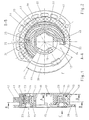
- the device consists of four plastic injection-molded parts, namely a base body 10, an adjusting disk 20, a flexible toothed ring 30 and a release disk 40.
- the four plastic injection-molded parts are placed axially one inside the other during assembly and connected and held together by clipping, so that simple, rational and tool-free assembly results.
- the base body 10 is non-rotatably with a hexagon socket 11 on a hexagon of a shaft, for. B. an actuator or the like, placed and held axially immovably frictionally on the hexagon of the shaft by means of resilient lugs 12.
- a radial flange 13 is formed on the base body 10, which has two diametrically arranged cutouts 14.
- the adjusting disk 20 is an annular disk with a knurling 21 on its outer circumference.
- a deformation body 22 is integrally formed axially on the inner edge of the adjusting disk 20.
- the deformable body 22 is rotatably supported with its circular cylindrical inner surface on the outer circumference of the base body.
- the deformation body On two diametrical areas of its outer circumference, the deformation body has spring tongues 23, which are separated from the deformation body 22 by incisions 24 running approximately parallel to the tangent plane, so that the free ends of the spring tongues 23 are arranged radially resiliently on the deformation body 22.
- the free ends of the spring tongues 23 projecting somewhat radially beyond the outer circumference of the deformation body 22 are provided with locking projections 25 on their outer surface.
- the flexible toothed ring 30 is placed on the outer circumference of the deformation body 22.
- the flexible toothed ring 30 has locking recesses 31 on its inner circumference, which extend in a predetermined angular division over the entire inner circumference of the toothed ring 30.
- the latching projections 25 of the spring tongues 23 of the deformation body 22 engage resiliently and latching in the latching depressions 31 of the toothed ring 30. In this way, the diametrically arranged spring tongues 23 of the deformation body 22 deform the flexible toothed ring 30 in an elliptical manner.
- the flexible toothed ring 30 has an external toothing 32 on its outer circumference.
- the toothed ring 30 engages with two axially projecting tabs 33 in the recesses 14 of the flange 13 of the base body 10.
- the angular width of the tabs 33 corresponds to the angular width of the recesses 14, so that the toothed ring 30 non-rotatably by the tabs 33 engaging in the recesses 14 the base body 10 is fixed.
- the radial width of the cutouts 14 permits the radial movement of the toothed ring 30 during its elliptical deformation by the spring tongues 23 of the deformation body 22.
- the release disk 40 coaxially surrounds the flexible toothed ring 30.
- the release disk 40 has on its circular cylindrical inner circumference an internal toothing 41, the tooth pitch of which corresponds to the tooth pitch of the external toothing 32 of the flexible toothed ring 30.
- the number of teeth Z A of the internal toothing 41 is somewhat larger than that Number of teeth Z F of the external toothing 32 of the ring gear 30.
- the inner toothing 41 of the engagement plate 40 Z A 96 teeth
- the external teeth 32 of the flexible toothed ring 30 Z F having 88 teeth.
- the diameter of the inner toothing 41 of the release disk 40 is so much larger than the outer diameter of the deformation body 22 that the flexible toothed ring 30 is brought into meshing engagement with the inner toothing 41 of the release disk 40 by the spring tongues 23 of the deformation body 22 in two diametrical angular regions with its outer toothing 32 becomes, while in the remaining angular ranges the elliptically deformed toothed ring 30 with its external toothing 32 does not come into radial engagement with the internal toothing 41 of the release disk 40.
- Means are provided on the outer circumference of the trigger disk 40 which trigger the switching or control process.
- a radially projecting cam 42 is formed on the outer periphery of the trigger plate 40, which triggers a switching operation, for. B. operated a limit switch or the like ..
- the adjusting disk 20 projects with its outer circumference provided with the knurling 21 beyond the outer circumference of the release disk 40, so that the adjusting disk 20 can be easily grasped and rotated by means of its knurling 21.
- the flexible toothed ring 30 is first pushed axially onto the deformation body 22 until it comes into contact with the adjusting disk 20. Then the release disk 40 is pushed axially until it comes to rest on the adjusting disk 20. Finally, the base body 10 is pushed axially into the deformation body 22, and molded on at its end (on the left in FIG. 1) outer locking lugs 15 clipped onto the adjusting disk 20. As a result, the flexible toothed ring 30 and the release disk 40 are held axially between the adjusting disk 20 and the flange 13 of the base body 10.
- the adjusting disk 20 with the deformation body 22 and the release disk 40 are freely rotatable against each other and against the base body 10.
- the flexible toothed ring 30 is rotatably mounted on the base body 10 by means of the tabs 33 which engage in the cutouts 14 of the flange 13.
- the device serves to adjustably assign the triggering process caused by the cam 42 to a specific angular position of the shaft.
- the release disk 40 can be adjusted with the cam 42 in relation to the base body 10 which is seated on the shaft in a rotationally fixed manner.
- the adjusting disk 20 is rotated manually.
- the deformation body 22 formed thereon rotates, the elliptical deformation of the non-rotatable flexible toothed ring 30 moving in accordance with the rotation of the deformation body 22.
- the spring tongues 23 which snap into the locking recesses 31 of the toothed ring 30 with their locking projections 22 have the effect that the further rotation of the adjusting disk 20 with the deformation body 22 takes place in noticeable locking steps corresponding to the angular division of the locking recesses 31 of the flexible toothed ring 30.
- the person rotating the adjusting disk 20 thus clearly feels the gradual further rotation of the deformation body 22.
- the latching of the locking projections 25 into the locking recesses 31 prevents undesired automatic rotation of the deformation body 22 as a result of vibrations and shocks to the shaft.
Landscapes
- Engineering & Computer Science (AREA)
- General Engineering & Computer Science (AREA)
- Mechanical Engineering (AREA)
- Retarders (AREA)
- Chairs For Special Purposes, Such As Reclining Chairs (AREA)
- Gears, Cams (AREA)
- Eye Examination Apparatus (AREA)
- Fittings On The Vehicle Exterior For Carrying Loads, And Devices For Holding Or Mounting Articles (AREA)
- Vehicle Body Suspensions (AREA)
Applications Claiming Priority (2)
| Application Number | Priority Date | Filing Date | Title |
|---|---|---|---|
| DE19518053 | 1995-05-17 | ||
| DE19518053A DE19518053C1 (de) | 1995-05-17 | 1995-05-17 | Vorrichtung zur Auslösung eines Vorgangs in Abhängigkeit von der Winkelstellung einer Welle |
Publications (3)
| Publication Number | Publication Date |
|---|---|
| EP0743474A2 true EP0743474A2 (fr) | 1996-11-20 |
| EP0743474A3 EP0743474A3 (fr) | 1997-06-11 |
| EP0743474B1 EP0743474B1 (fr) | 1999-10-13 |
Family
ID=7762118
Family Applications (1)
| Application Number | Title | Priority Date | Filing Date |
|---|---|---|---|
| EP96102639A Expired - Lifetime EP0743474B1 (fr) | 1995-05-17 | 1996-02-22 | Dispositif de déclenchement d'une action en fonction de la position angulaire d'un arbre |
Country Status (3)
| Country | Link |
|---|---|
| EP (1) | EP0743474B1 (fr) |
| AT (1) | ATE185614T1 (fr) |
| DE (1) | DE19518053C1 (fr) |
Families Citing this family (2)
| Publication number | Priority date | Publication date | Assignee | Title |
|---|---|---|---|---|
| DE102008014222B3 (de) * | 2008-03-16 | 2009-08-20 | Harmonic Drive Polymer Gmbh | Anordnung zum Verschleißausgleich bei insbesondere aus Kunststoff bestehenden sog. "Harmonic-Drive"-Getrieben |
| EP4116604A1 (fr) * | 2021-07-06 | 2023-01-11 | maxon international ag | Disque de roue dentée flexible et roue dentée flexible pour un réducteur en grande série, ainsi que réducteur en grande série |
Family Cites Families (4)
| Publication number | Priority date | Publication date | Assignee | Title |
|---|---|---|---|---|
| US2906143A (en) * | 1955-03-21 | 1959-09-29 | United Shoe Machinery Corp | Strain wave gearing |
| US2943465A (en) * | 1957-12-16 | 1960-07-05 | United Shoe Machinery Corp | Adjustable spline |
| DE4022735A1 (de) * | 1989-07-18 | 1991-01-24 | Candy Mfg Co | Spielfreie phaseneinstellvorrichtung |
| DE4038555A1 (de) * | 1990-12-04 | 1992-06-11 | Michael Fischer | Untersetzungsgetriebe mit flexiblen huelsenrad und abtriebs-kuppelstegen |
-
1995
- 1995-05-17 DE DE19518053A patent/DE19518053C1/de not_active Expired - Lifetime
-
1996
- 1996-02-22 EP EP96102639A patent/EP0743474B1/fr not_active Expired - Lifetime
- 1996-02-22 AT AT96102639T patent/ATE185614T1/de not_active IP Right Cessation
Also Published As
| Publication number | Publication date |
|---|---|
| DE19518053C1 (de) | 1996-08-29 |
| EP0743474A3 (fr) | 1997-06-11 |
| EP0743474B1 (fr) | 1999-10-13 |
| ATE185614T1 (de) | 1999-10-15 |
Similar Documents
| Publication | Publication Date | Title |
|---|---|---|
| DE102015212823B3 (de) | Untersetzungsgetriebe, insbesondere für eine einstellvorrichtung eines kraftfahrzeugsitzes, sowie getriebemotor | |
| DE948261C (de) | Zeitschaltuhr | |
| WO2006037585A1 (fr) | Actionneur rotatif | |
| DE3804352A1 (de) | Verstellvorrichtung fuer sitze | |
| DE102006007600B4 (de) | Drehsteller für elektrische oder elektronische Gräte in einem Kraftfahrzeug | |
| DE69308778T2 (de) | Scheibenwischer mit Drehdämpfer, insbesondere für Kraftfahrzeuge | |
| DE19518053C1 (de) | Vorrichtung zur Auslösung eines Vorgangs in Abhängigkeit von der Winkelstellung einer Welle | |
| DE2631589A1 (de) | Vorrichtung mit skala zum zaehlen von umdrehungen | |
| DE3828508C1 (fr) | ||
| DE102010048601B4 (de) | Eingabevorrichtung mit variablem Betätigungsgefühl | |
| DE2714021C2 (de) | Vorrichtung zum Abschalten der Drehbewegung einer angetriebenen Welle | |
| EP3882940A1 (fr) | Appareil d'installation électrique/électronique | |
| DE3337574C2 (fr) | ||
| DE4415134C2 (de) | Drehstellungs-Anzeigevorrichtung | |
| CH607265A5 (fr) | ||
| DE2618711B2 (de) | Federbelastete Rutschkupplung fur einen motorgetriebenen Schraubendreher | |
| DE19548609C2 (de) | Zahnradgetriebe | |
| EP0707541B1 (fr) | Systeme d'entrainement pour une partie reglable d'un vehicule | |
| DE3302772C2 (de) | Steuervorrichtung für Programmschaltgeräte | |
| DE68928714T2 (de) | Dreh-Antriebseinrichtung eines variablen Widerstandes | |
| EP0805468A2 (fr) | Ensemble interrupteur avec au moins deux interrupteurs rotatifs | |
| DE1665310A1 (de) | Potentiometer | |
| DE1289151B (de) | Drehbare Fernsehkanalwaehleinrichtung | |
| DE3139073A1 (de) | Antriebsvorrichtung fuer jalousien oder dergleichen | |
| DE2451407A1 (de) | Schaltvorrichtung |
Legal Events
| Date | Code | Title | Description |
|---|---|---|---|
| PUAI | Public reference made under article 153(3) epc to a published international application that has entered the european phase |
Free format text: ORIGINAL CODE: 0009012 |
|
| AK | Designated contracting states |
Kind code of ref document: A2 Designated state(s): AT CH FR GB IT LI NL |
|
| PUAL | Search report despatched |
Free format text: ORIGINAL CODE: 0009013 |
|
| AK | Designated contracting states |
Kind code of ref document: A3 Designated state(s): AT CH DE FR GB IT LI NL |
|
| 17P | Request for examination filed |
Effective date: 19970626 |
|
| 17Q | First examination report despatched |
Effective date: 19981022 |
|
| GRAG | Despatch of communication of intention to grant |
Free format text: ORIGINAL CODE: EPIDOS AGRA |
|
| GRAG | Despatch of communication of intention to grant |
Free format text: ORIGINAL CODE: EPIDOS AGRA |
|
| GRAH | Despatch of communication of intention to grant a patent |
Free format text: ORIGINAL CODE: EPIDOS IGRA |
|
| RBV | Designated contracting states (corrected) |
Designated state(s): AT CH FR GB IT LI NL |
|
| REG | Reference to a national code |
Ref country code: DE Ref legal event code: 8566 |
|
| GRAH | Despatch of communication of intention to grant a patent |
Free format text: ORIGINAL CODE: EPIDOS IGRA |
|
| GRAA | (expected) grant |
Free format text: ORIGINAL CODE: 0009210 |
|
| AK | Designated contracting states |
Kind code of ref document: B1 Designated state(s): AT CH FR GB IT LI NL |
|
| PG25 | Lapsed in a contracting state [announced via postgrant information from national office to epo] |
Ref country code: NL Free format text: LAPSE BECAUSE OF FAILURE TO SUBMIT A TRANSLATION OF THE DESCRIPTION OR TO PAY THE FEE WITHIN THE PRESCRIBED TIME-LIMIT Effective date: 19991013 |
|
| REF | Corresponds to: |
Ref document number: 185614 Country of ref document: AT Date of ref document: 19991015 Kind code of ref document: T |
|
| REG | Reference to a national code |
Ref country code: CH Ref legal event code: EP |
|
| ITF | It: translation for a ep patent filed | ||
| ET | Fr: translation filed | ||
| PGFP | Annual fee paid to national office [announced via postgrant information from national office to epo] |
Ref country code: FR Payment date: 20000215 Year of fee payment: 5 |
|
| PGFP | Annual fee paid to national office [announced via postgrant information from national office to epo] |
Ref country code: GB Payment date: 20000216 Year of fee payment: 5 |
|
| PG25 | Lapsed in a contracting state [announced via postgrant information from national office to epo] |
Ref country code: AT Free format text: LAPSE BECAUSE OF NON-PAYMENT OF DUE FEES Effective date: 20000222 |
|
| PG25 | Lapsed in a contracting state [announced via postgrant information from national office to epo] |
Ref country code: LI Free format text: LAPSE BECAUSE OF NON-PAYMENT OF DUE FEES Effective date: 20000229 Ref country code: CH Free format text: LAPSE BECAUSE OF NON-PAYMENT OF DUE FEES Effective date: 20000229 |
|
| NLV1 | Nl: lapsed or annulled due to failure to fulfill the requirements of art. 29p and 29m of the patents act | ||
| PLBE | No opposition filed within time limit |
Free format text: ORIGINAL CODE: 0009261 |
|
| STAA | Information on the status of an ep patent application or granted ep patent |
Free format text: STATUS: NO OPPOSITION FILED WITHIN TIME LIMIT |
|
| 26N | No opposition filed | ||
| REG | Reference to a national code |
Ref country code: CH Ref legal event code: PL |
|
| PG25 | Lapsed in a contracting state [announced via postgrant information from national office to epo] |
Ref country code: GB Free format text: LAPSE BECAUSE OF NON-PAYMENT OF DUE FEES Effective date: 20010222 |
|
| GBPC | Gb: european patent ceased through non-payment of renewal fee |
Effective date: 20010222 |
|
| PG25 | Lapsed in a contracting state [announced via postgrant information from national office to epo] |
Ref country code: FR Free format text: LAPSE BECAUSE OF NON-PAYMENT OF DUE FEES Effective date: 20011031 |
|
| REG | Reference to a national code |
Ref country code: FR Ref legal event code: ST |
|
| PG25 | Lapsed in a contracting state [announced via postgrant information from national office to epo] |
Ref country code: IT Free format text: LAPSE BECAUSE OF NON-PAYMENT OF DUE FEES;WARNING: LAPSES OF ITALIAN PATENTS WITH EFFECTIVE DATE BEFORE 2007 MAY HAVE OCCURRED AT ANY TIME BEFORE 2007. THE CORRECT EFFECTIVE DATE MAY BE DIFFERENT FROM THE ONE RECORDED. Effective date: 20050222 |