EP0743527A2 - Geräteprüfvorrichtung mit Kabelschwenkführung und Installationsverfahren - Google Patents
Geräteprüfvorrichtung mit Kabelschwenkführung und Installationsverfahren Download PDFInfo
- Publication number
- EP0743527A2 EP0743527A2 EP96302739A EP96302739A EP0743527A2 EP 0743527 A2 EP0743527 A2 EP 0743527A2 EP 96302739 A EP96302739 A EP 96302739A EP 96302739 A EP96302739 A EP 96302739A EP 0743527 A2 EP0743527 A2 EP 0743527A2
- Authority
- EP
- European Patent Office
- Prior art keywords
- test head
- adapter ring
- head adapter
- cam followers
- testing system
- Prior art date
- Legal status (The legal status is an assumption and is not a legal conclusion. Google has not performed a legal analysis and makes no representation as to the accuracy of the status listed.)
- Granted
Links
Images


Classifications
-
- G—PHYSICS
- G01—MEASURING; TESTING
- G01R—MEASURING ELECTRIC VARIABLES; MEASURING MAGNETIC VARIABLES
- G01R1/00—Details of instruments or arrangements of the types included in groups G01R5/00 - G01R13/00 and G01R31/00
- G01R1/02—General constructional details
- G01R1/06—Measuring leads; Measuring probes
- G01R1/067—Measuring probes
- G01R1/06705—Apparatus for holding or moving single probes
-
- G—PHYSICS
- G01—MEASURING; TESTING
- G01R—MEASURING ELECTRIC VARIABLES; MEASURING MAGNETIC VARIABLES
- G01R1/00—Details of instruments or arrangements of the types included in groups G01R5/00 - G01R13/00 and G01R31/00
- G01R1/02—General constructional details
- G01R1/04—Housings; Supporting members; Arrangements of terminals
Definitions
- a positioner able to move along a support structure, carries the test head to the desired location at which the test head is positioned to connect to and dock with the device handler.
- the test head is attached to the positioner so that the test head can achieve six degrees of freedom.
- the cable In the tumble type, the cable is slung beneath the test head so that it connects to the side of the test head opposite the mechanism by which the test head is attached, at its center of gravity, to the positioner.
- This arrangement avoids the complexity and expense of a cable-pivot type approach.
- this arrangement allows the cable to hang beneath the test head to beyond the side of the test head.
- the cable often gets in the way of the operator of the test system and very large test heads are limited in how low they may be positioned before the cables will touch the floor when the test head is in its down position when the interface plane is perpendicular to the floor.
- the tumble-type arrangement requires a lengthy cable because it extends completely across the bottom of the test head for certain orientations of the test head.
- test head is also held at its center of gravity by the positioner.
- the cable and positioner are attached to the test head on opposite ends of the test head.
- One disadvantage of this type of arrangement is that it cannot access, from underneath, horizontal plane handlers which are built like two pedestal office desks; the positioner stands where one pedestal of such a desk would be located.
- a second cable pivot-type arrangement involves passing the cable through the mechanism by which the test head is attached to the positioner.
- This mechanism is arranged to permit pivotal movement of the test head.
- Such mechanisms include an inner ring which, through bearings, is spaced from and able to rotate in an outer ring.
- One disadvantage of these mechanisms is that the mechanism is expensive: the bearings themselves and the precise machining necessary to load the bearings in the ring are costly.
- Continual bending, twisting, and insertion/removal of such cables is inherent when the system is used to test a variety of probers and handlers. Accordingly, the fatigue life of the cables is an important concern. Because fatigue life of materials from which cables are made decreases with increasing stress and the applied stress is proportional to the length of cable over which a bend or twist occurs, it is advantageous to control the length of the cable encompassing the bend or twist.
- Another object is safety and ease of operation of the test head positioning system.
- Related objects are to provide a system which properly balances the test head in the cable pivot arrangement for acceptable handling.
- Still another object is to provide a system able to dock to a variety of probers and handlers, including those built like pedestal desks, and to position especially large test heads low to the floor without having the cables touch the floor. It is also advantageous to allow mounting of the test head directly to the cable pivot arrangement.
- an object of the present invention is to provide a system which can be manufactured cost efficiently, especially by eliminating alignment tolerance requirements.
- the present invention provides a device testing system with a support structure and a positioner able to move along that support structure. Also included is a cable pivot housing defining a substantially circular passage and having a connecting structure on only one side, so that the passage is partly closed on that side and completely open on the opposite side.
- a single piece test head adapter ring is rotatably positioned in the passage of the housing. The ring is installed in the housing by a method of installation which includes attaching cam followers to the housing through an opening included in the ring.
- the testing system further includes a test head, attached to the test head adapter ring so that pivotal movement of the test head is permitted; a test cabinet; a cable connected between the test cabinet and the test head and passing through the test head adapter ring; and a cable support.
- Figure 1A is a perspective view of an electronic device testing system constructed in accordance with the present invention.
- the system is generally similar to the one described and illustrated in U.S. Patents No. 4,893,074 and 4,589,815.
- the system includes a support structure (not shown) which maintains a main shaft 10 in the vertical direction (the y-direction of Figure 1) and a positioner 12 .
- Positioner 12 can move vertically along shaft 10 in the y-direction and can rotate about shaft 10 in the ⁇ y direction.
- Positioner 12 can be fixed relative to shaft 10 by tightening main lock collar 14 using main lock 16.
- Positioner 12 includes a main arm 18 , a forearm assembly 20 , and a wrist assembly 22 .
- Forearm assembly 20 is attached to main arm 18 at forearm mount blocks 34 so that forearm assembly 20 can move vertically along shaft 10 in the y-direction.
- Forearm assembly 20 has a vertical elbow shaft 28 displaced in the z-direction from the vertical axis along which main shaft 10 is disposed. Forearm assembly 20 can rotate in the ⁇ y direction about shaft 28 relative to main arm 18 . Lock collar 30 , activated by elbow lock 32 , fixes forearm assembly 20 on shaft 28 .
- Wrist assembly 22 is attached to forearm assembly 20 .
- Wrist assembly 22 includes a wrist housing 36 having a circular portion, through which a vertical wrist shaft 38 is disposed, and a block face. The circular portion and block face of wrist housing 36 may be formed as a single casting.
- Vertical wrist shaft 38 is further displaced in the z-direction from elbow shaft 28 and main shaft 10 . Note that the combination of possible rotations about the three, separate, vertical shafts 10, 28, and 38 allows the test head 56 (see Figure 2A) to be positioned along the x and z axes.
- Wrist assembly 22 can rotate in the ⁇ y direction about vertical wrist shaft 38 --unless locked in place by vertical wrist lock 40 .
- Wrist assembly 22 can also rotate about the z axis. As shown in Figure 1B, wrist assembly 22 also has a horizontal circular portion through which a horizontal wrist shaft 44A is disposed. Horizontal wrist shaft 44A has a flange portion 44B which is attached to the circular flange end 48 of cable pivot adapter 46 . To prevent such rotation, horizontal wrist lock 42 can be used to fix horizontal wrist shaft 44A of wrist assembly 22 in position. Cable pivot adapter 46 is affixed to horizontal wrist shaft 44A by conventional screws, bolts, pins, or the like.
- test head adapter ring 54 For acceptable handling, it is very important that the cantilever load created by, among other components, the cable and test head 56 (shown in Figure 2B and described in greater detail below), be balanced in test head adapter ring 54 for ⁇ Z movement. Without proper balancing, a human operator rotating a 500 kg test head in the ⁇ Z direction would be handling approximately 1600 Newton-meters of torque. For a human operator to be handling this amount of torque is unsafe.
- Fig. 1C shows one way in which balancing is achieved.
- a spring assembly 106 is attached through spring housing 108 to wrist housing 36 . Inside housing 108 , two, separate springs are provided to compensate for the cantilever load.
- spring housing 108 On the load side of cable pivot housing 52 (in the positive x-direction), spring housing 108 contains a disc spring 181 .
- Disc spring 181 is guided by disc spring piston 183 and installed by a disc spring screw 110 .
- a gimbal pin 112A connects the disc spring and piston assembly of spring assembly 106 to wrist assembly 22 via horizontal wrist shaft 44A .
- spring housing 108 contains coil spring 185 .
- Coil spring 185 is guided by coil spring piston 187 and adjusted by a coil spring screw 114.
- Gimbal pin 112B connects coil spring 185 and coil spring piston 187 of spring assembly 106 to wrist assembly 22 via horizontal wrist shaft 44A .
- the coil spring is used for calibration, to compensate for tolerance inherent in disc spring 181 .
- Cable pivot adapter 46 includes flange 48 and a beam 50 .
- Beam 50 is attached (welded or formed as an integral casting, for example) to flange 48 on one end.
- Cable pivot adapter 46 is affixed to horizontal wrist shaft 44A by conventional screws, bolts, pins, or the like which extend through openings in flange 48 to be received in respective corresponding openings in flange portion 44B .
- Beam 50 is attached (through screws, bolts, or the like) to a cable pivot housing 52 on its opposite end, thereby connecting flange 48 and cable pivot housing 52.
- Cable pivot housing 52 retains test head adapter ring 54 , allowing ring 54 to rotate (in the ⁇ x direction) within housing 52 in a manner described below.
- Test head 56 is attached to ring 54 in a number of possible ways, some of which are described below, allowing ring 54 to transfer movement to test head 56 .
- Test head 56 interacts with the electronic interface components (connectors, pogo pins, printed circuit boards, and the like) of the system to be tested (not shown).
- electronic interface components connectors, pogo pins, printed circuit boards, and the like
- motion of the test head during such action must be precisely in line with the motion axis of the electronic interface components. Accordingly, test head 56 must be able to move accurately and effortlessly in any or all of the six degrees of motion freedom of a Cartesian coordinate system during the docking and undocking action.
- the invention achieves six degrees of freedom of motion by carefully assuring that balance is maintained (as described below) on each axis of motion in the design of both the positioner 12 and the test head adapter ring 54 elements of the device testing system.
- a cable usually composed of a number of individual cables (not shown), extends into test head 56 through test head adapter ring 54 .
- Electronic signals generated by test head 56 and power are delivered along these cables to and from a test cabinet (not shown).
- a telescopic cable support 58 is provided to carry the cables.
- Support 58 has spherical bearings on each end which allow freedom of movement. Support 58 is more fully described in U.S. Patent No. 4,893,070.
- cable pivot housing 52 only partially surrounds test head adapter ring 54 .
- Housing 52 has a lip 60 having two holes 62 into which two horizontal cam followers 64 are inserted (in the x-direction). Perpendicular to horizontal cam followers 64 , three radial cam followers 66 are inserted into the inside radial surface 68 of cable pivot housing 52 into three holes 63 .
- the wall 70 of housing 52 which faces test head 56 is open; wall 70 does not contain a lip or flange similar to lip 60 on the opposite side of housing 52 .
- Test head adapter ring 54 is formed as a single piece ring, generally as aluminum plate or tubing. Ring 54 includes guide 82 and groove 84 . Steel may also be used. However, steel is typically heavier than aluminum and more expensive.
- Guide 82 is formed around the outside of test head adapter ring 54 in the side opposite wall 70 .
- Horizontal cam followers 64 engage guide 82 when ring 54 is in position inside cable pivot housing 52 .
- a radial groove 84 is formed around the circumference of ring 54 . Groove 84 engages radial cam followers 66 when ring 54 is in position inside housing 52 .
- Horizontal cam followers 64 and radial cam followers 66 are standard hardware, forming complete units containing needle bearings. Such cam followers are inexpensive relative to the big-diameter ball bearings previously used in conventional cable pivot arrangements, although they are as useful in high-load carrying parts such as test head adapter ring 54 .
- two horizontal cam followers 64 and three radial cam followers 66 are preferable.
- the horizontal cam followers 64 are disposed perpendicular to the radial cam followers 66 .
- the two horizontal cam followers 64 and two of the three radial cam followers 66 are linearly disposed along imaginary, intersecting lines, with the third radial cam follower 66 disposed midway between the two horizontal-radial cam follower pairs.
- cam followers are advantageous because it minimizes alignment tolerance requirements.
- the cam followers In order to share the cantilever load imposed on test head adapter ring 54 , the cam followers must be in line. If three horizontal cam followers 64 were used, for example, they would not only have to be critically perpendicular to the radial cam followers 66 , but they would have to be in line so that they properly shared the load. Because only two horizontal cam followers 64 are used, their perpendicularity is not as critical and alignment tolerances are more easily met.
- Test head 56 may be mounted to test head adapter ring 54 in a variety of ways. Three embodiments of the attachment between the test head 56 and the ring 54 are illustrated in the drawing.
- a test head mount 86 can be affixed to the inside surface 88 of test head adapter ring 54 or to both the inside surface 88 and the face 104 of ring 54 (or to face 104 as shown in Figure 4 and as described below). Radial screws, pins, or the like 90 engaging passages 92 in test head mount 86 may be used to position test head mount 86 .
- a rod 94 affixed to test head 56 on one end, is attached to (and may be integral with) test head mount 86 . Rod 94 may extend beyond test head mount 86 and attaches to cable support 58 on its opposite end.
- Figure 4 shows an alternative attachment between the test head 56 and the test head adapter ring 54 .
- a cradle, harness, or yoke 96 supporting test head 56 is attached directly to the face 104 of ring 54 without using additional structure such as test head mount 86 and rod 94 .
- Conventional screws, bolts, pins, or the like 98 may be used to attach the elements.
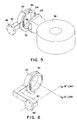
- Figure 5 illustrates a third embodiment of the attachment between the test head 56 and the test head adapter ring 54 .
- a projection 102 is formed on test head 56 .
- Projection 102 can be attached, by conventional means, directly to ring 54 .
- test head adapter ring 54 Given the constraints on the outside diameter of test head adapter ring 54, the inside diameter of ring 54 is reduced as the thickness of face 104 is increased; but that inside diameter must be sufficient to pass the relatively large cable to test head 56 .
- the present invention can incorporate a thinner face 104 yet achieve the consequent mounting advantage.
- the center of gravity of the load of test head 56 should pass through the center of ring 54 so that the test head remains balanced as it is rotated about the ⁇ x axis.
- the center of gravity (C g ) of the test head load may not be symmetrically aligned if, for example, the cable does not connect to test head 56 symmetrically about the C g (i.e. the cable may be attached to an edge of test head 56 in certain designs). Such misalignment can exacerbate the balancing difficulty.
- the embodiment of the present invention shown in Figure 1A use spring assembly 106 to balance the load of the test head (and its associated cables). That load may also be balanced, without using a spring assembly, by providing test head adapter ring 54 in an offset position, as shown in Figure 6. To assure that the center of gravity of the load passes through the center of ring 54 in the x-direction and through the center of flange 48 in the z-direction, beam 50 is formed in a z-shaped configuration.
- a conventional cable pivot lock knob 189 is typically placed in cable pivot housing 52 and can engage test head adapter ring 54 to lock ring 54 in position.
- a device testing system which comprises a support structure, a positioner, a cable pivot housing defining a substantially circular passage completely open on one side, a single piece test head adapter ring, a test head, a test cabinet, a cable, and a cable support
- a device testing system which comprises a support structure, a positioner, a cable pivot housing defining a substantially circular passage completely open on one side, a single piece test head adapter ring, a test head, a test cabinet, a cable, and a cable support
Landscapes
- Physics & Mathematics (AREA)
- General Physics & Mathematics (AREA)
- Tests Of Electronic Circuits (AREA)
- Testing Of Short-Circuits, Discontinuities, Leakage, Or Incorrect Line Connections (AREA)
- A Measuring Device Byusing Mechanical Method (AREA)
- Testing Or Measuring Of Semiconductors Or The Like (AREA)
- Cable Accessories (AREA)
- Insertion, Bundling And Securing Of Wires For Electric Apparatuses (AREA)
Applications Claiming Priority (2)
| Application Number | Priority Date | Filing Date | Title |
|---|---|---|---|
| US08/425,921 US5608334A (en) | 1995-04-20 | 1995-04-20 | Device testing system with cable pivot and method of installation |
| US425921 | 1995-04-20 |
Publications (3)
| Publication Number | Publication Date |
|---|---|
| EP0743527A2 true EP0743527A2 (de) | 1996-11-20 |
| EP0743527A3 EP0743527A3 (de) | 1997-07-23 |
| EP0743527B1 EP0743527B1 (de) | 2005-03-30 |
Family
ID=23688581
Family Applications (1)
| Application Number | Title | Priority Date | Filing Date |
|---|---|---|---|
| EP96302739A Expired - Lifetime EP0743527B1 (de) | 1995-04-20 | 1996-04-19 | Geräteprüfvorrichtung mit Kabelschwenkführung und Installationsverfahren |
Country Status (9)
| Country | Link |
|---|---|
| US (1) | US5608334A (de) |
| EP (1) | EP0743527B1 (de) |
| JP (1) | JPH08292238A (de) |
| KR (1) | KR100247329B1 (de) |
| CN (1) | CN1084477C (de) |
| AT (1) | ATE292285T1 (de) |
| DE (1) | DE69634524T2 (de) |
| MY (1) | MY112044A (de) |
| SG (1) | SG42391A1 (de) |
Cited By (1)
| Publication number | Priority date | Publication date | Assignee | Title |
|---|---|---|---|---|
| EP0979389A4 (de) * | 1997-04-30 | 2000-07-19 | Credence Systems Corp | Kabelanondnung für prüfvorrichtung |
Families Citing this family (20)
| Publication number | Priority date | Publication date | Assignee | Title |
|---|---|---|---|---|
| JP3869465B2 (ja) * | 1995-02-23 | 2007-01-17 | テラダイン・インコーポレーテッド | 自動テスト装置のテストヘッド用マニピュレータ |
| US6271658B1 (en) | 1998-10-19 | 2001-08-07 | St Assembly Test Services Pte, Ltd. | Universal Docking System |
| US6253458B1 (en) * | 1998-12-08 | 2001-07-03 | Faro Technologies, Inc. | Adjustable counterbalance mechanism for a coordinate measurement machine |
| MY144519A (en) * | 2000-03-01 | 2011-09-30 | Intest Corp | Vertical counter balanced test head manipulator |
| US6408500B1 (en) * | 2000-09-15 | 2002-06-25 | James Orsillo | Method of retrofitting a probe station |
| WO2002024400A2 (en) * | 2000-09-20 | 2002-03-28 | Intest Ip Corp. | Electronic test head positioner |
| CN1280635C (zh) * | 2001-07-16 | 2006-10-18 | 因泰斯特Ip公司 | 测试头对接系统及方法 |
| US7464630B2 (en) * | 2001-08-27 | 2008-12-16 | Flow International Corporation | Apparatus for generating and manipulating a high-pressure fluid jet |
| US6897645B2 (en) * | 2001-12-29 | 2005-05-24 | Vincent Hing Chung So | Docking system and method for docking in automated testing systems |
| US6646431B1 (en) | 2002-01-22 | 2003-11-11 | Elite E/M, Inc. | Test head manipulator |
| US6771062B1 (en) * | 2003-05-14 | 2004-08-03 | Advantest Corporation | Apparatus for supporting and manipulating a testhead in an automatic test equipment system |
| JP2007533956A (ja) * | 2003-08-06 | 2007-11-22 | インテスト コーポレイション | テストヘッド位置決めシステム |
| TWI490513B (zh) | 2006-12-29 | 2015-07-01 | Intest Corp | 用於使負載沿平移軸線平移之負載定位系統以及使負載達到平衡之方法 |
| WO2008085463A1 (en) * | 2006-12-29 | 2008-07-17 | In Test Corporation | Test head positioning system and method |
| US8212578B1 (en) | 2008-03-17 | 2012-07-03 | Intest Corporation | Test head positioner system |
| US8981807B2 (en) | 2010-07-27 | 2015-03-17 | Intest Corporation | Positioner system and method of positioning |
| EP2732298A1 (de) | 2011-07-12 | 2014-05-21 | Intest Corporation | Verfahren und vorrichtung zum andocken eines testkopfes an einem peripheriegerät |
| KR102353935B1 (ko) * | 2013-09-30 | 2022-01-19 | 인테스트 코포레이션 | 테스트 헤드를 주변부에 도킹하기 위한 장치 및 방법 |
| DE102014112105A1 (de) * | 2014-08-25 | 2016-02-25 | Phoenix Contact Gmbh & Co. Kg | Halterungseinrichtung für eine Rogowskispule |
| CN113176102B (zh) * | 2021-04-12 | 2022-09-06 | 中国煤炭科工集团太原研究院有限公司 | 一种模拟矿用卷电缆装置横向摆动工况试验台及试验方法 |
Family Cites Families (14)
| Publication number | Priority date | Publication date | Assignee | Title |
|---|---|---|---|---|
| US3128887A (en) * | 1960-02-25 | 1964-04-14 | Mechanical manipulators for the displacement of | |
| GB1508348A (en) * | 1975-06-10 | 1978-04-26 | Mark Products | Seismometer |
| US4160207A (en) * | 1977-06-27 | 1979-07-03 | Haines Fred E | Printed circuit board tester with removable head |
| US4517512A (en) * | 1982-05-24 | 1985-05-14 | Micro Component Technology, Inc. | Integrated circuit test apparatus test head |
| US4588346A (en) * | 1982-08-25 | 1986-05-13 | Intest Corporation | Positioner for maintaining an object in a substantially weightless condition |
| US4705447A (en) * | 1983-08-11 | 1987-11-10 | Intest Corporation | Electronic test head positioner for test systems |
| US4527942A (en) * | 1982-08-25 | 1985-07-09 | Intest Corporation | Electronic test head positioner for test systems |
| US4650391A (en) * | 1985-02-25 | 1987-03-17 | Amp Incorporated | Electrical connector pick-up station |
| US4665360A (en) * | 1985-03-11 | 1987-05-12 | Eaton Corporation | Docking apparatus |
| DE3615941A1 (de) * | 1986-05-12 | 1987-11-19 | Willberg Hans Heinrich | Geraet zum pruefen von elektronischen bauelementen, insbesondere ic's |
| EP0308348B1 (de) * | 1987-09-17 | 1993-02-10 | Schlumberger Industries | Prüfkopfmanipulator für das automatische Prüfen |
| US4893074A (en) * | 1988-05-13 | 1990-01-09 | Intest Corporation | Electronic device testing system |
| US5030869A (en) * | 1990-07-25 | 1991-07-09 | Intest Corporation | Device testing system with cable pivot |
| US5241870A (en) * | 1991-07-22 | 1993-09-07 | Intest Corporation | Test head manipulator |
-
1995
- 1995-04-20 US US08/425,921 patent/US5608334A/en not_active Expired - Fee Related
-
1996
- 1996-04-19 SG SG1996009307A patent/SG42391A1/en unknown
- 1996-04-19 MY MYPI96001496A patent/MY112044A/en unknown
- 1996-04-19 KR KR1019960011927A patent/KR100247329B1/ko not_active Expired - Fee Related
- 1996-04-19 AT AT96302739T patent/ATE292285T1/de not_active IP Right Cessation
- 1996-04-19 JP JP8098089A patent/JPH08292238A/ja not_active Abandoned
- 1996-04-19 EP EP96302739A patent/EP0743527B1/de not_active Expired - Lifetime
- 1996-04-19 DE DE69634524T patent/DE69634524T2/de not_active Expired - Fee Related
- 1996-04-22 CN CN96104910.3A patent/CN1084477C/zh not_active Expired - Fee Related
Cited By (1)
| Publication number | Priority date | Publication date | Assignee | Title |
|---|---|---|---|---|
| EP0979389A4 (de) * | 1997-04-30 | 2000-07-19 | Credence Systems Corp | Kabelanondnung für prüfvorrichtung |
Also Published As
| Publication number | Publication date |
|---|---|
| MY112044A (en) | 2001-03-31 |
| JPH08292238A (ja) | 1996-11-05 |
| ATE292285T1 (de) | 2005-04-15 |
| US5608334A (en) | 1997-03-04 |
| DE69634524T2 (de) | 2005-09-01 |
| CN1138165A (zh) | 1996-12-18 |
| CN1084477C (zh) | 2002-05-08 |
| EP0743527A3 (de) | 1997-07-23 |
| EP0743527B1 (de) | 2005-03-30 |
| KR100247329B1 (ko) | 2000-03-15 |
| DE69634524D1 (de) | 2005-05-04 |
| SG42391A1 (en) | 1997-08-15 |
Similar Documents
| Publication | Publication Date | Title |
|---|---|---|
| US5608334A (en) | Device testing system with cable pivot and method of installation | |
| EP0468906B1 (de) | Geräteprüfvorrichtung mit Kabelschwenkführung | |
| US5241870A (en) | Test head manipulator | |
| US20060001416A1 (en) | Test head positioner system | |
| US4588346A (en) | Positioner for maintaining an object in a substantially weightless condition | |
| EP0342045B1 (de) | Testsystem für einen elektronischen Apparat | |
| US8035406B2 (en) | Test head positioning system and method | |
| US4705447A (en) | Electronic test head positioner for test systems | |
| US6888343B1 (en) | Test head manipulator | |
| CN114777689B (zh) | 摆动式回转轴定位精度检测工装 | |
| EP0237698A2 (de) | Einstellvorrichtung für elektronische Testköpfe | |
| US7135854B2 (en) | Rear-mounted gimbal for supporting test head | |
| US7221175B2 (en) | Self-aligning docking system for electronic device testing | |
| EP1322964B1 (de) | Positionierer für elektronische testköpfe | |
| HK1019931A (en) | Test head manipulator |
Legal Events
| Date | Code | Title | Description |
|---|---|---|---|
| PUAI | Public reference made under article 153(3) epc to a published international application that has entered the european phase |
Free format text: ORIGINAL CODE: 0009012 |
|
| AK | Designated contracting states |
Kind code of ref document: A2 Designated state(s): AT BE CH DE FR GB IT LI SE |
|
| PUAL | Search report despatched |
Free format text: ORIGINAL CODE: 0009013 |
|
| AK | Designated contracting states |
Kind code of ref document: A3 Designated state(s): AT BE CH DE FR GB IT LI SE |
|
| 17P | Request for examination filed |
Effective date: 19971201 |
|
| RAP1 | Party data changed (applicant data changed or rights of an application transferred) |
Owner name: INTEST IP CORP. |
|
| 17Q | First examination report despatched |
Effective date: 20030328 |
|
| RIC1 | Information provided on ipc code assigned before grant |
Ipc: 7G 01R 1/073 B Ipc: 7G 01R 1/067 A |
|
| GRAP | Despatch of communication of intention to grant a patent |
Free format text: ORIGINAL CODE: EPIDOSNIGR1 |
|
| GRAS | Grant fee paid |
Free format text: ORIGINAL CODE: EPIDOSNIGR3 |
|
| GRAA | (expected) grant |
Free format text: ORIGINAL CODE: 0009210 |
|
| AK | Designated contracting states |
Kind code of ref document: B1 Designated state(s): AT BE CH DE FR GB IT LI SE |
|
| PG25 | Lapsed in a contracting state [announced via postgrant information from national office to epo] |
Ref country code: LI Free format text: LAPSE BECAUSE OF FAILURE TO SUBMIT A TRANSLATION OF THE DESCRIPTION OR TO PAY THE FEE WITHIN THE PRESCRIBED TIME-LIMIT Effective date: 20050330 Ref country code: IT Free format text: LAPSE BECAUSE OF FAILURE TO SUBMIT A TRANSLATION OF THE DESCRIPTION OR TO PAY THE FEE WITHIN THE PRE;WARNING: LAPSES OF ITALIAN PATENTS WITH EFFECTIVE DATE BEFORE 2007 MAY HAVE OCCURRED AT ANY TIME BEFORE 2007. THE CORRECT EFFECTIVE DATE MAY BE DIFFERENT FROM THE ONE RECORDED.SCRIBED TIME-LIMIT Effective date: 20050330 Ref country code: CH Free format text: LAPSE BECAUSE OF FAILURE TO SUBMIT A TRANSLATION OF THE DESCRIPTION OR TO PAY THE FEE WITHIN THE PRESCRIBED TIME-LIMIT Effective date: 20050330 Ref country code: BE Free format text: LAPSE BECAUSE OF FAILURE TO SUBMIT A TRANSLATION OF THE DESCRIPTION OR TO PAY THE FEE WITHIN THE PRESCRIBED TIME-LIMIT Effective date: 20050330 Ref country code: AT Free format text: LAPSE BECAUSE OF FAILURE TO SUBMIT A TRANSLATION OF THE DESCRIPTION OR TO PAY THE FEE WITHIN THE PRESCRIBED TIME-LIMIT Effective date: 20050330 |
|
| REG | Reference to a national code |
Ref country code: GB Ref legal event code: FG4D |
|
| REG | Reference to a national code |
Ref country code: CH Ref legal event code: EP |
|
| REF | Corresponds to: |
Ref document number: 69634524 Country of ref document: DE Date of ref document: 20050504 Kind code of ref document: P |
|
| PG25 | Lapsed in a contracting state [announced via postgrant information from national office to epo] |
Ref country code: GB Free format text: LAPSE BECAUSE OF NON-PAYMENT OF DUE FEES Effective date: 20050630 |
|
| REG | Reference to a national code |
Ref country code: CH Ref legal event code: PL |
|
| PLBE | No opposition filed within time limit |
Free format text: ORIGINAL CODE: 0009261 |
|
| STAA | Information on the status of an ep patent application or granted ep patent |
Free format text: STATUS: NO OPPOSITION FILED WITHIN TIME LIMIT |
|
| GBPC | Gb: european patent ceased through non-payment of renewal fee |
Effective date: 20050630 |
|
| 26N | No opposition filed |
Effective date: 20060102 |
|
| EN | Fr: translation not filed | ||
| PGFP | Annual fee paid to national office [announced via postgrant information from national office to epo] |
Ref country code: DE Payment date: 20070430 Year of fee payment: 12 |
|
| PG25 | Lapsed in a contracting state [announced via postgrant information from national office to epo] |
Ref country code: SE Free format text: LAPSE BECAUSE OF FAILURE TO SUBMIT A TRANSLATION OF THE DESCRIPTION OR TO PAY THE FEE WITHIN THE PRESCRIBED TIME-LIMIT Effective date: 20050630 |
|
| PG25 | Lapsed in a contracting state [announced via postgrant information from national office to epo] |
Ref country code: FR Free format text: LAPSE BECAUSE OF NON-PAYMENT OF DUE FEES Effective date: 20050430 |
|
| PG25 | Lapsed in a contracting state [announced via postgrant information from national office to epo] |
Ref country code: FR Free format text: LAPSE BECAUSE OF NON-PAYMENT OF DUE FEES Effective date: 20050330 |
|
| PG25 | Lapsed in a contracting state [announced via postgrant information from national office to epo] |
Ref country code: DE Free format text: LAPSE BECAUSE OF NON-PAYMENT OF DUE FEES Effective date: 20081101 |