EP0743530A2 - Testvorrichtung für elektronische Bauteile - Google Patents
Testvorrichtung für elektronische Bauteile Download PDFInfo
- Publication number
- EP0743530A2 EP0743530A2 EP96650017A EP96650017A EP0743530A2 EP 0743530 A2 EP0743530 A2 EP 0743530A2 EP 96650017 A EP96650017 A EP 96650017A EP 96650017 A EP96650017 A EP 96650017A EP 0743530 A2 EP0743530 A2 EP 0743530A2
- Authority
- EP
- European Patent Office
- Prior art keywords
- heat transfer
- base plate
- transfer means
- support plate
- temperature controlled
- Prior art date
- Legal status (The legal status is an assumption and is not a legal conclusion. Google has not performed a legal analysis and makes no representation as to the accuracy of the status listed.)
- Withdrawn
Links
Images



Classifications
-
- G—PHYSICS
- G01—MEASURING; TESTING
- G01R—MEASURING ELECTRIC VARIABLES; MEASURING MAGNETIC VARIABLES
- G01R31/00—Arrangements for testing electric properties; Arrangements for locating electric faults; Arrangements for electrical testing characterised by what is being tested not provided for elsewhere
- G01R31/26—Testing of individual semiconductor devices
- G01R31/2601—Apparatus or methods therefor
-
- G—PHYSICS
- G01—MEASURING; TESTING
- G01R—MEASURING ELECTRIC VARIABLES; MEASURING MAGNETIC VARIABLES
- G01R31/00—Arrangements for testing electric properties; Arrangements for locating electric faults; Arrangements for electrical testing characterised by what is being tested not provided for elsewhere
- G01R31/28—Testing of electronic circuits, e.g. by signal tracer
- G01R31/2832—Specific tests of electronic circuits not provided for elsewhere
- G01R31/2836—Fault-finding or characterising
- G01R31/2849—Environmental or reliability testing, e.g. burn-in or validation tests
Definitions
- the invention relates to a test apparatus of the type comprising a temperature controlled chuck which supports the electronic device (such as a semiconductor wafer) under test and directly heats and/or cools the device by conduction.
- the heating and/or cooling is caused by a heat transfer means which is mounted underneath the support plate.
- the temperature ranges for testing in such apparatus are in the region of -135°C to +400°C, or subsets within this range.
- test apparatus are described in various publications including EP 131,375 (Texas Instruments), EP 675,366 (Tokyo Electron Limited), US 4,870,355 (Thermonics Inc.), US 4,491,173 (Temptronic Corporation), and EP 69,592 (Fujitsu).
- various probes are placed precisely on the device under test, and microscopes may also be used. Spacing between test positions on the device under test are often less than 1 micron. Accordingly, excellent accuracy is required and, further, mechanical stability of the chuck over the temperature range is very important. Where there is a wide temperature range during testing, the chuck tends to expand and contract by virtue of thermal expansion and contraction, thus necessitating adjustment of the microscopes and probes. This involves, for example, lifting the probes and then re-setting the device under test. This is a time-consuming exercise which can in some instances lead to inaccuracies and at the very least causes a greater amount of handling of the device under test than is desired.
- a further object is to provide a greater level of electrical isolation of the device under test than has heretofore been the case.
- Another object of the invention is to provide a test apparatus having a chuck which is of simple construction resulting in lower cost production, greater reliability and easier maintenance.
- the invention provides a temperature controlled chuck for a test apparatus for testing electronic devices, characterised in that the chuck comprises :-
- the connector comprises a set of pillars secured to the base and support plates.
- the pillars are arranged symmetrically with respect to the support and base plates.
- the connector has a thermal expansion coefficient less than 3.0 x 10 -6 /°C.
- the mounting means is resilient and supports the heat transfer means in spaced-apart relationship with the base plate.
- the mounting means mounts the heat transfer means on the connector, and the connector comprises a set of pillars rigidly secured to the base and support plates, and in one embodiment, the mounting means comprises spring washers to provide resilience to urge the heat transfer means against the support plate.
- the connector comprises a set of pillars and the mounting means and the connector have a high electrical impedance, in excess of 10 12 Ohms, and in another embodiment, the mounting means comprises a set of electrically insulating washers around the pillars.
- the insulating washers are of ceramic material.
- the heat transfer means engages the support plate via thermal grease.
- the heat transfer means comprises heating and cooling means mounted above a heat sink and connected thereto by thermal grease.
- the heating and cooling means comprises a set of Peltier cells.
- the support plate is of aluminium material.
- the support plate is coated with an inert coating to prevent cross-contamination with a device under test.
- the base plate is of aluminium material.
- the mounting means comprises a deformable part of the base plate supporting the heat transfer means whereby the deformable part distorts locally upon thermal expansion of the heat transfer means without causing distortion of the rigid structure.
- the base plate comprises a heat sink also forming part of the heat transfer means.
- the mounting means comprises a resilient part of the heat transfer means accommodating by compression expansion of other parts of the heat transfer means.
- the invention provides a temperature controlled chuck for a test apparatus for testing electronic devices, the chuck comprising :-
- the invention provides a temperature controlled chuck for a test apparatus for testing electronic devices, the chuck comprising :-
- the invention provides a temperature controlled chuck for a test apparatus for testing electronic devices, the chuck comprising :-
- the invention provides a temperature controlled chuck for a test apparatus for testing electronic devices, the chuck comprising :-
- the invention provides a test apparatus comprising a control unit for controlling the heat transfer means, and an inspection station for supporting the temperature controlled chuck and probes for inspecting devices under test.
- test apparatus 1 indicated generally by the numeral 1.
- the apparatus 1 comprises a test station 2, an electronic controller 3 and a cooling system 4.
- the inspection station 2 comprises a frame 5 having a lower table 6 and an upper table 7.
- the lower table 6 supports a temperature controlled chuck 8 in a manner whereby it causes it to rotate and also to move in a translational manner.
- the upper table 7 supports various microscopes 9 and probes 10 for inspection of a device under test when mounted on the chuck 8.
- the apparatus 1 will typically be used for testing of semiconductor wafers.
- the electronic controller 3 controls heating of a heat transfer means within the chuck 8.
- the cooling system 4 provides coolant to a heat transfer means within the chuck 8.
- the chuck 8 supports the device under test by way of a vacuum, and directly heats or cools the device by temperature conduction through a device support plate of the chuck 8.
- the apparatus may include an enclosure for the device under test and the chuck for the purposes of ensuring that there is no air-borne contamination of the device under test, or condensation at low temperatures.
- An important aspect of the invention is the fact that there is excellent mechanical stability of the chuck 8 across the temperature range of operation so that the device under test remains in much the same absolute position, thus considerably reducing or eliminating the requirement for re-positioning the probes and adjusting the microscopes.
- Another important aspect is the fact that the device under test is electrically isolated, and therefore earth leakage does not occur.
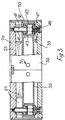
- the chuck 8 comprises a support plate 20 of aluminium material and having a flat upper surface for support of the device under test.
- the support plate 20 has three concentric circular grooves 21, each for independently applying suction to the device under test by virtue of suction lines 22.
- the support plate 20 is gold plated to ensure that there is little or no cross-contamination between the plate 20 and a device under test.
- a heat transfer means in this embodiment comprising a set of four Peltier or thermoelectric cells 25 and a heat sink 30.
- the Peltier cells 25 are capable of both heating and cooling the support plate 20, depending on the polarity of applied voltage.
- the cells 25 are mounted on the heat sink 30 via thermal grease.
- the cells 25 are each connected by leads 26 to the electronic controller 3.
- the heat sink 30 is a hollow chamber having a high internal surface area provided by internal pillars and contains coolant supplied by cooling tubes 31 from the cooling system 4. The purpose of the heat sink 30 is to thermally isolate the lower part of the chuck 8 while the cells 25 are heating, and to provide a relatively low temperature reference when the cells 25 are cooling.
- the chuck 8 also comprises a base plate 35 of aluminium material and having a set of five through-holes 36 in registry with corresponding through-holes 37 in the heat sink 30. These holes are also in registry with sockets in the lower side of the support plate 20.
- the base plate 35 also comprises a set of lower apertures forming a means for connection to the inspection station.
- the chuck 8 also comprises a set of five connectors, namely pillars 40 which rigidly connect the base plate 35 to the support plate 20 to provide a rigid structure.
- Each pillar 40 comprises a shank 41 which engages the base plate 35 and the support plate 20. They also each comprise a spacer 42 in the form of a bolt head mounted above the base plate 35. A spring washer to provide resilience is mounted above the spacer 42, and this in turn supports a ceramic washer 45, upon which the heat sink 30 is mounted. These components form a mounting means for the heat sink 30.
- Each pillar 40 also comprises a lower fastening screw 46 which protrudes upwardly through the base plate 35 to engage within the shank 41. Direct contact of the pillar with the base plate 35 is avoided by use of ceramic washers 47 and 48.
- the shank 41 and the spacer 42 are of InvarTM material.
- This material has a low coefficient of thermal expansion which in this embodiment is 2.2 x 10 -6 /°C. It has an inflection point of 191°C, a Curie temperature of 279°C, and a melting point of 1427°C.
- the chemical composition of this material is as follows :- Chemical Composition (% Weight) C MN SI P S SE 0.06 0.77 0.26 0.012 0.004 0.201 NI+CO CR NI MO CO Fe 36.31 0.14 36.05 L1 + .01 0.26 25.923
- the pillars should have a thermal expansion coefficient of less than 4.0 x 10 -6 /°C and the value is preferably less than 3.0 x 10 -6 /°C.
- the chuck 8 comprises a polyimide protective shroud 50 which surrounds the side edges of the base plate 35, the heat sink 30, the cells 25 and the support plate 20.
- the combination of the support plate 20, the pillars 40 and the base plate 35 provide a rigid mechanical structure mounted on supports of the inspection station. As shown in Fig. 3, there is a space between the heat sink 30 and the base plate 35.
- the heat sink 30 is resiliently mounted on the base plate 35 via the pillars 40. This resilient mounting urges the cells 25 against the underneath surface of the support plate 20 to provide for effective heat conduction.
- a layer of thermal grease is applied between the thermoelectric cells 25 and the support plate 20 and also between the modules 25 and the heatsink 30 so that there is effective heat transfer with accommodation of mutual thermal contraction and expansion.
- a semiconductor wafer is placed on the support plate 20 and a vacuum is applied to the lines 22 so that the wafer is held in place by vacuum through the grooves 21.
- the probes 9 are then positioned as desired for both electronic and visual inspection of the device as its temperature is controlled through a wide range, for example -65°C to +135°C.
- the appropriate voltage is applied to the cells 25 so that their top surfaces heat and there is heat conduction through the support plate to the wafer.
- coolant at a temperature in and around room temperature is supplied to the heat sink 30 so that the base plate 35 and parts of the inspection station underneath it are permanently isolated from this heat. This helps to ensure long term reliability of the apparatus and prevents thermal expansion of parts below the heat sink 30.
- the cells 25 and the heat sink 30 expand to some extent.
- the cells 25 will remain in contact with the support plate 20 by virtue of the pressure which is applied upwardly by the spring washers 43. Accordingly, any thermal expansion will be downwardly-directed within the space between the heat sink 30 and the base plate 35. Therefore, there will be no mechanical pressure applied by the heat transfer means to the support plate/pillars/base plate rigid structure. Further, because of their low coefficient of thermal expansion, the length of the pillars 40 changes very little and the structure is overall quite stable.
- the heatsink 30 also removes heat from the cells 25 during cooling. During cooling of the wafer, the heat transfer means will contract to some extent, however, the cells 25 of the heat transfer means will remain in contact with the support plate 20 by virtue of the pressure applied by the spring washers 43.
- the chuck does not provide an earth leakage path to the device under test because the ceramic washers 45, 47, and 48 have a very high impedance, in this embodiment 10 16 Ohms.
- the impedance of the pillars should be at least 10 12 Ohms.
- the heat transfer means is mounted on the base plate, either directly or via pillars.
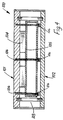
- the heat transfer means may alternatively be suspended from the support plate and such an arrangement is described in Fig. 4.
- a chuck 100 having a support plate 101 and a base plate 102 which is connected to the support plate 101 by a set of pillars 103 having a low thermal expansion coefficient.
- a heat transfer means comprises a set of Peltier cells 104 and a heat sink 105.
- the heat transfer means is secured to the underneath of the support plate 101 by a mounting means, namely a set of fastening screws and spring washers 106. Again, there is a space between the heat transfer means and the base plate 102 to accommodate thermal expansion of the heat transfer means within the rigid structure.
- the pillars 103 which have a low thermal expansion coefficient. Because the heat transfer means is secured to the underneath of the support plate 101 by the fastening screws and spring washers 106, there will always be direct physical contact for heat conduction.
- the pillars 103 may be of a high impedance material, or alternatively may be connected to the base plate or the support plate by high-impedance fasteners. As for the chuck 8, there is always physical contact of the heat transfer means with the support plate, and thermal expansion is downwardly-directed within the space between the heat sink and the base plate.
- the connector between the base and support plates need not necessarily comprise a set of pillars and may be in the form of an annular connector.
- the support plate need not necessarily be plated with gold - it may be of any suitable material plated or non-plated which prevents cross-contamination. It may, for example, be aluminium plated with platinum, or it may be of brass and not plated.
- the mounting means for the heat transfer means internally accommodates expansion and prevents expansion/distortion of the rigid structure by providing a gap between the heat transfer means and the base plate.
- a chuck 119 has a support plate 120, a base plate 121 and InvarTM pillars 122 connecting them together.
- a heat transfer means comprising heating/cooling cells 123 and a base plate 121 are provided, the base plate 121 also acting as a heat sink directly connected to the cells 123.
- the pillars provide a high electrical impedance by way of ceramic washers 124.
- the rigid structure comprises the support plate 120, the pillars 122, and the outer walls of the base plate 121, the latter having connecting means namely screw-holes for connection to the inspection station.
- the top central part of the base plate 121 is deformable and accommodates expansion of the cells 123 as shown by interrupted lines without affecting the rigid structure.
- the heat transfer means may have a resilient part which transfers heat, but also accommodates expansion of other parts of the heat transfer means.
- the base plate can be totally rigid - both internally and externally.
- Such a part of the heat transfer means may comprise a thermally conductive compressible foam.
- Such a foam may be mounted between thermoelectric cells and the support plate, or between the cells and the base plate.
Landscapes
- Physics & Mathematics (AREA)
- General Physics & Mathematics (AREA)
- Engineering & Computer Science (AREA)
- Environmental & Geological Engineering (AREA)
- General Engineering & Computer Science (AREA)
- Testing Or Measuring Of Semiconductors Or The Like (AREA)
- Testing Of Individual Semiconductor Devices (AREA)
Applications Claiming Priority (2)
| Application Number | Priority Date | Filing Date | Title |
|---|---|---|---|
| IE950353 | 1995-05-16 | ||
| IE950353 | 1995-05-16 |
Publications (2)
| Publication Number | Publication Date |
|---|---|
| EP0743530A2 true EP0743530A2 (de) | 1996-11-20 |
| EP0743530A3 EP0743530A3 (de) | 1997-04-09 |
Family
ID=11040752
Family Applications (1)
| Application Number | Title | Priority Date | Filing Date |
|---|---|---|---|
| EP96650017A Withdrawn EP0743530A3 (de) | 1995-05-16 | 1996-05-16 | Testvorrichtung für elektronische Bauteile |
Country Status (2)
| Country | Link |
|---|---|
| US (1) | US6104203A (de) |
| EP (1) | EP0743530A3 (de) |
Cited By (12)
| Publication number | Priority date | Publication date | Assignee | Title |
|---|---|---|---|---|
| US6019164A (en) * | 1997-12-31 | 2000-02-01 | Temptronic Corporation | Workpiece chuck |
| US6073681A (en) * | 1997-12-31 | 2000-06-13 | Temptronic Corporation | Workpiece chuck |
| US6328096B1 (en) | 1997-12-31 | 2001-12-11 | Temptronic Corporation | Workpiece chuck |
| US6415858B1 (en) | 1997-12-31 | 2002-07-09 | Temptronic Corporation | Temperature control system for a workpiece chuck |
| US6583638B2 (en) | 1999-01-26 | 2003-06-24 | Trio-Tech International | Temperature-controlled semiconductor wafer chuck system |
| EP1154275A3 (de) * | 2000-05-12 | 2003-10-29 | Delaware Capital Formation, Inc. | Leiterplatten-BGA-Testvorrichtung |
| EP0915499A3 (de) * | 1997-11-05 | 2004-06-02 | Tokyo Electron Limited | Halbleiterscheibenhaltevorrichtung und Halbleiterscheibenlageraum |
| US6745575B2 (en) | 2002-07-11 | 2004-06-08 | Temptronic Corporation | Workpiece chuck with temperature control assembly having spacers between layers providing clearance for thermoelectric modules |
| US6866094B2 (en) | 1997-12-31 | 2005-03-15 | Temptronic Corporation | Temperature-controlled chuck with recovery of circulating temperature control fluid |
| US6886347B2 (en) | 2002-07-11 | 2005-05-03 | Temptronic Corporation | Workpiece chuck with temperature control assembly having spacers between layers providing clearance for thermoelectric modules |
| EP1123639A4 (de) * | 1998-09-25 | 2007-11-14 | Aehr Test Systems | Thermische testträgerplatte und einbrennen auf platinebene und entsprechendes verfahren |
| CN100376896C (zh) * | 2001-07-26 | 2008-03-26 | 特拉华资本形成公司 | 电路板上的bga试验器 |
Families Citing this family (29)
| Publication number | Priority date | Publication date | Assignee | Title |
|---|---|---|---|---|
| US5345170A (en) | 1992-06-11 | 1994-09-06 | Cascade Microtech, Inc. | Wafer probe station having integrated guarding, Kelvin connection and shielding systems |
| US6380751B2 (en) | 1992-06-11 | 2002-04-30 | Cascade Microtech, Inc. | Wafer probe station having environment control enclosure |
| US5561377A (en) | 1995-04-14 | 1996-10-01 | Cascade Microtech, Inc. | System for evaluating probing networks |
| US6002263A (en) | 1997-06-06 | 1999-12-14 | Cascade Microtech, Inc. | Probe station having inner and outer shielding |
| US6445202B1 (en) * | 1999-06-30 | 2002-09-03 | Cascade Microtech, Inc. | Probe station thermal chuck with shielding for capacitive current |
| KR100373159B1 (ko) * | 1999-11-09 | 2003-02-25 | 주식회사 하이닉스반도체 | 반도체 소자의 캐패시터 제조방법 |
| US6965226B2 (en) | 2000-09-05 | 2005-11-15 | Cascade Microtech, Inc. | Chuck for holding a device under test |
| US6914423B2 (en) | 2000-09-05 | 2005-07-05 | Cascade Microtech, Inc. | Probe station |
| WO2003020467A1 (en) | 2001-08-31 | 2003-03-13 | Cascade Microtech, Inc. | Optical testing device |
| US6777964B2 (en) | 2002-01-25 | 2004-08-17 | Cascade Microtech, Inc. | Probe station |
| US6819131B2 (en) * | 2002-07-11 | 2004-11-16 | Motorola, Inc. | Passive, grease-free cooled device fixtures |
| US6847219B1 (en) | 2002-11-08 | 2005-01-25 | Cascade Microtech, Inc. | Probe station with low noise characteristics |
| US7250779B2 (en) | 2002-11-25 | 2007-07-31 | Cascade Microtech, Inc. | Probe station with low inductance path |
| US6861856B2 (en) | 2002-12-13 | 2005-03-01 | Cascade Microtech, Inc. | Guarded tub enclosure |
| US7221172B2 (en) | 2003-05-06 | 2007-05-22 | Cascade Microtech, Inc. | Switched suspended conductor and connection |
| US7492172B2 (en) | 2003-05-23 | 2009-02-17 | Cascade Microtech, Inc. | Chuck for holding a device under test |
| US7250626B2 (en) | 2003-10-22 | 2007-07-31 | Cascade Microtech, Inc. | Probe testing structure |
| US7187188B2 (en) | 2003-12-24 | 2007-03-06 | Cascade Microtech, Inc. | Chuck with integrated wafer support |
| JP2008502167A (ja) | 2004-06-07 | 2008-01-24 | カスケード マイクロテック インコーポレイテッド | 熱光学チャック |
| US7330041B2 (en) | 2004-06-14 | 2008-02-12 | Cascade Microtech, Inc. | Localizing a temperature of a device for testing |
| US7656172B2 (en) | 2005-01-31 | 2010-02-02 | Cascade Microtech, Inc. | System for testing semiconductors |
| US7535247B2 (en) | 2005-01-31 | 2009-05-19 | Cascade Microtech, Inc. | Interface for testing semiconductors |
| US20070283709A1 (en) * | 2006-06-09 | 2007-12-13 | Veeco Instruments Inc. | Apparatus and methods for managing the temperature of a substrate in a high vacuum processing system |
| CN100567994C (zh) * | 2006-11-03 | 2009-12-09 | 捷智科技股份有限公司 | 在线测试机具 |
| US8319503B2 (en) | 2008-11-24 | 2012-11-27 | Cascade Microtech, Inc. | Test apparatus for measuring a characteristic of a device under test |
| WO2011159390A1 (en) | 2010-06-07 | 2011-12-22 | Cascade Microtech, Inc. | High voltage chuck for a probe station |
| US9244107B2 (en) * | 2012-11-12 | 2016-01-26 | Marvell World Trade Ltd. | Heat sink blade pack for device under test testing |
| US10739397B2 (en) * | 2017-05-10 | 2020-08-11 | International Business Machines Corporation | Accelerated wafer testing using non-destructive and localized stress |
| JP7162500B2 (ja) * | 2018-11-09 | 2022-10-28 | 株式会社Kelk | 温調装置 |
Family Cites Families (11)
| Publication number | Priority date | Publication date | Assignee | Title |
|---|---|---|---|---|
| DE3263256D1 (en) * | 1981-07-08 | 1985-05-30 | Fujitsu Ltd | Device for testing semiconductor devices at a high temperature |
| US4491173A (en) * | 1982-05-28 | 1985-01-01 | Temptronic Corporation | Rotatable inspection table |
| US4567432A (en) * | 1983-06-09 | 1986-01-28 | Texas Instruments Incorporated | Apparatus for testing integrated circuits |
| US4791364A (en) * | 1985-08-20 | 1988-12-13 | Thermonics Incorporated | Thermal fixture for testing integrated circuits |
| US4872835A (en) * | 1986-07-24 | 1989-10-10 | Hewlett-Packard Company | Hot chuck assembly for integrated circuit wafers |
| US5084671A (en) * | 1987-09-02 | 1992-01-28 | Tokyo Electron Limited | Electric probing-test machine having a cooling system |
| US4870355A (en) * | 1988-01-11 | 1989-09-26 | Thermonics Incorporated | Thermal fixture for testing integrated circuits |
| US5001423A (en) * | 1990-01-24 | 1991-03-19 | International Business Machines Corporation | Dry interface thermal chuck temperature control system for semiconductor wafer testing |
| US5164661A (en) * | 1991-05-31 | 1992-11-17 | Ej Systems, Inc. | Thermal control system for a semi-conductor burn-in |
| US5420521A (en) * | 1992-10-27 | 1995-05-30 | Ej Systems, Inc. | Burn-in module |
| DE69533910T2 (de) * | 1994-03-31 | 2005-12-15 | Tokyo Electron Ltd. | Messfühlersystem und Messverfahren |
-
1996
- 1996-05-16 EP EP96650017A patent/EP0743530A3/de not_active Withdrawn
- 1996-05-16 US US08/648,614 patent/US6104203A/en not_active Expired - Fee Related
Cited By (16)
| Publication number | Priority date | Publication date | Assignee | Title |
|---|---|---|---|---|
| EP0915499A3 (de) * | 1997-11-05 | 2004-06-02 | Tokyo Electron Limited | Halbleiterscheibenhaltevorrichtung und Halbleiterscheibenlageraum |
| US6073681A (en) * | 1997-12-31 | 2000-06-13 | Temptronic Corporation | Workpiece chuck |
| US6328096B1 (en) | 1997-12-31 | 2001-12-11 | Temptronic Corporation | Workpiece chuck |
| US6415858B1 (en) | 1997-12-31 | 2002-07-09 | Temptronic Corporation | Temperature control system for a workpiece chuck |
| US6505478B1 (en) | 1997-12-31 | 2003-01-14 | Temptronic Corporation | Heat exchanger having sloped deflection surface for directing refrigerant |
| US6540014B2 (en) | 1997-12-31 | 2003-04-01 | Temptronic Corporation | Workpiece chuck |
| US6019164A (en) * | 1997-12-31 | 2000-02-01 | Temptronic Corporation | Workpiece chuck |
| US7331097B2 (en) | 1997-12-31 | 2008-02-19 | Temptronic Corporation | Method of manufacturing a workpiece chuck |
| US6866094B2 (en) | 1997-12-31 | 2005-03-15 | Temptronic Corporation | Temperature-controlled chuck with recovery of circulating temperature control fluid |
| WO2000004570A3 (en) * | 1998-07-14 | 2000-04-20 | Temptronic Corp | Workpiece chuck |
| EP1123639A4 (de) * | 1998-09-25 | 2007-11-14 | Aehr Test Systems | Thermische testträgerplatte und einbrennen auf platinebene und entsprechendes verfahren |
| US6583638B2 (en) | 1999-01-26 | 2003-06-24 | Trio-Tech International | Temperature-controlled semiconductor wafer chuck system |
| EP1154275A3 (de) * | 2000-05-12 | 2003-10-29 | Delaware Capital Formation, Inc. | Leiterplatten-BGA-Testvorrichtung |
| CN100376896C (zh) * | 2001-07-26 | 2008-03-26 | 特拉华资本形成公司 | 电路板上的bga试验器 |
| US6886347B2 (en) | 2002-07-11 | 2005-05-03 | Temptronic Corporation | Workpiece chuck with temperature control assembly having spacers between layers providing clearance for thermoelectric modules |
| US6745575B2 (en) | 2002-07-11 | 2004-06-08 | Temptronic Corporation | Workpiece chuck with temperature control assembly having spacers between layers providing clearance for thermoelectric modules |
Also Published As
| Publication number | Publication date |
|---|---|
| US6104203A (en) | 2000-08-15 |
| EP0743530A3 (de) | 1997-04-09 |
Similar Documents
| Publication | Publication Date | Title |
|---|---|---|
| US6104203A (en) | Test apparatus for electronic components | |
| US11302556B2 (en) | Apparatus for spatial and temporal control of temperature on a substrate | |
| US10062597B2 (en) | High voltage chuck for a probe station | |
| US6328096B1 (en) | Workpiece chuck | |
| EP1852907B1 (de) | Methode zum Halten und Bearbeiten von SOS oder SOI Halbleiterscheiben | |
| US7352168B2 (en) | Chuck for holding a device under test | |
| US6534751B2 (en) | Wafer heating apparatus and ceramic heater, and method for producing the same | |
| CN103370778B (zh) | 具有加热器与快速温度变化的基板支撑件 | |
| US6583638B2 (en) | Temperature-controlled semiconductor wafer chuck system | |
| US20030213793A1 (en) | Wafer chuck having thermal plate with interleaved heating and cooling elements, interchangeable top surface assemblies and hard coated layer surfaces | |
| US20090032522A1 (en) | Zone control heater plate for track lithography systems | |
| WO2007019072A2 (en) | Vertical probe card and air cooled probe head system | |
| US5901030A (en) | Electrostatic chuck employing thermoelectric cooling |
Legal Events
| Date | Code | Title | Description |
|---|---|---|---|
| PUAI | Public reference made under article 153(3) epc to a published international application that has entered the european phase |
Free format text: ORIGINAL CODE: 0009012 |
|
| AK | Designated contracting states |
Kind code of ref document: A2 Designated state(s): DE GB |
|
| PUAL | Search report despatched |
Free format text: ORIGINAL CODE: 0009013 |
|
| AK | Designated contracting states |
Kind code of ref document: A3 Designated state(s): DE GB |
|
| 17P | Request for examination filed |
Effective date: 19970915 |
|
| 17Q | First examination report despatched |
Effective date: 20020621 |
|
| STAA | Information on the status of an ep patent application or granted ep patent |
Free format text: STATUS: THE APPLICATION IS DEEMED TO BE WITHDRAWN |
|
| 18D | Application deemed to be withdrawn |
Effective date: 20021101 |