EP0743580B1 - Kürzestzeit Alternativzielplaner - Google Patents
Kürzestzeit Alternativzielplaner Download PDFInfo
- Publication number
- EP0743580B1 EP0743580B1 EP95203125A EP95203125A EP0743580B1 EP 0743580 B1 EP0743580 B1 EP 0743580B1 EP 95203125 A EP95203125 A EP 95203125A EP 95203125 A EP95203125 A EP 95203125A EP 0743580 B1 EP0743580 B1 EP 0743580B1
- Authority
- EP
- European Patent Office
- Prior art keywords
- aircraft
- alternate
- destinations
- pilot
- diversion
- Prior art date
- Legal status (The legal status is an assumption and is not a legal conclusion. Google has not performed a legal analysis and makes no representation as to the accuracy of the status listed.)
- Revoked
Links
- 238000000034 method Methods 0.000 claims description 36
- 230000000977 initiatory effect Effects 0.000 claims 1
- 238000007726 management method Methods 0.000 description 41
- 239000000446 fuel Substances 0.000 description 32
- 230000006870 function Effects 0.000 description 11
- 238000010586 diagram Methods 0.000 description 9
- 230000008859 change Effects 0.000 description 8
- 230000004048 modification Effects 0.000 description 8
- 238000012986 modification Methods 0.000 description 8
- 230000007704 transition Effects 0.000 description 6
- 238000004364 calculation method Methods 0.000 description 5
- 230000000881 depressing effect Effects 0.000 description 5
- 230000000007 visual effect Effects 0.000 description 5
- 230000009194 climbing Effects 0.000 description 3
- 238000013278 delphi method Methods 0.000 description 3
- 230000000994 depressogenic effect Effects 0.000 description 3
- 230000007613 environmental effect Effects 0.000 description 3
- 230000004044 response Effects 0.000 description 3
- 238000010926 purge Methods 0.000 description 2
- 238000012546 transfer Methods 0.000 description 2
- 238000013459 approach Methods 0.000 description 1
- 230000005540 biological transmission Effects 0.000 description 1
- AGOYDEPGAOXOCK-KCBOHYOISA-N clarithromycin Chemical compound O([C@@H]1[C@@H](C)C(=O)O[C@@H]([C@@]([C@H](O)[C@@H](C)C(=O)[C@H](C)C[C@](C)([C@H](O[C@H]2[C@@H]([C@H](C[C@@H](C)O2)N(C)C)O)[C@H]1C)OC)(C)O)CC)[C@H]1C[C@@](C)(OC)[C@@H](O)[C@H](C)O1 AGOYDEPGAOXOCK-KCBOHYOISA-N 0.000 description 1
- 239000012141 concentrate Substances 0.000 description 1
- 230000007423 decrease Effects 0.000 description 1
- 238000012217 deletion Methods 0.000 description 1
- 230000037430 deletion Effects 0.000 description 1
- 230000001419 dependent effect Effects 0.000 description 1
- 230000000694 effects Effects 0.000 description 1
- 238000005259 measurement Methods 0.000 description 1
- 230000008520 organization Effects 0.000 description 1
- 230000000737 periodic effect Effects 0.000 description 1
- 230000008569 process Effects 0.000 description 1
- 238000012552 review Methods 0.000 description 1
Images








Classifications
-
- G—PHYSICS
- G08—SIGNALLING
- G08G—TRAFFIC CONTROL SYSTEMS
- G08G5/00—Traffic control systems for aircraft
- G08G5/30—Flight plan management
- G08G5/34—Flight plan management for flight plan modification
-
- G—PHYSICS
- G01—MEASURING; TESTING
- G01C—MEASURING DISTANCES, LEVELS OR BEARINGS; SURVEYING; NAVIGATION; GYROSCOPIC INSTRUMENTS; PHOTOGRAMMETRY OR VIDEOGRAMMETRY
- G01C23/00—Combined instruments indicating more than one navigational value, e.g. for aircraft; Combined measuring devices for measuring two or more variables of movement, e.g. distance, speed or acceleration
-
- G—PHYSICS
- G05—CONTROLLING; REGULATING
- G05D—SYSTEMS FOR CONTROLLING OR REGULATING NON-ELECTRIC VARIABLES
- G05D1/00—Control of position, course, altitude or attitude of land, water, air or space vehicles, e.g. using automatic pilots
- G05D1/0055—Control of position, course, altitude or attitude of land, water, air or space vehicles, e.g. using automatic pilots with safety arrangements
-
- G—PHYSICS
- G08—SIGNALLING
- G08G—TRAFFIC CONTROL SYSTEMS
- G08G5/00—Traffic control systems for aircraft
- G08G5/20—Arrangements for acquiring, generating, sharing or displaying traffic information
- G08G5/26—Transmission of traffic-related information between aircraft and ground stations
-
- G—PHYSICS
- G08—SIGNALLING
- G08G—TRAFFIC CONTROL SYSTEMS
- G08G5/00—Traffic control systems for aircraft
- G08G5/50—Navigation or guidance aids
- G08G5/54—Navigation or guidance aids for approach or landing
-
- G—PHYSICS
- G08—SIGNALLING
- G08G—TRAFFIC CONTROL SYSTEMS
- G08G5/00—Traffic control systems for aircraft
- G08G5/50—Navigation or guidance aids
- G08G5/55—Navigation or guidance aids for a single aircraft
-
- G—PHYSICS
- G08—SIGNALLING
- G08G—TRAFFIC CONTROL SYSTEMS
- G08G5/00—Traffic control systems for aircraft
- G08G5/50—Navigation or guidance aids
- G08G5/58—Navigation or guidance aids for emergency situations, e.g. hijacking or bird strikes
Definitions
- the present invention relates to flight management systems for aircraft and, more particularly, to flight management systems that provide emergency landing information to a pilot.
- Alternate destination planners currently incorporated in aircraft generally contain a database of airports from which a list of alternate destinations at which the aircraft can land may be selected and displayed. In addition to listing the alternate landing locations, alternate destination planners typically provide arrival data such as the distance to each alternate destination, the estimated time until arrival at each alternate destination, and the estimated amount of fuel remaining upon landing at each alternate destination.
- the alternate landing destination information is usually only used in emergency situations that would prevent the aircraft from landing at the intended destination such as inclement weather of the intended destination or an onboard emergency.
- the pilot of the aircraft is apprised by the alternate destination planner of a number of alternate destinations to which the aircraft can be diverted.
- the decision of which destination to select is ultimately made by the pilot, who may base his or her decision upon a number of factors, including the flight time to the alternate destination, the emergency facilities contained at the alternate destination, and the length of the runway at the alternate destination.
- Providing the pilot of the aircraft an onboard list of alternate destinations is more efficient than having the pilot contact air traffic control to determine the nearest alternate destination.
- the alternate destination planner provides the pilot with sufficient onboard information to make an autonomous decision during flight before communicating the decision to air traffic control.
- the FMC system modification displays to the pilot the distance between the aircraft's present position and the alternate destination, an estimated time of arrival (ETA) at the alternate destination, and an estimate of the fuel remaining onboard the aircraft if the aircraft were to land at the alternate destination.
- the ETA and remaining fuel are calculated by estimating the flight path that the aircraft would have to take from the current position to the alternate airport.
- a rough estimation technique is used to calculate both the ETA and fuel remaining.
- the displayed trip information has generally less accuracy than would be normally be displayed by the flight management computer when estimating and displaying the time to and fuel remaining at the intended destination of the aircraft.
- the flight management computer generates a series of screens on a control and display unit (CDU) which allow the pilot to compare the ETA and remaining fuel for a number of different alternate destinations. If a pilot were actually to divert to one of the alternate destinations, however, the routing information to that destination has to be programmed into the flight management computer by the pilot.
- CDU control and display unit
- the programming procedure takes a significant amount of time and effort by the pilot when the pilot's attention may be more effectively used elsewhere. For example, in the preferred embodiment of the flight management computer disclosed in the '186 patent, the following steps must be followed to divert an aircraft to an alternate destination.
- the pilot must select a RTE LEGS page, and enter any alternate waypoints into the active flight plan currently stored in the computer.
- the pilot must select a RTE page and enter the alternate destination into the active flight plan. Once the waypoints and destination have been stored in the flight management computer, any changes to the vertical profile of the airplane must be made by the pilot by accessing the CLB (climb), CRZ (cruise), or DES (descent) page.
- the pilot must select a VNAV page and select engine-out performance for the aircraft. Once all changes have been made, the modified flight plan must then be executed.
- the alternate destination planner disclosed in the '186 patent is that the estimate of the ETA and remaining fuel provided by the flight management computer has limited accuracy due to the estimation procedure used to calculate the arrival data.
- the alternate destination planner of the '186 patent assumes a direct flight path to the alternate destination, a constant speed equal to the airplane's current speed, and certain environmental conditions such as the external temperature.
- the requisite amount of accuracy is provided to the pilot by an alternate destination planner using theses assumptions, in extreme cases a more accurate estimate of the trip information may prove to be invaluable to a pilot.
- EOPS extended-range twin-engine operation
- a further limitation of the alternate destination planner disclosed in the '186 patent is that it provides limited routing options between the current position and the selected alternate destination.
- the alternate destination planner assumes that a direct or missed approach course will be taken from the aircraft's current position to the alternate destination.
- a direct course is the most common routing that would occur when flying to an alternate destination, there are a number of additional routing options that are possible and desirable for a pilot to follow. It will therefore be appreciated that an alternate destination planner that allowed a pilot to select a number of different routing paths between the aircraft's current position and the alternate destination would allow the pilot greater flexibility in planning and when it became necessary to divert to the alternate destination.
- US A 5 398 186 discloses a previous generation alternate destination planner for an aircraft.
- This destination planner provides a pilot of an aircraft with a list of alternate landing destinations so that a pilot can view and evaluate simultaneously.
- a diversion to an alternate destination however a significant amount of effort by the pilot is required.
- the pilot choses the alternate destination that best suits the needs of the situation.
- the pilot has to manually program the routing information to that destination into the flight management computer.
- the pilot must program the desired alternate destination into the flight management computer, which takes a significant amount of time and effort by the pilot when the pilot's attention may be more effectively used elsewhere.
- the present invention is directed to an improved alternate destination planner within a flight management computer that reduces the time and effort required by a pilot to divert an aircraft to an alternate destination.
- the present invention is a modification to an aircraft's flight management computer (FMC) system to incorporate an improved alternate destination planner in the FMC.
- the alternate destination planner disclosed herein provides a pilot with a list of alternate landing destinations based on a navigational database of available landing sites stored in the memory of the FMC, or based on a list of alternate destinations transmitted to the aircraft from a ground station. For each alternate destination, the alternate destination planner advises the pilot of an expected time of arrival (ETA) and an amount of fuel remaining upon arrival at the alternate destination.
- ETA expected time of arrival
- the displayed arrival data allows the pilot to make an informed decision about which alternate landing destination to choose in the event of an emergency requiring diversion from the intended destination.
- the alternate destination planner automatically lists the alternate destinations according to the ETA at each of the destinations.
- the planner disclosed herein takes into account the user-modifiable parameters of aircraft altitude, aircraft speed, wind direction and speed, outside air temperature, and selected routing option.
- the estimates of the ETA and remaining fuel are automatically recalculated and redisplayed based on the specific parameter defined by the pilot.
- the alternate destination planner disclosed herein therefore provides the pilot with a highly accurate estimate of the arrival data corresponding to each alternate destination, from which the pilot can select the most appropriate flight path diversion during an emergency.
- an offset route is a route that parallels the direct route to the alternate destination, but is offset to the left or right of the direct route by a desired number of nautical miles.
- An overhead route allows a pilot to continue along the original flight plan to a specified waypoint, and then to fly directly from the point overhead the waypoint to the selected alternate destination. The three routing options allow a pilot greater flexibility when diverting to the alternate destination.
- the selection and diversion of an aircraft to an alternate destination is automatically performed using a minimal amount of pilot input.
- the pilot merely has to press two keys to automatically select an alternate destination and reprogram the flight management computer with the flight plan to the selected destination.
- the pilot may also indicate during such a diversion when one of the aircraft's engines has failed.
- the alternate destination planner After receiving notification of the engine failure, the alternate destination planner automatically recomputes the ETA and remaining fuel for the alternate destination based on the limited performance of the aircraft.
- data may be transmitted from a ground station to the alternate destination planner in order to provide accurate conditions for estimation of the ETA and remaining fuel for each alternate destination.
- An airline may also transmit data to the aircraft which provide a list of alternate destinations as well as a desired routing to those destinations.
- the capability of the alternate destination planner to receive and incorporate updated data into its calculations ensures that accurate diversion information can be continuously provided to the pilot.
- the FMC generates a visual indication of the location of the alternate airports on a navigation display.
- the visual indication of the location of the alternate destinations with respect to the current aircraft position and the active flight plan route allows the pilot to quickly judge the distance and orientation to a number of different alternate airports.
- the display allows the pilot to more rapidly select the airport to divert to minimizing the amount of time that the diversion takes when an emergency occurs.
- the above features of the alternate destination planner allow a pilot to quickly and efficiently divert an aircraft to an alternate destination during an emergency situation.
- the improved visual identification of the location of the alternate destinations, as well as the more accurate estimation of the ETA and remaining fuel for each alternate destination improves the decision-making of the pilot.
- the capability or preprogramming the alternate destination planner with specific diversion parameters also allows the pilot and the airline a flexible means to tailor their diversion response to specific emergency situations.
- the alternate destination planner disclosed herein therefore allows a pilot to respond to emergency situations in an efficient and expeditious manner.
- FIGURE 1 is a pictorial diagram of the face of a control and display unit (CDU) 30 that is typically used in commercial aircraft as an interface to a flight management computer system.
- the flight management computer typically stores a predetermined flight plan in memory, and tracks the current location of the aircraft along the flight plan from the originating airport to the destination airport. To accurately monitor the aircraft's location, the flight management computer receives data from a variety of aircraft subsystems and sensors that are well known in the aircraft art. Flight management computers and CDUs are well known in the aircraft art, so :he following disclosure will not discuss the specific implementation of the flight management computer and CDU except as required to disclose the present invention. Further details of the cooperation of the flight management computer and the CDU may be found in U.S. Patent No. 5,398,186, entitled "Alternate Destination Predictor for Aircraft".
- the CDU acts as an interface to the flight management computer, and includes a display 32 and a keyboard 34 to allow the aircraft pilot to selectively view and manipulate navigation and other data.
- the display 32 of the CDU 30 includes a central display area 36 in which data is displayed to the pilot.
- Above the central display area 36 is an area 36a in which a data status block is displayed, an area 36b in which a title of the screen is displayed, and an area 36c on which a page number of the screen is displayed.
- two sets of keys are disposed on either side of the central area of the display.
- a first set of keys is disposed on the left side of the display area 36, and a second set of keys, identified as 1R through 6R, is disposed on the right side.
- Each key corresponds to a display line which makes up the central display area 36 of the CDU. Pressing one of the keys on the left side or the right side of the display area typically implements a function that is displayed in the central area 36 immediately adjacent to the key that is depressed.
- a pilot may also enter data into the CDU using a set of alphanumeric keys 34 Data entered by the pilot is first displayed in a scratch pad area 38 located beneath the central display area 36.
- the pilot may move the data to a particular line of the central display area 36 by depressing one of the left keys, 1L through 6L, or right keys, 1R through 6R.
- the data contained in the scratch pad area is then typically moved to a position adjacent to the key that was depressed.
- a plurality of function keys are also provided to directly implement predefined functions.
- a pair of keys 40 denoted next page and previous page allow the pilot to view the next screen of data or to review a previous screen of data displayed on the CDU 30.
- Two function keys are provided to access details of active or alternate route information.
- An RTE key 42 allows a pilot to view details about the active flight plan
- an LEGS key 44 allows the user to select and view data about a particular leg in the predefined or alternate flight plan.
- two function keys are of particular interest to the present invention.
- An ALTN key 46 is used to access an alternate destination summary page. A pilot pressing the ALTN key directly jumps to a family of ALTN data pages, the first page containing a list of alternate destinations surrounding the current position of the aircraft.
- An EXEC key 48 is also provided to confirm execution of certain user selected functions. In particular, when performing a diversion to an alternate destination, the EXEC key is used by the pilot to implement a change in course from the active flight plan.
- the flight management computer is connected to the CDU to aid a pilot in navigating to an intended destination airport. If the aircraft is unable to land at the intended destination, for example because of inclement weather, engine failure, or a medical emergency onboard the aircraft, a pilot must select and divert to an alternate destination.
- the alternate destination may be a commercial airport, a military airport, or any other facility having sufficient area for the aircraft to land.
- the flight management computer is programmed with an alternate destination planner.
- the flight management computer system is modified to compute and display for a plurality of alternate destinations the estimated time of arrival (ETA) and remaining fuel if the aircraft were to fly from the current position to each of the destinations.
- ETA estimated time of arrival
- the pilot may determine the appropriate alternate destination to which the aircraft should be diverted.
- the alternate destination planner disclosed herein facilitates the diversion by minimizing the amount of data manipulation required by the pilot, and by providing more accurate information on which the pilot may base their decision.
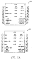
- a pilot When a pilot is initially presented with an emergency situation, or when the pilot desires to preevaluate alternate destinations to which the aircraft might divert, the pilot presses ALTN key 46 on the CDU function key pad. Upon depressing the ALTN key, a data screen providing a summary of alternate destinations is automatically displayed on central area 36 of display 32. A series of screens representative of the data screens that may be accessed by the pilot on the CDU is depicted in FIGURES 2A and 2B. Upon pressing the ALTN key, a first screen 50 is displayed to the pilot. First screen 50 provides a summary of the nearest alternate destinations within range of the aircraft based on the current aircraft position and remaining fuel.
- the first four lines of display area 36 provide the closest four alternate destinations, automatically listed according to the time that it would take to fly to each particular alternate destination. The first entry on the list is therefore always the closest in time alternate destination.
- the closest in time alternate destinations are identified by their International Civil Aviation Organization (ICAO) identifiers, and include airports at KRNO (Reno, Nevada), KTLV (Las Vegas, Nevada), KSMF (Sacramento, California), KLAX (Los Angeles, California).
- IICAO International Civil Aviation Organization
- the alternate destination planner In addition to automatically identifying the nearest alternate destinations by time, the alternate destination planner also calculates and displays an estimated time of arrival (ETA) at the alternate airport, and an amount of remaining fuel if the aircraft were to fly from the current position to the alternate airport via a selected routing option.
- the ETA and remaining fuel calculated by the alternate destination planner will hereinafter be referred to collectively as the arrival data.
- each line on the screen containing an alternate destination includes the alphanumeric identifier for the destination, the ETA, and the fuel remaining.
- the method of determining the four closest alternate destinations will be discussed in further detail below with respect to FIGURE 3, and the method of calculating the arrival data will be discussed below with respect to FIGURES 4A-4G.
- the pilot may also manually include or inhibit an alternate destination in the summary list.
- the pilot keys the ICAO identifier in the scratch pad, and depresses one of the keys 1L through 4L to transfer the manually entered destination into the destination list.
- the alternate destination planner will automatically calculate and display the arrival data for the manually entered destination.
- the alternate destination planner will also sort the summary list of alternate destinations so that the manually entered destination will appear in proper order of ETA. Once a destination is manually entered, it will remain in the summary list until deletion by the pilot. The other alternate destinations will change, however, as other alternate destinations are brought within closer ETA proximity to the position of the aircraft.
- a pilot enters the ICAO identifier of the alternate destination and depresses key 5R, labeled ALTN INHIB, to transfer the manually entered destination into the inhibit list.
- key 5R labeled ALTN INHIB
- adjacent key 5R are two fields that make up the inhibit list. Each field can contain an ICAO identifier.
- the pilot may obtain more information about a particular alternate destination by depressing a corresponding key 1R through 4R. If, for example, the pilot were to press the 1R key to obtain more information about the alternate destination KRNO, a second screen 52 would be displayed on the CDU.
- the second screen 52 provides detailed information about the routing options for diverting from the active flight plan to the alternate destination.
- the second screen also provides a list of operating conditions used to calculate the arrival data for that particular alternate destination.
- a list of three routing options 54 is provided to allow the pilot to specify the type of routing that will occur when the aircraft diverts from the active flight plan to a selected alternate destination.
- the first routing option corresponding to key 1L, is direct routing. When direct routing is selected, the aircraft is directly routed from the location of the aircraft when the diversion occurs to the selected alternate destination.
- the direct routing option is the default routing option automatically selected by the alternate destination planner, the selection of which is indicated by the characters ⁇ SEL> following the option on second screen 52.
- the second routing option is offset routing, corresponding to the 2L key.
- the aircraft When offset routing is selected, at the diversion point the aircraft will fly a path parallel to the active flight plan, but offset to the left or to the right of the active flight plan by a specified number of nautical miles.
- the amount of offset selected by the pilot is indicated by an alphanumeric identifier "L" or “R,” indicating “left” or “right,” and a number representing the nautical miles of the offset.
- the offset is currently set to L10, indicating a left offset of 10 nautical miles. In a preferred embodiment of the invention, the offset may extend up to 99 nautical miles.
- the aircraft At a point in the offset continuation of the aircraft along the original flight plan, it is presumed that the aircraft will leave the offset path and fly a direct path to the alternate destination.
- the offset maneuver is therefore used to temporarily remove an aircraft from a heavy air traffic route before the direct diversion to the alternate destination occurs.
- the third routing option is overhead routing, corresponding to the 3L key.
- overhead routing is selected, the aircraft will continue along the active flight plan to a selected waypoint. Upon reaching the selected waypoint, the aircraft then diverts from the active flight plan and flies directly to the alternate destination.
- the waypoint at which the aircraft diverts from the active flight plan is indicated by the ICAO identifier for the waypoint.
- the selected waypoint is KSEA, corresponding to the airport at Seattle, Washington.
- the default waypoint at which the aircraft leaves the active flight plan is the next waypoint along the active flight plan from the aircraft's current position. Alternatively, the pilot may specify the waypoint by entering in the alphanumeric code for the waypoint.
- the pilot may select which of the three routing options 54 to use in the event of a diversion by pressing the appropriate key, 1L-3L, adjacent the routing option.
- the pilot may also vary the desired offset or waypoint in the routing option. For example, as shown by the series of keystrokes in FIGURE 2A, if the pilot desired to change the offset from left 10 nautical miles to right 20 nautical miles, the pilot would use the alphanumeric keypad to enter R-2-0- followed by pressing the 2L key twice. These keystrokes will initially display R20 in scratch pad area 38 of the CDU. Pressing the 2L key the first time moves the scratch pad data to a position adjacent the 2L key, changing the offset from L10 to R20.
- the selection of a routing option is a global selection that applies to all four of the alternate destinations displayed on first screen 50. That is, once a pilot has selected a routing option, a diversion to any of the four alternate destinations will take place along the selected routing option. If overhead routing is globally selected, however, each alternate destination may have a different waypoint specified at which the diversion from the active flight plan occurs.
- second screen 52 also displays a list of operating conditions 56 that are used by the alternate destination planner to calculate the ETA and fuel remaining at each of the alternate destinations.
- the first operating condition is the altitude of the aircraft to be used during diversion.
- the altitude of the aircraft may be entered by the pilot in either of two formats that are automatically recognized by the alternate destination planner. In an altitude format, the pilot enters the altitude of the aircraft in feet. For example, the pilot may enter "12000" to indicate that during diversion the aircraft should operate at 12,000 feet. In a second flight level format, the pilot may enter a flight level code indicative of the altitude. For example, the pilot may enter "FL250" to indicate that the aircraft should operate at 25,000 feet.
- the pilot keys the formatted altitude using the alphanumeric key pad of the CDU and then presses the 1R key to move the altitude level to a position on the screen.
- the altitude of the aircraft is globally applied to all alternate destinations. That is, the calculation of the arrival data for all four alternate destinations on first screen 50 is based on the same altitude.
- the second operating condition is the speed of the aircraft at which diversion is to occur.
- the speed of the aircraft may be entered by the pilot in one of several formats.
- the pilot may enter a three-digit airspeed indicative of the aircraft's speed in knots. For example, the pilot may enter "300" to indicate a speed of 300 knots.
- the three-digit airspeed is typically only used to represent a low altitude diversion.
- the pilot may enter a three-digit mach number, indicative of the aircraft's speed as a fraction of the speed of sound. In a preferred embodiment of the invention for subsonic aircraft, the mach number is always a fraction less than one. As shown in second screen 52, for example, the entered speed is mach 0.810.
- the mach number is typically entered by the pilot for a high altitude diversion.
- the pilot may enter an alphanumeric speed code indicative of a certain type of performance.
- the pilot may enter the code "LRC" to represent a long range cruise mode.
- long range cruise mode the alternate destination planner calculates the most fuel efficient speed for the aircraft to fly at given the current weight of the aircraft.
- several other alphanumeric speed codes may be provided, including codes for engine out operation, economy operation, and an airline defined default cruise mode.
- the speed of the aircraft is globally applied to all alternate destinations. That is, the calculation of the arrival data for all four alternate destinations on first screen 50 is based on the same speed.
- the remaining operating conditions are locally defined for each alternate destination.
- the third operating condition corresponds to the wind at the particular alternate destination.
- the pilot enters the value of the wind at the alternate destination by entering a three-digit value indicative of the direction of the wind in degrees, followed by a slash, followed by an up to three-digit value for the wind velocity measured in knots.
- the pilot may enter a wind value of 093/15 to indicate a wind bearing 93° at a velocity of 15 knots.
- a different wind value may be entered by the pilot for each of the alternate destinations displayed on first screen 50.
- the fourth operating condition is the outside air temperature associated with a particular altitude at an alternate destination.
- the format for the outside air temperature is the altitude, followed by a slash, followed by a temperature at the destination in plus or minus degrees Celsius.
- the altitude may be entered in either the altitude format or the flight level format discussed above with respect to the altitude condition. For example, a pilot may enter FL250/-25 to indicate a temperature of -25C° at an altitude of 25,000 feet.
- hyphens are inserted at the appropriate location to indicate the number of characters and appropriate format for each condition.
- a different outside air temperature value may be entered by the pilot for each of the alternate destinations displayed on first screen 50.
- the pilot uses the alphanumeric keypad on the CDU to enter the updated condition using the appropriate format.
- the pilot then presses the appropriate key, 1R-4R, to move the value from the scratch pad to a position adjacent the selected key.
- a pilot may enter a wind bearing 93° at a velocity of 15 knots using the keystrokes 0-9-3-/-1-5.
- the wind data is then transferred from the scratch pad to a position adjacent the 3L key on fourth screen 60.
- typical operating conditions may be included in an airline modifiable information (AMI) file that is stored in the FMC and accessible to the alternate destination planner.
- AMI airline modifiable information
- the AMI file maintains a number of preselected values that the airline company has decided are suitable for describing the flight of the aircraft in the absence of a pilot preference.
- an airline defined aircraft speed and aircraft altitude are typically defined in the AMI file.
- the arrival data is also repeated for the particular alternate destination represented on the screen.
- arrival data As shown on second screen 52, adjacent to key 5R is arrival data showing the estimated time of arrival at KRNO and the amount of fuel remaining upon landing.
- the arrival data displayed on the particular alternate destination screen corresponds to the data that is displayed on first screen 50.
- the arrival data is calculated by the alternate destination planner, and is not modifiable by the pilot.
- FIGURE 3 is a flowchart of a main program 70 incorporated within the alternate destination planner that is used to identify according to flight time the four closest airports to the aircraft's current position.
- the program calculates the ETA and remaining fuel to each alternate destination and displays the alternate destinations, ETAs and remaining fuel on the CDU. Initially, the program enters a loop to search a navigation database contained within the flight management computer and identify suitable alternate destinations in the database.
- flight management computers typically incorporate a database containing a list of all airports and other landing destinations around the world. Although the format may vary, the database typically contains a four-digit destination identifier, a set of coordinates representing the precise latitude and longitude of the destination, and a data field indicating the runway length at the particular destination. Additional data fields containing further information about the facilities at each of the destinations may be included in the navigation database, depending upon the size and complexity of the database incorporated in the flight management computer.
- the main program To search the navigation database, the main program initially loads a destination from the database at a block 72 and, at a decision block 74, examines the destination to determine if the runway is of sufficient length to land the aircraft containing the alternate destination planner.
- a minimum runway length for the particular aircraft is defined by the airline and included in the AMI file stored in the FMC. If the runway at the destination is not of sufficient length, the program returns to block 72 where a new destination is loaded and examined by the program. If the runway is of sufficient length, however, the main program proceeds to a block 76 where the destination is added to a destination list.
- the main program determines if there are any more entries in the navigation database. If the database contains additional entries, the main program returns to a block 72 to examine the next entry in the database. If the entire database has been searched, however, the main program proceeds to a block 80.
- the main program examines the suitable destinations selected from the navigation database to determine the eight closest destinations to the airplane's current position.
- a straight line distance between the airplane's current position and the latitude and longitude of the destination is calculated, and the resulting distances compared to select the eight closest destinations by distance.
- the calculation of the distance between two points identified by latitude and longitude coordinates is well known in the navigation art. It will be appreciated that an additional step may be incorporated in block 80, wherein a direct comparison is made with the latitude and longitude of the current aircraft position to quickly eliminate distant destinations without calculating a straight line distance.
- the main program calculates an ETA to the eight closest destinations.
- a flow chart of an ETA subroutine 100 for calculating the ETA to a given alternate destination is shown in FIGURE 4A.
- the ETA subroutine divides the diversion path into two or three flight segments, depending upon the routing option that is selected.
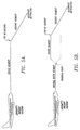
- a diagram of two flight profiles showing the flight segments used by the alternate destination planner to calculate the ETA during diversion from an original flight plan to an alternate destination are shown in FIGURES 5A and 5B.
- the flight profile shown in FIGURE 5A represents the flight profile used by the alternate destination planner when the direct or offset routing options have been selected by the pilot.
- the aircraft initially enters a cruise segment where it maintains a desired altitude and a desired speed.
- the cruise segment extends until the aircraft hits a top of descent point, after which the aircraft begins to descend to the alternate destination.
- the aircraft is presumed to descend along the following predefined descent path:
- FIGURE 5B shows a flight profile used by the alternate destination planner when overhead routing has been selected by the pilot.
- the aircraft continues along the original flight plan until the desired diversion point is reached overhead a waypoint.
- the first segment of the flight is therefore identified as the original route segment.
- the aircraft assumes a flight profile identical to the profile used in direct or offset routing. That is, upon reaching the diversion point, the aircraft enters a cruise segment at a desired speed and a desired altitude. Upon entering the cruise segment, the aircraft will typically ascend or descend to a more efficient altitude from the altitude of the original flight segment. Following the cruise segment, the aircraft reaches a top of descent point where it begins to descend along a predefined descent path to the alternate destination. The length of the descent segment and the top of descent point is calculated in a similar manner to the direct and offset methods described above.
- Block 106 begins a portion of the ETA subroutine where the subroutine calculates the ETE for the cruise segment.
- the ETA subroutine initially calls three nested subroutines to calculate the speed of the aircraft to be used during the cruise segment, the altitude of the aircraft to be used during the cruise segment, and the average wind to be encountered over the cruise segment.
- the ETA subroutine calls a subroutine to determine the speed of the aircraft to be used during the cruise segment, represented by a variable Spd(a).
- a speed subroutine 150 for determining the speed of the aircraft is shown in FIGURE 4B.
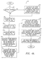
- the routine determines whether there has been a manual speed entry by the pilot. If the pilot has manually entered a speed, the subroutine proceeds to a decision block 154. At decision block 154, the speed subroutine determines if the manual entry is in airspeed or mach format. As discussed above, the current speed may be entered by a pilot in knots or as a fraction of the speed of sound. If the manual entry is in airspeed or mach format, the subroutine proceeds to a block 156 where the variable Spd(a) is set equal to the manually entered value.
- the program proceeds to a series of blocks 158 through 172 which determine the speed based on a number of preprogrammed alphanumeric codes representing a desired air speed. For example, at a decision block 158 the subroutine determines if the manual entry is equal to the characters "EO.” If the manual entry is EO, the subroutine proceeds to a block 160 where it sets the variable Spd(a) equal to a computed engine out speed. Those skilled in the art will recognize that the computed engine out speed is less than the normal flight speed of the aircraft, and is determined by evaluating a number of different factors that are beyond the scope of the present disclosure.
- blocks 162 and 164 represent a branch setting the variable Spd(a) equal to a computed long-range cruising speed if a pilot has manually entered the code "LRC.”
- the long-range cruising speed is the minimum fuel-burn speed for the aircraft over a long-range flight, and is computed using an algorithm that is beyond the scope of this disclosure.
- Blocks 166 and 168 determine whether the pilot has entered the code for an engine out long-range cruising speed
- blocks 170 and 172 determine whether the pilot has entered the code for a company defined speed stored in the memory of the flight management computer. It will be appreciated that the number and alphanumeric codes represented in blocks 158 and 172 may be expanded or reduced to include additional or fewer codes indicative of a desired speed.
- the speed subroutine proceeds to a decision block 174 where the altitude of the aircraft is determined. It will be appreciated that in the United States, the FAA has mandated that under a certain altitude commercial aircraft must operate below a maximum speed. If the altitude of the aircraft indicates it is below the mandated speed transition level, at a block 176 the variable Spd(a) is set equal to the maximum speed below the transition altitude minus 10 knots. It will be appreciated that in other countries having different maximum speeds below a certain altitude, the variable Spd(a) will be set accordingly.
- the speed subroutine proceeds to a decision block 178 where the subroutine determines whether there is a speed value stored in the AMI file. If there is a stored speed value in the AMI file, the subroutine proceeds to a block 180 where the variable Spd(a) is set equal to the stored AMI value.
- the subroutine proceeds to a block 182 where the variable Spd(a) is set equal to a computed economy speed.
- the economy speed is determined based on a variety of environmental and aircraft conditions to be equal to the speed providing optimal fuel economy at a reasonable aircraft speed.
- the speed subroutine 150 therefore returns a value to the ETA subroutine for the variable Spd(a). It will be appreciated that the speed subroutine can be modified to include the measurement of the actual speed of the aircraft when the diversion is to occur. In a preferred embodiment of the invention, however, the speed must be either stored in the flight management computer, or entered by the pilot.
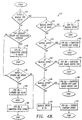
- FIGURES 4C through 4E are flowcharts of an altitude subroutine 200 that estimates an altitude value Alt(a) at which the aircraft should operate during the cruise segment of the diversion. It will be appreciated that in the alternate destination planner described herein it is presumed that the aircraft will fly at a constant altitude from the point at which a diversion is made until the point at which the aircraft begins to descend to the alternate airport.
- the altitude subroutine initially determines whether the aircraft is currently climbing. If the aircraft is climbing, the altitude subroutine proceeds to a decision block 204 where it is determined whether a manual altitude has been entered by the pilot. If the pilot has entered a manual altitude, at a block 206 the altitude subroutine sets the variable Alt(a) equal to the manual altitude entered by the pilot. As discussed above, the altitude entered by the pilot will be displayed using an altitude format or a flight level format. At block 206, the altitude subroutine therefore sets the variable Alt(a) equal to the desired altitude whether expressed in altitude format or flight level format.
- the subroutine proceeds to a decision block 208, where it is determined if the airplane is operating above an optimum altitude. It will be appreciated that the optimum altitude for an aircraft to operate varies with a number of conditions, but is based primarily on the gross weight of the aircraft including fuel. Generally, it is more efficient for a lighter aircraft to operate at a higher altitude than a heavier aircraft. If the airplane is above the optimum altitude, the subroutine proceeds to a block 210 where it sets the variable Alt(a) equal to the cruise altitude.
- the cruise altitude is the altitude cleared by air traffic control for operation of the aircraft, and is typically set by the pilot upon takeoff.
- the altitude subroutine proceeds to a decision block 212 where the subroutine compares the cruise altitude with the optimum altitude. If the cruise altitude is less than the optimum altitude, at a block 214 the variable Alt(a) is set equal to the cruise altitude. If the cruise altitude is greater than the optimum altitude, however, at a block 216 the variable Alt(a) is set equal to the optimum altitude.
- the altitude subroutine proceeds to a decision block 224.
- the subroutine compares the current altitude with the optimum altitude to determine if the current altitude is greater than the optimum altitude. If the current altitude exceeds the optimum altitude, at a block 226 the variable Alt(a) is set equal to the current altitude. If the current altitude is, however, less than the optimum altitude, at a block 228 the subroutine sets the variable Alt(a) equal to the optimum altitude. During a diversion, the aircraft will therefore continue to operate at its current altitude unless the current altitude is less than the optimum altitude, in which case the aircraft is to climb to operate at the optimum altitude.
- the altitude subroutine proceeds to a decision block 230 where it determines whether engine out performance has been selected by the pilot. If engine out performance has not been selected, the subroutine branches to a decision block 232 as shown in FIGURE 4E.
- the branch starting with decision block 232 is therefore representative of the typical operating condition of an aircraft. That is, the airplane is in level flight and both engines are currently operating.
- the altitude subroutine examines the routing option that the aircraft will take in the event of a diversion. If the routing is direct or offset, the altitude subroutine proceeds to a block 234 where the variable Alt(a) is set equal to the cruise altitude. If the routing is overhead, however, the subroutine proceeds to a decision block 236.
- the subroutine determines if the overhead waypoint where diversion from the active flight plan occurs is within the cruise segment of the flight profile. It will be appreciated that the overhead waypoint may come before or after the top of descent point on the flight profile, depending on the proximity of the waypoint to the alternate destination. If the overhead waypoint is after the top of descent point and not in the cruise segment, at a block 238 the variable Alt(a) is set equal to the cruise altitude. If the overhead waypoint is prior to the top of descent point and in the cruise segment, the altitude subroutine proceeds to a decision block 240. At block 240, the altitude subroutine forecasts whether there will be a step climb, or increase in altitude, during the original route segment.
- the aircraft may increase its altitude to operate at a more efficient altitude. Operating at a higher altitude increases the efficiency as the weight of the aircraft decreases due to fuel consumption.
- the altitude subroutine sets the variable Alt(a) equal to the cruise altitude. If there is a step climb forecast during the original route segment, however, at a block 244 the subroutine sets the variable Alt(a) equal to the altitude that the aircraft is expected to step to. The method of forecasting and calculating the magnitude of the step climb is well known in the art, and is not discussed in further detail herein.
- the altitude subroutine compares the cruise altitude with an engine out maximum altitude.
- the engine out maximum altitude is the maximum altitude that the aircraft can operate at with one engine turned off. If the aircraft has been confirmed for a cruise altitude that is less than the engine out maximum altitude, at a block 250 the variable Alt(a) is set equal to the cruise altitude. If, however, the cruise altitude is greater than the engine out maximum altitude, at a block 248 the subroutine sets the variable Alt(a) equal to the engine out maximum altitude.
- An aircraft operating with engine out performance will therefore maintain its cruise altitude unless the cruise altitude is in excess of the engine out maximum altitude. If the cruise altitude is above the engine out maximum altitude, the aircraft will descend to that maximum altitude.
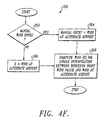
- FIGURE 4F is a flow chart of a wind subroutine 250 that calculates an average wind to be encountered by the aircraft during the cruise segment of the diversion.
- the wind subroutine initially determines whether the pilot has manually entered a value of the wind at the alternate destination. As discussed above, one of the operating conditions that the pilot may specify for each alternate destination is the wind direction and velocity. If the pilot has entered a value for the wind, at a block 254 the value of the wind at the alternate airport is set equal to the entered value. If the pilot has not entered a value for the wind, at a block 256 the wind value at the alternate destination is set equal to zero. At a block 258, the wind subroutine then uses the wind value at the alternate destination and a known wind at the diversion point to determine the average wind over the diversion route.
- the ETA subroutine proceeds to a block 112 where the length in nautical miles of each segment in the diversion plan to the alternate destination are calculated and stored.
- the length of the original route segment is determined from the original flight plan data. As was discussed above with respect to FIGURE 5, the length of the cruise segment is dependent upon the location of the top of descent point.
- the ETA subroutine therefore initially calculates the distance between the diversion point and the alternate destination. In a preferred embodiment, the subroutine then interpolates from an altitude of 1000 feet above the airport back to the estimated altitude of the aircraft during the cruise segment using the predefined descent path. The altitude where the descent path intersects the cruise segment is determined, thereby fixing both the length of the cruise segment and the length of the descent segment. The length of the cruise segment, descent segment, and, if applicable, original route segment are then stored by the ETA subroutine.
- the ETA subroutine continues to a block 114 where the subroutine calculates the ETE during the cruise segment of the diversion, based on the stored values of Spd(a), Alt(a), and Wind(a).
- a flow chart of an ETE subroutine 280 for calculating the estimated time enroute for the cruise segment is shown in FIGURE 4G.
- the ETE subroutine initially determines whether the pilot has made a manual temperature entry in the alternate destination planner. As was discussed above, the pilot may enter the temperature at a certain altitude for each of the alternate destinations. If the pilot has entered a temperature, the ETE subroutine proceeds to a block 284 where the true air speed of the aircraft is computed based on the altitude Alt(a), speed Spd(a), and manually entered outside air temperature. The relationship of these factors to the true air speed of the aircraft is well known in the art, and is not discussed in additional detail herein.
- the ETE subroutine computes the true air speed based on the altitude Alt(a), speed Spd(a), and a standard atmospheric model. After computing the true airspeed of the aircraft, the airspeed is stored at a block 288.
- the ETE subroutine computes the actual ground speed of the aircraft based on the stored value of the true airspeed of the aircraft and the average wind Wind(a).
- the ETE subroutine then computes and stores the ETE of the aircraft along the cruise segment based on the length of the segment and the ground speed.
- the ETA subroutine calculates the ETE for the descent segment at a block 116.
- the estimation technique disclosed herein uses an predefined descent path having a linear slope and predefined speeds. Those skilled in the art will recognize that it is a straightforward matter to calculate the ETE of the descent path knowing the initial altitude of the aircraft, the speed of the aircraft, and the length of the descent segment. In a preferred embodiment of the alternate destination planner, the wind is assumed to be zero and the temperature nominal during the descent segment. After calculating the ETE for the descent segment, the ETE value is stored by the ETA subroutine.
- the ETA subroutine adds the ETEs for each of the segments of the diversion flight plan to arrive at a total time enroute. If overhead routing is selected, the ETEs for the original route segment, cruise segment, and descent segment are added. If direct or offset routing is selected, the ETEs for the cruise segment and descent segment are added.
- the total time enroute is added to the current time maintained in the flight management computer to determine an ETA at the alternate destination. The ETA for the alternate destination is stored and the ETA subroutine returns to the main program.
- ETA subroutine 100 is called eight times to calculate an ETA for each of the eight closest destinations.
- the main program calculates the remaining fuel at each of the eight closest alternate destinations. It will be appreciated that there are several techniques known in the art for calculating an aircraft's fuel consumption given the aircraft's operating altitude and speed, as well as the outside air temperature and wind. Since the length of each segment of the diversion path is known, the amount of fuel remaining at the end of each segment may be readily determined.
- the main program compares the ETA to the eight closest destinations and selects four destinations that have the lowest ETA. The alternate destination planner therefore identifies those alternate destinations that are the closest based on time, rather than distance.
- the main program displays the list of the four closest destinations with the ETA and remaining fuel on the CDU.
- the alternate destinations are ordered according to the ETA, with the closest alternate destination listed first.
- the alternate destination pianner absent any information input by the pilot or flight plan changes the list of alternate destinations and arrival data are updated every five minutes. The period between updates may be extended or reduced, however, depending upon the performance of the aircraft and the importance of maintaining timely information on the display. If the pilot changes the operating conditions or routing options, the displayed data is immediately recalculated.
- the method disclosed herein for estimating the arrival data for each alternate destination provides greater accuracy because it takes into account the aircraft altitude, the aircraft speed, the outside air temperature, the wind, and the selected routing to the alternate destination. Moreover, each of the factors may be modified by the pilot to more accurately reflect the current conditions. The pilot may therefore rely on the arrival data with a higher degree of confidence than prior alternate destination planners.
- the pilot may select the alternate destination to which the aircraft is to divert.
- the closest alternate destination by time is automatically preselected for diversion.
- the preselection is indicated on first screen 50 by a " ⁇ A>" following the four character identifier of the first alternate destination
- the pilot may select the alternate destination by pressing the appropriate key, 1L to 4L, next to the alternate destination.
- FIGURE 6 a series of representative data screens that may be accessed by the pilot on the CDU are provided.
- the manual selection of the third alternate selection on representative screen 300 was performed by pressing key 3L.
- a manual selection of a different alternate destination is indicated by a " ⁇ SEL>" following the identifier of the destination.
- the pilot may immediately divert to the automatically- or manually-selected alternate destination by pressing key 6R.
- key 6R is labeled with the text "DIVERT NOW" under the identifier of the airport that is currently selected for diversion.
- Pushing the divert now key 6R causes the text next to key 6R to change to "SELECTED" as shown in a representative screen 302.
- the word "MOD” appears in the screen title to indicate that a flight plan modification has been selected. Pressing the divert now key causes a route modification to be loaded into the flight management computer.
- the pilot must press the EXEC function key 48.
- pilot may do so by selecting the alternate destination page showing the routing and operating conditions.
- an "ERASE” option is added on the individual alternate destination page next to key 6L. Pressing the erase key clears the flight plan modification and associated information and returns the page to the previous unmodified state.
- the pilot may also modify the diversion to incorporate engine out performance.
- an "ENG OUT" option adjacent key 5L. Pressing the engine out key causes the alternate destination planner to recalculate the arrival data for all of the alternate destinations based on the reduced performance available when the aircraft is only operating un a single engine.
- a new cruise altitude is determined if the current cruise altitude is above the engine out ceiling, and a new engine out speed is loaded for the reduced maximum speed of the aircraft.
- the preferred embodiment of the invention was adapted for use in the two-engine Boeing 777.
- An alternate destination planner incorporated in other aircraft having more than two engines would require a modification to the manner in which the engine out performance was selected.
- a representative screen 306 is provided in FIGURE 6 to further show the effect of implementing a diversion by pressing the EXEC key.
- Screen 306 was accessed on the CDU by depressing the LEGS key 44.
- the active flight plan is discarded and the alternate destination is loaded as the current destination.
- the alternate destination is automatically loaded as the first leg in the new flight plan. Additional data regarding the newly loaded flight plan may be accessed using techniques known to those skilled in using a CDU and flight management computer.
- the alternate destination planner of the present invention also includes the capability of loading alternate destination data that is transmitted via air-ground data link from a ground station to the aircraft during flight.
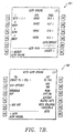
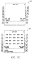
- FIGURE 7 shows a series of representative data screens that may be accessed by the pilot on the CDU in order to request and receive ground station data.
- a pilot presses key 5L, labeled as "ALTN REQUEST.” Pressing the 5L key transmits a request from the aircraft to the ground station for updated information about each of the four alternate destinations displayed on the summary page.
- the ground station may transmit to the aircraft a new list of up to four alternates along with a priority of the alternates. For each alternate, the ground station may transmit a value of the wind, outside air temperature, and overhead diversion waypoint. Additionally, a single diversion speed, altitude, and offset distance for all alternates may be uplinked from the ground station.
- the alternate destination summary page is updated as shown in a representative third screen 324. The numbers above each of the alternate destination identifiers indicate the priority of the alternate destinations as selected by the transmitting ground station.
- the pilot has the option of receiving the entirety of the uplinked data by pressing key 6R, or rejecting the entirety of the uplinked data by pressing key 6L.
- the pilot may view the individual alternate destination data before deciding whether to accept or reject the uplinked data. It will be appreciated that until the pilot accepts or rejects the uplinked data, the pilot may not divert the aircraft to an alternate destination. During the uplink accept/reject period, the DIVERT NOW alternative is removed from both the summary alternate destination page and the individual alternate destination page.
- the pilot also has the capability to request and receive via data link an alternate destination list that is used in place of the navigation database contained in the flight management computer.
- an alternate destination list that is used in place of the navigation database contained in the flight management computer.
- the pilot initially presses either the previous page or next page function keys 40 to arrive at an alternate list page as shown in a representative fifth screen 328.
- a pilot presses key 5L, labeled as "ALTN LIST REQUEST.”
- the alternate list is displayed on the screen as shown in a representative sixth screen 330.
- an airline may uplink a list of up to twenty alternate airports from the ground station.
- the received alternate destination list is automatically used by the alternate destination planner in place of the navigation database. That is, the alternate destination planner selects the four closest alternate destinations for display on the alternate destination summary page exclusively from the uplinked list. If the pilot desires to return to selecting the alternate destinations from the navigation database, the pilot may purge the uplinked list by pressing key 5R, labeled "ALTN LIST PURGE.”
- FIGURE 8 is a pictorial diagram of a representative screen of a navigation display 350 that is coupled to the alternate destination planner through the flight management computer.
- the depicted screen of the navigation display includes an aircraft icon 358 indicating the position and orientation of the aircraft containing the display and a rotating compass scale 352 from which the current heading of the aircraft can be ascertained.
- a distance scale 353 is also provided to allow a pilot to judge the distances to locations represented on the navigation screen. It will be appreciated that other screens may be generated on the typical navigation display other than the own shown in FIGURE 8.
- Line 354 is of a distinguishing color, and indicates a portion of the flight plan of the aircraft through a series of waypoint icons 356.
- the representative flight plan shown in FIGURE 8 passes through a waypoint in SEA (Seattle, Washington) before proceeding through a waypoint in ELN (Ellensburg, Washington). It will be appreciated that due to the scale of the display, only a portion of the active flight plan is displayed. By adjusting the scale of the navigation display, however, a pilot may expand or contract the amount of the flight plan that is represented on the screen.
- the alternate destination planner disclosed herein provides a visual display of the alternate destinations that are within the range of the area represented on the navigation display.
- the alternate destination planner generates a destination icon 360 on the navigation display.
- the destination icon 360 consists of an "A" in a circle and an adjacent listing of the ICAO destination identifier. It will be appreciated that depending upon the scale of the navigation display and the number of alternate destinations in the area surrounding the aircraft, a greater or lesser number of alternate destinations may be displayed on the screen.
- a pilot may toggle a switch to display either the closest alternate destination or all four of the alternate destinations contained in the alternate destination summary list.
- each destination icon 360 on the display is accurately represented with respect to the location of the aircraft icon, allowing a pilot to estimate the heading and distance to the alternate destination.
- the alternate destination KPDX is the closest alternate destination, and that KPDX lies to the right of the current flight plan at a heading of approximately 170 degrees and a distance of approximately 100 nautical miles.
- the navigation display does provide sufficient information to a pilot to make an initial estimation of the flight maneuver required to divert to each destination.
Landscapes
- Engineering & Computer Science (AREA)
- Aviation & Aerospace Engineering (AREA)
- Physics & Mathematics (AREA)
- General Physics & Mathematics (AREA)
- Radar, Positioning & Navigation (AREA)
- Remote Sensing (AREA)
- Automation & Control Theory (AREA)
- Traffic Control Systems (AREA)
- Navigation (AREA)
Claims (18)
- Verfahren des Auswählens eines Ausweichzielorts und des Durchführens einer Umleitung eines Flugzeugs von einem aktiven Flugplan zu einem geplanten Zielort auf einen Umleitungsflugplan zu dem Ausweichzielort, wobei sich die Umleitung an einer Umleitungsstelle ereignet, wobei das Verfahren folgendes umfasst:Durchsuchen (70) einer Datenbank von Zielorten, die in einem Flugleitungs- bzw. -managementcomputer gespeichert sind, um eine Mehrzahl von Ausweichzielorten zu identifizieren, an denen das Flugzeug in der Region, welche das Flugzeug umgibt, landen kann;Bestimmen (82) einer voraussichtlichen Ankunftszeit (ETA) längs eines Umleitungsflugplans zu jedem aus der Mehrzahl der Ausweichzielorte; undAnzeigen bzw. Darstellen (88) der Mehrzahl von alternativen Zielorten bzw. Ausweichzielorten für einen Piloten des Flugzeugs; undDurchführen einer Umleitung zu einem ausgewählten Ausweichzielort mittels Ersetzens des aktiven Flugplans durch einen Umleitungsflugplan; gekennzeichnet durch :Ordnen (86) der Mehrzahl von Ausweichzielorten in der Reihenfolge der Flugzeit zu jedem aus der Mehrzahl der Ausweichzielorte;Auswählen (SEL) von einem aus der Mehrzahl der angezeigten bzw. dargestellten Ausweichzielorte; undBefähigen des Piloten, eine Umleitung zu einem ausgewählten einen aus der Mehrzahl der angezeigten bzw. dargestellten Ausweich-6R-Zielorte in die Wege zu leiten durch Manipulieren einer einzelnen bzw. einzigen Tastatureingabe bzw. eines einzelnen bzw. einzigen Tastatureingangs, die bzw. der mit dem Flugleitungs- bzw. -managementcomputer verbunden ist.
- Verfahren gemäß Anspruch 1, weiter umfassend das Laden der Datenbank von Zielorten in den Flugleitungs- bzw. -managementcomputer von einer Bodenstation her.
- Verfahren gemäß Anspruch 1, worin das Durchsuchen der Datenbank von Zielorten in dem Flugleitungs- bzw. -managementcomputer zum Identifizieren einer Mehrzahl von Ausweichzielorten folgendes umfasst:Bestimmen der Umleitungsstelle des Flugzeugs auf dem aktiven Flugplan;Berechnen einer Entfernung zwischen der Umleitungsstelle des Flugzeugs und jedem der Zielorte in der Datenbank der Zielorte; undAuswählen einer Mehrzahl von Ausweichzielorten aus der Datenbank von Zielorten, welche in der Entfernung am nächsten zu dem Flugzeug sind.
- Verfahren gemäß Anspruch 1, worin die Flugzeit des Flugzeugs längs des Umleitungsflugplans zu jedem aus der Mehrzahl von Ausweichzielorten bestimmt wird durch Teilen des Umleitungsflugplans in eine Mehrzahl von Abschnitte, Berechnen einer Flugzeit für jeden aus der Mehrzahl der Abschnitte und Summieren der Flugzeiten für jeden aus der Mehrzahl der Abschnitte.
- Verfahren gemäß Anspruch 4, worin die Flugzeit für jeden aus der Mehrzahl der Abschnitte berechnet wird durch:Bestimmen (150) einer gewünschten Geschwindigkeit des Flugzeugs, wobei die gewünschte Geschwindigkeit durch den Piloten eingebbar ist oder ein vorbestimmter Wert ist, wenn sie nicht durch den Piloten eingegeben wird;Bestimmen (200) einer gewünschten Höhe des Flugzeugs, wobei die gewünschte Höhe durch den Piloten eingebbar ist oder ein vorbestimmter Wert ist, wenn sie nicht durch den Piloten eingegeben wird;Bestimmen (282) einer Außenlufttemperatur, wobei die Außenlufttemperatur durch den Piloten eingebbar ist oder ein vorbestimmter Wert ist, wenn sie nicht durch den Piloten eingegeben wird;Berechnen (284, 286) einer Flug- bzw. Eigengeschwindigkeit des Flugzeugs unter Verwendung der Ergebnisse der obigen Rechnerschritte;Berechnen (292) einer Entfernung zwischen der Umleitungsstelle des Flugzeugs und dem Ausweichzielort längs des Umleitungsflugplans; undBerechnen einer Flugzeit für den Abschnitt mittels Teilens der Entfernung durch die Flug- bzw. Eigengeschwindigkeit des Flugzeugs.
- Verfahren gemäß Anspruch 5, worin der mittlere Wind, der durch das Flugzeug zwischen Umleitungsstellen des Flugzeugs und dem Ausweichzielort erfahren wird, eine lineare Interpolation des Winds an der Umleitungsstelle des Flugzeugs und des Winds an dem Ausweichzielort ist, wobei der Wind an dem Ausweichzielort durch den Piloten eingebbar ist.
- Verfahren gemäß Anspruch 1, worin das Anzeigen bzw. Darstellen der Mehrzahl von Ausweichzielorten für den Piloten das Anzeigen bzw. Darstellen (50) einer geordneten Liste von der Mehrzahl der Ausweichzielorte von der geringsten Flugzeit bis zur größten Flugzeit umfasst.
- Verfahren gemäß Anspruch 1, worin das Anzeigen bzw. Darstellen der Mehrzahl von Ausweichzielorten für den Piloten folgendes umfasst:Anzeigen bzw. Darstellen eines Flugzeugpiktogramms (358), das für eine Position und eine Ausrichtung des Flugzeugs auf einem Navigationsdisplay bezeichnend ist; undAnzeigen bzw. Darstellen eines Orts aus der Mehrzahl der Ausweichzielorte auf dem Navigationsdisplay, wobei jeder aus der Mehrzahl der Ausweichzielorte in einer relativen Ausrichtung und in einer relativen Entfernung mit Bezug auf die Position und die Ausrichtung des Flugzeugpiktogramms angezeigt bzw. dargestellt wird.
- Verfahren gemäß Anspruch 8, weiter umfassend das Anzeigen bzw. Darstellen des aktiven Flugplans des Flugzeugs auf dem Navigationsdisplay.
- Verfahren gemäß Anspruch 9, weiter umfassend das Anzeigen bzw. Darstellen des Umleitungsflugplans des Flugzeugs auf dem Navigationsdisplay nach dem Durchführen einer Umleitung zu dem ausgewählten Ausweichzielort.
- Verfahren gemäß Anspruch 1, weiter umfassend das Befähigen des Piloten, einen Typ von Umleitungsflugplan vor dem Einleiten der Umleitung auszuwählen.
- Verfahren gemäß Anspruch 11, worin der Typ des Umleitungsflugplans aus einer Gruppe von Flugplänen ausgewählt wird, bestehend aus Direkt-, Ersatz- und Zusatzumleitungsflugplänen.
- Verfahren gemäß Anspruch 1, worin der aus der Mehrzahl von angezeigten bzw. dargestellten Ausweichzielorten ausgewählte Ausweichzielort durch den Flugleitungs- bzw. -managementcomputer ausgewählt wird.
- Verfahren gemäß Anspruch 13, worin der aus der Mehrzahl von angezeigten bzw. dargestellten Ausweichzielorten ausgewählte Answeichzielort der Ausweichzielort ist, der eine kürzeste Flugzeit hat.
- Verfahren gemäß Anspruch 1, worin der aus der Mehrzahl der angezeigten bzw. dargestellten Ausweich- bzw. Altemativzielorten ausgewählte Ausweich- bzw. Alternativzielort durch den Piloten ausgewählt wird.
- Flugleitungs- bzw. -managementcomputer (FMC), umfassend:ein Speichermittel zum Speichern einer Datenbank von einer Mehrzahl von Zielorten;ein Durchsuchungsmittel (70) zum Suchen einer Mehrzahl von Ausweichzielorten in der Datenbank von Zielorten, an denen das Flugzeug in der Region, die das Flugzeug umgibt, landen kann;ein Bestimmungsmittel (82) zum Bestimmen einer voraussichtlichen Ankunftszeit (ETA) längs eines Flugplans zu jedem aus der Mehrzahl von Zielorten;ein Displaymittel (30) zum Anzeigen bzw. Darstellen der Mehrzahl von Zielorten für einen Piloten des Flugzeugs;ein Durchführungsmittel zum Durchführen einer Umleitung zu einem ausgewählten Ausweichzielort mittels Ersetzen des aktiven Flugplans durch einen Umleitungsflugplan; gekennzeichnet durchein Ordnungsmittel (86) zum Ordnen der Mehrzahl von Ausweichzielorten in der Reihenfolge der Flugzeit zu jedem aus der Mehrzahl der Ausweichzielorte; undeinen einzelnen bzw. einzigen Tastatureingang zum Befähigen des Piloten, eine Umleitung zu einem ausgewählten einen aus der Mehrzahl der angezeigten bzw. dargestellten Ausweichzielorte einzuleiten durch Manipulieren eines einzelnen bzw. einzigen Tastatureingangs, der mit dem Flugleitungs- bzw. -managementcomputer verbunden ist.
- Verfahren zum Identifizieren einer Mehrzahl von Ausweichzielorten für das Landen des Flugzeugs aus der Datenbank der Zielorte und Anzeigen bzw. Darstellen einer Mehrzahl von Ausweichzielorten für einen Piloten des Flugzeugs für das Landen des Flugzeugs, wenn das Flugzeug nicht an seinem geplanten Zielort gelandet werden kann, wobei das Verfahren folgendes umfasst:Bestimmen einer Entfernung zwischen einer gegenwärtigen Position des Flugzeugs und einem Ort von jedem Zielort innerhalb der Datenbank von Zielorten, die in dem Flugleitungs- bzw. -managementcomputer gespeichert ist;Identifizieren (80) von einer Mehrzahl von Ausweichzielorten aus der Datenbank von Zielorten, die in der Entfernung zu dem Flugzeug am nächstliegensten sind;Bestimmen (82) einer Flugzeit längs eines Umleitungsflugplans zu jedem aus der Mehrzahl der Ausweichzielorte; undAnzeigen bzw. Darstellen (88) der Mehrzahl von Ausweichzielorten für den Piloten, gekennzeichnet durch die Schritte des:Ordnens der Mehrzahl von Ausweichzielorten in der Reihenfolge der Flugzeit zu jedem aus der Mehrzahl der Ausweichzielorte;automatischen Aktualisierens der Mehrzahl von Ausweichzielorten, wenn der Pilot die Betriebsbedingungen oder die Leitwegoptionen ändert; undautomatischen Aktualisierens der Mehrzahl von Ausweichzielorten beim Ablauf einer vorbestimmten Zeitdauer.
- Verfahren gemäß irgendeinem der Ansprüche 1-15, umfassend die Verfahrensschritte des Anspruchs 17.
Applications Claiming Priority (2)
| Application Number | Priority Date | Filing Date | Title |
|---|---|---|---|
| US440731 | 1995-05-15 | ||
| US08/440,731 US5842142A (en) | 1995-05-15 | 1995-05-15 | Least time alternate destination planner |
Publications (2)
| Publication Number | Publication Date |
|---|---|
| EP0743580A1 EP0743580A1 (de) | 1996-11-20 |
| EP0743580B1 true EP0743580B1 (de) | 2003-05-28 |
Family
ID=23749948
Family Applications (1)
| Application Number | Title | Priority Date | Filing Date |
|---|---|---|---|
| EP95203125A Revoked EP0743580B1 (de) | 1995-05-15 | 1996-03-19 | Kürzestzeit Alternativzielplaner |
Country Status (3)
| Country | Link |
|---|---|
| US (1) | US5842142A (de) |
| EP (1) | EP0743580B1 (de) |
| DE (1) | DE69628375T2 (de) |
Cited By (1)
| Publication number | Priority date | Publication date | Assignee | Title |
|---|---|---|---|---|
| AU2019206386B2 (en) * | 2018-01-10 | 2024-09-19 | Qualcomm Incorporated | Identifying landing zones for landing of a robotic vehicle |
Families Citing this family (129)
| Publication number | Priority date | Publication date | Assignee | Title |
|---|---|---|---|---|
| JP3406478B2 (ja) * | 1997-06-06 | 2003-05-12 | 沖電気工業株式会社 | ターミナル管制用管制卓の航空機位置表示装置 |
| FR2783500B1 (fr) * | 1998-09-23 | 2000-12-08 | Eurocopter France | Dispositif d'aide au pilotage d'un aeronef, notamment a voilure tournante et en particulier un helicoptere |
| JP4251466B2 (ja) | 1998-12-04 | 2009-04-08 | 富士通株式会社 | 自動化レベル調整装置,自動化レベル調整方法および自動化レベル調整用プログラム記録媒体 |
| US6314361B1 (en) * | 1999-07-30 | 2001-11-06 | Caleb Technologies Corp. | Optimization engine for flight assignment, scheduling and routing of aircraft in response to irregular operations |
| DE10019407A1 (de) * | 2000-04-19 | 2001-10-25 | Bosch Gmbh Robert | Verfahren zur Routenberechnung und Verfahren zur Zielführung |
| ATE389193T1 (de) * | 2000-04-25 | 2008-03-15 | Honeywell Int Inc | Flugzeugfunkfrequenznominierung |
| US6915204B1 (en) | 2000-06-01 | 2005-07-05 | Webraska, Inc. | Method, system, and article of manufacture for minimizing travel time to a user selected location |
| US6353797B1 (en) | 2000-06-01 | 2002-03-05 | Airflash | Database minimizing by wireless input of location related information |
| US6522958B1 (en) | 2000-10-06 | 2003-02-18 | Honeywell International Inc. | Logic method and apparatus for textually displaying an original flight plan and a modified flight plan simultaneously |
| US6922631B1 (en) * | 2000-10-06 | 2005-07-26 | Honeywell International Inc. | System and method for textually displaying an original flight plan and a modified flight plan simultaneously |
| US7724240B2 (en) * | 2000-10-06 | 2010-05-25 | Honeywell International Inc. | Multifunction keyboard for advanced cursor driven avionic flight decks |
| US6856864B1 (en) * | 2000-11-17 | 2005-02-15 | Honeywell International Inc. | Method and system for entering data within a flight plan entry field |
| DE60127808T2 (de) * | 2001-03-19 | 2007-12-27 | Kabushiki Kaisha Toshiba | Navigationshilfesystem, Flugroutenberechnungsverfahren und Navigationshilfeverfahren |
| US6600994B1 (en) | 2001-05-17 | 2003-07-29 | Horizon Navigation, Inc. | Quick selection of destinations in an automobile navigation system |
| US6804585B2 (en) * | 2001-06-19 | 2004-10-12 | John Jay Humbard | Flight management system and method for providing navigational reference to emergency landing locations |
| US6812858B2 (en) | 2001-08-20 | 2004-11-02 | The Boeing Company | Integrated display for aircrafts |
| US7568662B1 (en) | 2001-09-12 | 2009-08-04 | Honeywell International Inc. | Emergency flight control system |
| US6606553B2 (en) | 2001-10-19 | 2003-08-12 | The Mitre Corporation | Traffic flow management method and system for weather problem resolution |
| AU2002324984A1 (en) * | 2001-11-27 | 2003-06-10 | Honeywell International Inc. | Emergency flight control system |
| US7221287B2 (en) * | 2002-03-05 | 2007-05-22 | Triangle Software Llc | Three-dimensional traffic report |
| ITRM20020371A1 (it) * | 2002-07-10 | 2004-01-12 | Maurizio Catello Pennarola | Sistema di gestione della navigazione di velivoli fuori rotta e comunicazioni di allarme. |
| SE0300871D0 (sv) * | 2003-03-27 | 2003-03-27 | Saab Ab | Waypoint navigation |
| FR2854948B1 (fr) * | 2003-05-16 | 2005-07-29 | Thales Sa | Systeme de gestion de vol |
| FR2857480B1 (fr) * | 2003-07-07 | 2005-09-30 | Airbus France | Procede et dispositif de generation d'un plan de vol pour un vol tactique d'un aeronef |
| WO2005013063A2 (en) | 2003-07-25 | 2005-02-10 | Landsonar, Inc. | System and method for determining recommended departure time |
| US20050049762A1 (en) * | 2003-08-26 | 2005-03-03 | Dwyer David B. | Integrated flight management and textual air traffic control display system and method |
| US7702427B1 (en) * | 2004-07-30 | 2010-04-20 | The United States Of America As Represented By The National Aeronautics And Space Administration (Nasa) | Air traffic management evaluation tool |
| US7512462B2 (en) * | 2004-11-16 | 2009-03-31 | Northrop Grumman Corporation | Automatic contingency generator |
| US8606516B2 (en) | 2004-11-30 | 2013-12-10 | Dash Navigation, Inc. | User interface system and method for a vehicle navigation device |
| ATE534016T1 (de) * | 2005-09-30 | 2011-12-15 | Saab Ab | Verfahren zum planen der geschwindigkeit eines fahrzeugs entlang einer route |
| US7874521B2 (en) * | 2005-10-17 | 2011-01-25 | Hoshiko Llc | Method and system for aviation navigation |
| FR2893443B1 (fr) * | 2005-11-16 | 2011-07-08 | Thales Sa | Systeme et procede de changement de trajectoire d'apparoche du plan de vol d'un aeronef en phase d'approche d'une piste d'atterrissage comportant un point d'alignement |
| US11390165B2 (en) | 2005-11-17 | 2022-07-19 | Invently Automotive Inc. | Electric vehicle power management system |
| US11279233B2 (en) | 2005-11-17 | 2022-03-22 | Invently Automotive Inc. | Electric vehicle power management system |
| US11214144B2 (en) | 2005-11-17 | 2022-01-04 | Invently Automotive Inc. | Electric vehicle power management system |
| US11254211B2 (en) | 2005-11-17 | 2022-02-22 | Invently Automotive Inc. | Electric vehicle power management system |
| US11370302B2 (en) | 2005-11-17 | 2022-06-28 | Invently Automotive Inc. | Electric vehicle power management system |
| US11325468B2 (en) | 2005-11-17 | 2022-05-10 | Invently Automotive Inc. | Vehicle power management system |
| US11084377B2 (en) | 2005-11-17 | 2021-08-10 | Invently Automotive Inc. | Vehicle power management system responsive to voice commands from a Gps enabled device |
| US11267338B2 (en) | 2005-11-17 | 2022-03-08 | Invently Automotive Inc. | Electric vehicle power management system |
| US11207981B2 (en) | 2005-11-17 | 2021-12-28 | Invently Automotive Inc. | Vehicle power management system |
| US11285810B2 (en) | 2005-11-17 | 2022-03-29 | Invently Automotive Inc. | Vehicle power management system |
| US11230190B2 (en) | 2005-11-17 | 2022-01-25 | Invently Automotive Inc. | Electric vehicle power management system |
| US11180025B2 (en) | 2005-11-17 | 2021-11-23 | Invently Automotive Inc. | Electric vehicle power management system |
| US11220179B2 (en) | 2005-11-17 | 2022-01-11 | Invently Automotive Inc. | Vehicle power management system determining route segment length |
| US11186173B2 (en) | 2005-11-17 | 2021-11-30 | Invently Automotive Inc. | Electric vehicle power management system |
| US11247564B2 (en) | 2005-11-17 | 2022-02-15 | Invently Automotive Inc. | Electric vehicle power management system |
| US11279234B2 (en) | 2005-11-17 | 2022-03-22 | Invently Automotive Inc. | Vehicle power management system |
| US11267339B2 (en) | 2005-11-17 | 2022-03-08 | Invently Automotive Inc. | Vehicle power management system |
| US11186175B2 (en) | 2005-11-17 | 2021-11-30 | Invently Automotive Inc. | Vehicle power management system |
| US11186174B2 (en) | 2005-11-17 | 2021-11-30 | Invently Automotive Inc. | Vehicle power management system |
| US11351863B2 (en) | 2005-11-17 | 2022-06-07 | Invently Automotive Inc. | Vehicle power management system |
| US11225144B2 (en) | 2005-11-17 | 2022-01-18 | Invently Automotive Inc. | Vehicle power management system |
| US10882399B2 (en) | 2005-11-17 | 2021-01-05 | Invently Automotive Inc. | Electric vehicle power management system |
| US11207980B2 (en) | 2005-11-17 | 2021-12-28 | Invently Automotive Inc. | Vehicle power management system responsive to traffic conditions |
| US8712650B2 (en) | 2005-11-17 | 2014-04-29 | Invent.Ly, Llc | Power management systems and designs |
| US11345236B2 (en) | 2005-11-17 | 2022-05-31 | Invently Automotive Inc. | Electric vehicle power management system |
| FR2894368B1 (fr) * | 2005-12-07 | 2008-01-25 | Thales Sa | Dispositif et procede de construction automatisee de trajectoire d'urgence pour aeronefs |
| US7668647B2 (en) * | 2006-04-14 | 2010-02-23 | Avidyne Corporation | Computer method and apparatus for filling in an entry field using geographical proximity and character criteria |
| FR2905505B1 (fr) * | 2006-08-30 | 2014-08-15 | Thales Sa | Methode de guidage pour deviation temporaire d'un vehicule suivant initialement une trajectoire predefinie. |
| FR2906048B1 (fr) * | 2006-09-19 | 2008-12-19 | Thales Sa | Procede et dispositif de modification d'un plan de vol et notamment d'une procedure de decollage pour un aeronef |
| FR2910616B1 (fr) * | 2006-12-22 | 2009-09-11 | Thales Sa | Dispositif et procede d'assistance au choix d'aeroports de deroutement |
| US7979199B2 (en) * | 2007-01-10 | 2011-07-12 | Honeywell International Inc. | Method and system to automatically generate a clearance request to deviate from a flight plan |
| FR2912242B1 (fr) | 2007-02-07 | 2009-03-13 | Airbus France Sas | Dispositif et procede d'aide a la gestion d'une panne moteur d'un aeronef |
| FR2912243B1 (fr) * | 2007-02-07 | 2009-03-13 | Airbus France Sas | Dispositif et procede d'aide a la gestion d'une panne moteur d'un aeronef |
| FR2916840B1 (fr) * | 2007-05-29 | 2009-09-11 | Thales Sa | Procede et dispositif de calcul d'un plan de vol |
| US7698026B2 (en) * | 2007-06-14 | 2010-04-13 | The Boeing Company | Automatic strategic offset function |
| US8428794B2 (en) * | 2007-07-26 | 2013-04-23 | The Boeing Company | Method and apparatus for managing instrument missed approaches |
| ES2385403T3 (es) * | 2007-09-21 | 2012-07-24 | The Boeing Company | Predicción de la trayectoria de una aeronave |
| US20090125222A1 (en) * | 2007-11-13 | 2009-05-14 | Honeywell International, Inc. | Flight plan comparison system and method |
| FR2924833B1 (fr) * | 2007-12-07 | 2014-02-07 | Thales Sa | Selection manuelle de la reference active d'un plan de vol pour le guidage d'un aeronef |
| US9257047B2 (en) * | 2007-12-12 | 2016-02-09 | The Boeing Company | Computation of new aircraft trajectory using time factor |
| US8700249B1 (en) * | 2008-07-25 | 2014-04-15 | Jeffrey A. Carrithers | Method and system for fuel route planning |
| US8285427B2 (en) * | 2008-07-31 | 2012-10-09 | Honeywell International Inc. | Flight deck communication and display system |
| US8010267B2 (en) * | 2008-10-31 | 2011-08-30 | General Electric Company | Methods and system for time of arrival control using available speed authority |
| FR2940426B1 (fr) * | 2008-12-23 | 2010-12-10 | Thales Sa | Dispositif d'assistance au choix d'un aeroport de deroutement |
| US20100161153A1 (en) * | 2008-12-23 | 2010-06-24 | Arinc Incorporated | Method and apparatus for automatically determining stopover airports for flight planning |
| CN102265115A (zh) * | 2008-12-25 | 2011-11-30 | 三洋电机株式会社 | 车载用电子设备 |
| US8619072B2 (en) | 2009-03-04 | 2013-12-31 | Triangle Software Llc | Controlling a three-dimensional virtual broadcast presentation |
| US8321069B2 (en) * | 2009-03-26 | 2012-11-27 | Honeywell International Inc. | Methods and systems for reviewing datalink clearances |
| JP5487677B2 (ja) * | 2009-03-30 | 2014-05-07 | 富士通株式会社 | 位置情報サービス装置、方法、及びプログラム |
| US8193947B2 (en) * | 2009-08-04 | 2012-06-05 | Honeywell International Inc. | Methods and systems for generating data link air traffic control center menus |
| US8565944B1 (en) * | 2009-10-13 | 2013-10-22 | The Boeing Company | Alternate diversion airport planner |
| FR2956763B1 (fr) * | 2010-02-24 | 2016-01-29 | Airbus Operations Sas | Systeme embarque a bord d'un aeronef en lien avec un plan de vol |
| US8453160B2 (en) | 2010-03-11 | 2013-05-28 | Honeywell International Inc. | Methods and systems for authorizing an effector command in an integrated modular environment |
| US9520066B2 (en) * | 2010-04-21 | 2016-12-13 | The Boeing Company | Determining landing sites for aircraft |
| US9257048B1 (en) | 2010-04-21 | 2016-02-09 | The Boeing Company | Aircraft emergency landing route system |
| US9127944B2 (en) | 2010-08-06 | 2015-09-08 | Honeywell International Inc. | Avionics display interface and method of operation |
| US8583352B2 (en) | 2010-11-22 | 2013-11-12 | Ge Aviation Systems, Llc | Method and system for hold path computation to meet required hold departure time |
| WO2012159083A2 (en) | 2011-05-18 | 2012-11-22 | Triangle Software Llc | System for providing traffic data and driving efficiency data |
| US8977482B2 (en) | 2011-09-28 | 2015-03-10 | The United States Of America As Represented By The Administrator Of The National Aeronautics And Space Administration | Method and apparatus for generating flight-optimizing trajectories |
| FR2983176B1 (fr) | 2011-11-29 | 2013-12-27 | Airbus Operations Sas | Dispositif de dialogue interactif entre un operateur d'un aeronef et un systeme de guidage dudit aeronef. |
| US8666649B2 (en) * | 2012-01-05 | 2014-03-04 | The Boeing Company | Systems and methods for use in identifying at least one alternate airport |
| JP6260101B2 (ja) | 2012-05-01 | 2018-01-17 | 株式会社リコー | 通信端末、起動方法及びプログラム |
| US10223909B2 (en) | 2012-10-18 | 2019-03-05 | Uber Technologies, Inc. | Estimating time travel distributions on signalized arterials |
| FR3001066B1 (fr) | 2013-01-11 | 2015-02-27 | Airbus Operations Sas | Systeme d'assistance au guidage d'actions a realiser par un operateur sur un aeronef. |
| US9280904B2 (en) | 2013-03-15 | 2016-03-08 | Airbus Operations (S.A.S.) | Methods, systems and computer readable media for arming aircraft runway approach guidance modes |
| US9567099B2 (en) * | 2013-04-11 | 2017-02-14 | Airbus Operations (S.A.S.) | Aircraft flight management devices, systems, computer readable media and related methods |
| CA2915988C (en) | 2013-06-25 | 2019-03-05 | Mark D. Yerger | Transport communication management |
| US8977484B1 (en) | 2013-08-22 | 2015-03-10 | The Boeing Company | Using aircraft trajectory data to infer aircraft intent |
| US9248915B2 (en) | 2013-08-30 | 2016-02-02 | Insitu, Inc. | Systems and methods for fuel monitoring |
| US10885010B2 (en) | 2013-12-18 | 2021-01-05 | Federal Express Corporation | Methods and systems for data structure optimization |
| US10026324B2 (en) | 2014-11-04 | 2018-07-17 | Honeywell International Inc. | Systems and methods for enhanced adoptive validation of ATC clearance requests |
| FR3035534B1 (fr) * | 2015-04-21 | 2019-06-07 | Thales | Procede et systeme de communication et de partage d'informations pour aeronef |
| US10801841B1 (en) * | 2015-10-29 | 2020-10-13 | National Technology & Engineering Solutions Of Sandia, Llc | Trajectory prediction via a feature vector approach |
| US10096253B2 (en) * | 2015-11-30 | 2018-10-09 | Honeywell International Inc. | Methods and systems for presenting diversion destinations |
| US10304344B2 (en) | 2016-02-09 | 2019-05-28 | Honeywell International Inc. | Methods and systems for safe landing at a diversion airport |
| US9640079B1 (en) | 2016-02-09 | 2017-05-02 | Honeywell International Inc. | Methods and systems facilitating holding for an unavailable destination |
| US10134289B2 (en) | 2016-02-18 | 2018-11-20 | Honeywell International Inc. | Methods and systems facilitating stabilized descent to a diversion airport |
| FR3050291B1 (fr) * | 2016-04-15 | 2020-02-28 | Thales | Procede d'affichage de donnees pour la gestion du vol d'un aeronef, produit programme d'ordinateur et systeme associes |
| US9884690B2 (en) * | 2016-05-03 | 2018-02-06 | Honeywell International Inc. | Methods and systems for conveying destination viability |
| US10109203B2 (en) | 2016-09-07 | 2018-10-23 | Honeywell International Inc. | Methods and systems for presenting en route diversion destinations |
| US10540899B2 (en) | 2016-11-21 | 2020-01-21 | Honeywell International Inc. | Flight plan segmentation for en route diversion destinations |
| US10896618B2 (en) | 2017-05-03 | 2021-01-19 | Honeywell International Inc. | System and method for determining diversion airports for landing in adverse conditions |
| US10641615B2 (en) * | 2017-08-11 | 2020-05-05 | Honeywell International Inc. | Methods and apparatus for displaying flight interval management data for selecting appropriate flight management settings |
| US10607496B2 (en) | 2018-04-10 | 2020-03-31 | Honeywell International Inc. | System and method to assist pilots in determining aircraft phase transition time based on monitored clearance information |
| US11393343B2 (en) | 2019-02-27 | 2022-07-19 | Honeywell International Inc. | System and method for enabling automatic diversion management |
| US20210082290A1 (en) * | 2019-09-13 | 2021-03-18 | The Boeing Company | Determining an airport for landing an aircraft |
| CN110940338A (zh) * | 2019-10-23 | 2020-03-31 | 浩亚信息科技有限公司 | 航空医疗最佳路径选取方法及存储介质 |
| EP3813038A1 (de) * | 2019-10-24 | 2021-04-28 | Airbus Operations SAS | Verfahren und system zur unterstützung der landung eines flugzeugs |
| FR3103588B1 (fr) * | 2019-11-26 | 2021-11-05 | Thales Sa | Procede et dispositif electronique de gestion d'une fonction de recherche d'element(s) geolocalise(s) avec ordonnancement des elements suivant leur distance par rapport a une reference, programme d'ordinateur et systeme ihm |
| US11551562B2 (en) | 2020-05-14 | 2023-01-10 | The Boeing Company | Efficient flight planning for regions with high elevation terrain |
| US12165529B2 (en) | 2020-07-31 | 2024-12-10 | Aurora Flight Sciences Corporation | Selection of an alternate destination in response to a contingency event |
| US11574549B2 (en) * | 2020-10-19 | 2023-02-07 | Honeywell International Inc. | Composite vertical profile display systems and methods |
| EP4268214A4 (de) * | 2020-12-22 | 2024-11-20 | Skyryse, Inc. | Auswahl eines ungeplanten landeplatzes für flugzeuge |
| CN113222282B (zh) * | 2021-05-31 | 2024-06-18 | 北京京东乾石科技有限公司 | 运送路径确定方法和装置、可读存储介质、电子设备 |
| US12249242B2 (en) * | 2022-07-12 | 2025-03-11 | The Boeing Company | Holding detection and diversion information |
| US12559252B2 (en) | 2023-07-12 | 2026-02-24 | The Boeing Company | Systems and methods for real time determination of a fuel level for an aircraft |
| US20260105848A1 (en) * | 2024-10-10 | 2026-04-16 | Honeywell International Inc. | Systems, apparatuses, methods, and computer program products for determining aviation mission impacts |
Family Cites Families (9)
| Publication number | Priority date | Publication date | Assignee | Title |
|---|---|---|---|---|
| US4086632A (en) * | 1976-09-27 | 1978-04-25 | The Boeing Company | Area navigation system including a map display unit for establishing and modifying navigation routes |
| US4692869A (en) * | 1985-03-28 | 1987-09-08 | The Boeing Company | Aircraft navigational systems and methods for creating navigational guidepoints |
| US4774670A (en) * | 1985-04-29 | 1988-09-27 | Lockheed Corporation | Flight management system |
| EP0236587A3 (de) * | 1986-02-06 | 1989-03-22 | The Boeing Company | Zeitabhängiges System zur Flugoptimierung |
| US5041982A (en) * | 1988-12-12 | 1991-08-20 | Honeywell Inc. | Edit area algorithm for navigation display of an electronic flight instrument system |
| US5121325A (en) * | 1990-04-04 | 1992-06-09 | Smiths Industries Aerospace & Defense Systems, Inc. | Required time of arrival (RTA) control system |
| US5398186A (en) * | 1991-12-17 | 1995-03-14 | The Boeing Company | Alternate destination predictor for aircraft |
| US5408413A (en) * | 1993-08-03 | 1995-04-18 | Honeywell Inc. | Apparatus and method for controlling an optimizing aircraft performance calculator to achieve time-constrained navigation |
| US5574647A (en) * | 1993-10-04 | 1996-11-12 | Honeywell Inc. | Apparatus and method for computing wind-sensitive optimum altitude steps in a flight management system |
-
1995
- 1995-05-15 US US08/440,731 patent/US5842142A/en not_active Expired - Lifetime
-
1996
- 1996-03-19 EP EP95203125A patent/EP0743580B1/de not_active Revoked
- 1996-03-19 DE DE69628375T patent/DE69628375T2/de not_active Expired - Lifetime
Cited By (2)
| Publication number | Priority date | Publication date | Assignee | Title |
|---|---|---|---|---|
| AU2019206386B2 (en) * | 2018-01-10 | 2024-09-19 | Qualcomm Incorporated | Identifying landing zones for landing of a robotic vehicle |
| EP3738114B1 (de) * | 2018-01-10 | 2024-11-20 | Qualcomm Incorporated | Identifizierung von landezonen für die landung eines roboterfahrzeugs |
Also Published As
| Publication number | Publication date |
|---|---|
| DE69628375D1 (de) | 2003-07-03 |
| EP0743580A1 (de) | 1996-11-20 |
| US5842142A (en) | 1998-11-24 |
| DE69628375T2 (de) | 2003-11-27 |
Similar Documents
| Publication | Publication Date | Title |
|---|---|---|
| EP0743580B1 (de) | Kürzestzeit Alternativzielplaner | |
| US5526265A (en) | Alternate destination predictor for aircraft | |
| EP2362289B1 (de) | Verfahren und Systeme zur Anzeige vorhersagbarer Parameter stromabwärts in einer vertikalen Profilanzeige | |
| EP0257702B1 (de) | Navigationsvorrichtung und Verfahren zur Anzeige der Flugkörperposition bezüglich eines gewählten vertikalen Flugwegprofils | |
| EP2561501B1 (de) | Bestimmung von landeplätzen für flugzeuge | |
| US6038498A (en) | Apparatus and mehod for aircraft monitoring and control including electronic check-list management | |
| US7433779B2 (en) | Method of following the course of the flight plan of a cooperative aircraft | |
| US7904213B2 (en) | Method of assisting in the navigation of an aircraft with an updating of the flight plan | |
| US6163743A (en) | Process and device for aiding aerial navigation | |
| US8467966B2 (en) | Device for aiding the flight management of an aircraft | |
| EP2685292A2 (de) | Systeme und Verfahren für Flugmanagement | |
| EP2793206B1 (de) | Verfahren und Systeme zur Anzeige von Verfahrensinformation auf einem Flugzeugbildschirm | |
| CN106385442B (zh) | 将新导航服务整合到开放式构架的航空电子机载系统中的方法 | |
| US11430343B2 (en) | Aircraft mission computing system comprising a mission deck | |
| US9494945B2 (en) | Flight management device for an aircraft adapted to the handling of multiple time constraints and corresponding method | |
| EP3407332B1 (de) | System und verfahren zur bestimmung der unsicherheit in einer prognostizierten flugbahn für ein luftfahrzeug | |
| US4538229A (en) | System for preparing aircraft driftdown plans | |
| EP2690409B1 (de) | Verfahren zur Anzeige der Eignung von zukünftigen Wegpunktstellen | |
| US20220122466A1 (en) | Composite vertical profile display systems and methods | |
| EP3936376B1 (de) | System und verfahren für eine einsatzbasierte batteriezustandsanzeige für elektrofahrzeuge | |
| EP1873606B1 (de) | Abbruchgeschützte Routenplanung | |
| US12576987B2 (en) | Computer-based systems and methods for facilitating aircraft approach | |
| EP3985646A1 (de) | Systeme und verfahren zur anzeige von zusammengesetzten vertikalen profilen | |
| US11587447B2 (en) | Dynamically modifiable parameters in required time of arrival (RTA) regions of an assigned flight path | |
| WO2025085627A1 (en) | Computer-based systems and methods for facilitating aircraft approach |
Legal Events
| Date | Code | Title | Description |
|---|---|---|---|
| PUAI | Public reference made under article 153(3) epc to a published international application that has entered the european phase |
Free format text: ORIGINAL CODE: 0009012 |
|
| AK | Designated contracting states |
Kind code of ref document: A1 Designated state(s): DE FR GB |
|
| 17P | Request for examination filed |
Effective date: 19961202 |
|
| 17Q | First examination report despatched |
Effective date: 19971111 |
|
| GRAG | Despatch of communication of intention to grant |
Free format text: ORIGINAL CODE: EPIDOS AGRA |
|
| GRAG | Despatch of communication of intention to grant |
Free format text: ORIGINAL CODE: EPIDOS AGRA |
|
| GRAG | Despatch of communication of intention to grant |
Free format text: ORIGINAL CODE: EPIDOS AGRA |
|
| GRAH | Despatch of communication of intention to grant a patent |
Free format text: ORIGINAL CODE: EPIDOS IGRA |
|
| GRAH | Despatch of communication of intention to grant a patent |
Free format text: ORIGINAL CODE: EPIDOS IGRA |
|
| GRAA | (expected) grant |
Free format text: ORIGINAL CODE: 0009210 |
|
| AK | Designated contracting states |
Designated state(s): DE FR GB |
|
| REG | Reference to a national code |
Ref country code: GB Ref legal event code: FG4D |
|
| REF | Corresponds to: |
Ref document number: 69628375 Country of ref document: DE Date of ref document: 20030703 Kind code of ref document: P |
|
| PLBI | Opposition filed |
Free format text: ORIGINAL CODE: 0009260 |
|
| PLBQ | Unpublished change to opponent data |
Free format text: ORIGINAL CODE: EPIDOS OPPO |
|
| ET | Fr: translation filed | ||
| PLAX | Notice of opposition and request to file observation + time limit sent |
Free format text: ORIGINAL CODE: EPIDOSNOBS2 |
|
| 26 | Opposition filed |
Opponent name: AIRBUS SAS Effective date: 20040226 |
|
| PLAX | Notice of opposition and request to file observation + time limit sent |
Free format text: ORIGINAL CODE: EPIDOSNOBS2 |
|
| PLBB | Reply of patent proprietor to notice(s) of opposition received |
Free format text: ORIGINAL CODE: EPIDOSNOBS3 |
|
| RDAF | Communication despatched that patent is revoked |
Free format text: ORIGINAL CODE: EPIDOSNREV1 |
|
| APBM | Appeal reference recorded |
Free format text: ORIGINAL CODE: EPIDOSNREFNO |
|
| APBP | Date of receipt of notice of appeal recorded |
Free format text: ORIGINAL CODE: EPIDOSNNOA2O |
|
| APAH | Appeal reference modified |
Free format text: ORIGINAL CODE: EPIDOSCREFNO |
|
| APBQ | Date of receipt of statement of grounds of appeal recorded |
Free format text: ORIGINAL CODE: EPIDOSNNOA3O |
|
| RAP2 | Party data changed (patent owner data changed or rights of a patent transferred) |
Owner name: THE BOEING COMPANY |
|
| PGFP | Annual fee paid to national office [announced via postgrant information from national office to epo] |
Ref country code: FR Payment date: 20110331 Year of fee payment: 16 |
|
| REG | Reference to a national code |
Ref country code: DE Ref legal event code: R103 Ref document number: 69628375 Country of ref document: DE Ref country code: DE Ref legal event code: R064 Ref document number: 69628375 Country of ref document: DE |
|
| PGFP | Annual fee paid to national office [announced via postgrant information from national office to epo] |
Ref country code: DE Payment date: 20110329 Year of fee payment: 16 Ref country code: GB Payment date: 20110325 Year of fee payment: 16 |
|
| APBU | Appeal procedure closed |
Free format text: ORIGINAL CODE: EPIDOSNNOA9O |
|
| RDAG | Patent revoked |
Free format text: ORIGINAL CODE: 0009271 |
|
| STAA | Information on the status of an ep patent application or granted ep patent |
Free format text: STATUS: PATENT REVOKED |
|
| 27W | Patent revoked |
Effective date: 20110720 |
|
| GBPR | Gb: patent revoked under art. 102 of the ep convention designating the uk as contracting state |
Effective date: 20110720 |
|
| REG | Reference to a national code |
Ref country code: DE Ref legal event code: R107 Ref document number: 69628375 Country of ref document: DE Effective date: 20111110 |