EP0743584A1 - Flugzeug-Regelsystem für vertikale Position - Google Patents
Flugzeug-Regelsystem für vertikale Position Download PDFInfo
- Publication number
- EP0743584A1 EP0743584A1 EP95203000A EP95203000A EP0743584A1 EP 0743584 A1 EP0743584 A1 EP 0743584A1 EP 95203000 A EP95203000 A EP 95203000A EP 95203000 A EP95203000 A EP 95203000A EP 0743584 A1 EP0743584 A1 EP 0743584A1
- Authority
- EP
- European Patent Office
- Prior art keywords
- altitude
- command
- commanded
- vertical speed
- vertical
- Prior art date
- Legal status (The legal status is an assumption and is not a legal conclusion. Google has not performed a legal analysis and makes no representation as to the accuracy of the status listed.)
- Granted
Links
- 230000001133 acceleration Effects 0.000 claims abstract description 46
- 238000000034 method Methods 0.000 claims description 13
- 238000012546 transfer Methods 0.000 claims description 9
- 238000001914 filtration Methods 0.000 claims 1
- 238000009499 grossing Methods 0.000 claims 1
- 230000007704 transition Effects 0.000 abstract description 12
- 238000013016 damping Methods 0.000 description 13
- 230000004044 response Effects 0.000 description 7
- 230000008859 change Effects 0.000 description 5
- 238000010586 diagram Methods 0.000 description 5
- 230000003534 oscillatory effect Effects 0.000 description 5
- RZVHIXYEVGDQDX-UHFFFAOYSA-N 9,10-anthraquinone Chemical compound C1=CC=C2C(=O)C3=CC=CC=C3C(=O)C2=C1 RZVHIXYEVGDQDX-UHFFFAOYSA-N 0.000 description 2
- 238000004458 analytical method Methods 0.000 description 2
- 238000013459 approach Methods 0.000 description 2
- 230000003247 decreasing effect Effects 0.000 description 2
- 230000008030 elimination Effects 0.000 description 2
- 238000003379 elimination reaction Methods 0.000 description 2
- 238000009472 formulation Methods 0.000 description 2
- 230000000977 initiatory effect Effects 0.000 description 2
- 239000000203 mixture Substances 0.000 description 2
- 230000008569 process Effects 0.000 description 2
- 238000012545 processing Methods 0.000 description 2
- 230000003321 amplification Effects 0.000 description 1
- 230000001174 ascending effect Effects 0.000 description 1
- 230000015572 biosynthetic process Effects 0.000 description 1
- 239000003990 capacitor Substances 0.000 description 1
- 238000004891 communication Methods 0.000 description 1
- 230000007423 decrease Effects 0.000 description 1
- 230000002950 deficient Effects 0.000 description 1
- 238000009795 derivation Methods 0.000 description 1
- 230000000694 effects Effects 0.000 description 1
- 230000010354 integration Effects 0.000 description 1
- 230000004048 modification Effects 0.000 description 1
- 238000012986 modification Methods 0.000 description 1
- 238000003199 nucleic acid amplification method Methods 0.000 description 1
- 238000007493 shaping process Methods 0.000 description 1
Images


Classifications
-
- G—PHYSICS
- G05—CONTROLLING; REGULATING
- G05D—SYSTEMS FOR CONTROLLING OR REGULATING NON-ELECTRIC VARIABLES
- G05D1/00—Control of position, course, altitude or attitude of land, water, air or space vehicles, e.g. using automatic pilots
- G05D1/04—Control of altitude or depth
- G05D1/06—Rate of change of altitude or depth
- G05D1/0607—Rate of change of altitude or depth specially adapted for aircraft
Definitions
- This invention relates generally to flight control systems for aircraft and, more particularly, to an apparatus and method for generating an elevator command to control the aircraft to a desired vertical trajectory.
- Automatic flight control systems for aircraft have for many years included the capability of causing the aircraft to automatically capture and hold a selected altitude or glideslope. This has typically been accomplished by an autopilot that computes signals that cause the aircraft control surfaces to perform according to the control laws implemented within the autopilot. These systems have performed with varying degrees of success. Some autopilots are at least somewhat deficient in performance, though, due to an inability to effectively handle certain initial engage conditions. For instance, if the aircraft were outside the selected altitude capture limits imposed by the control law, then automatic capture would be impossible, or, if possible, would produce a flight path that could only be accomplished in an extended, oscillatory manner, or that exceeds desirable g limits.
- control laws are required for generating a command trajectory and its corresponding control commands for different modes of aircraft maneuvers, e.g., altitude capture and hold, glideslope capture and hold, and flare control. These maneuvers are all a form of vertical position control. Using separate control laws for these maneuvers is inefficient in that it requires additional analysis and implementation components. Further, separate control laws cause an increase in autopilot computation time and in the likelihood of potential transients.
- the present invention provides a vertical position control system ideally suited for use during various vertical control maneuvers, including altitude capture and hold, glideslope capture and hold, and flare control.
- the aircraft vertical position control system apparatus receives input signals of selected altitude, selected vertical speed, current altitude, current vertical speed, current pitch, normal acceleration, and current pitch rate. Such input signals are processed to produce an elevator pitch command resulting in a smooth, non-oscillatory transition from the aircraft's current flight path to the new flight path.
- the system of the present invention also limits the acceleration forces experienced by the aircraft in order to avoid passenger discomfort and undesirable stress on the airplane.
- an optimal command trajectory altitude and vertical speed are calculated and compared with the aircraft's current altitude and vertical speed to form a proportional pitch attitude command.
- the proportional pitch attitude command is combined with an integral pitch attitude command formed in an integral path to produce an overall pitch attitude command.
- the overall pitch attitude command is compared to the current pitch attitude to obtain the pitch error.
- the pitch error, current normal acceleration, and current pitch rate are modified by appropriate filters and are then combined to produce the elevator command. Elevator adjustment based on the resulting elevator command causes a smooth, non-oscillatory transition from the aircraft's current flight path to the new flight path.
- a command processor computes the command trajectory in terms of commanded altitude and commanded vertical speed based on the input signals to the vertical position control system.
- a first combiner subtracts the current altitude from the commanded altitude to produce a differential commanded altitude signal.
- a second combiner subtracts the current vertical speed from the commanded vertical speed to produce a differential commanded vertical speed signal.
- a third combiner combines the differential commanded altitude signal (as modified by an altitude gain factor) with the differential commanded vertical speed signal (as modified by a vertical speed gain factor) to produce the proportional pitch attitude command.
- the command processor includes a transfer function having a second order filter with first and second lead terms to thereby eliminate steady state error in commanded altitude and commanded vertical speed during ramp inputs for selected altitude. These features allow the vertical position control system to be used during various vertical maneuvers.
- the command processor further includes synchronization of the initial values of the current altitude and vertical speed logic, limiting and adjusting the commanded vertical acceleration of the aircraft, and logic for varying the damping ratio. These aspects work to limit the acceleration forces experienced by the aircraft and passengers.
- the acceleration of the aircraft is varied according to the natural frequency ⁇ n , which is a function of at least one of the following system parameters: current altitude, current vertical speed, selected altitude, and selected vertical speed.
- the damping ratio is also preferably adjusted as a function of the above terms.
- control law containing discrete blocks designed to accomplish specific functions. It is to be understood that the invention can be actually implemented in various ways.
- the various functions and means of the illustrated control law can be carried out by a suitably programmed digital computer system.
- the functions can be carried out by digital or analog circuits.
- a command trajectory 22 based on a changing commanded altitude h c and commanded vertical speed c is established to guide the aircraft vertically so as to perform a smooth transition from the current flight path 18 to a new flight path 20.
- a key feature of the present invention is the formulation of the commanded altitude h c and commanded vertical speed c used to determine proportional pitch attitude command ⁇ c which will result in adjustment of the aircraft control surfaces, such as elevators, so that the aircraft will follow the desired trajectory.
- flight of the aircraft 16 along flight path 18 is determined in part by a set of vertical parameters that characterize its vertical orientation, including current aircraft altitude h and vertical speed ⁇ .
- a signal e.g., a new selected altitude h s and/or new selected vertical speed s
- the system of the present invention computes the commanded altitude h c and vertical speed c that results in the command trajectory 22.
- Such trajectory allows the aircraft to transition to or "capture" the new path 20.
- time t 0
- the signal for initiating a transition between a current flight path 18 and a new path 20 is external to the vertical position control system and may come from various sources.
- the pilot may directly command the new path 20 via flight deck controls (e.g., via altitude select knob, approach knob, the vertical speed mode select, etc.), or the signal may come from a flight management computer, or, the signal may be received from other sources such as a remote controller through a communication link.
- FIGURE 1a illustrates an example of a vertical operation starting at a constant climb and transitioning to a constant flight altitude.
- FIGURE 1b illustrates an example of a vertical operation starting at steady vertical speed and transitioning to a different steady vertical speed.
- the aircraft vertical position control system 23 processes input signals of selected altitude h s , selected vertical speed ⁇ s , current altitude h , and current vertical speed ⁇ , to produce signals of commanded altitude h c and commanded vertical speed c .
- the commanded altitude and vertical speed signals are combined with current altitude and vertical speed to produce a proportional pitch attitude command ⁇ c .
- the current vertical speed and altitude values used by the system of the present invention may be presented in various forms and may come from various sources, including stored data instantaneous sensor data, computed inertial or air data, or an analysis based on multiple sources.
- the command processor 24 produces values for h c (ft) and (ft/sec) that will result in the aircraft following the optimal command trajectory 22 for a particular situation.
- a first combiner 26 subtracts the current altitude h from the commanded altitude h c to produce a differential commanded altitude signal ⁇ h c .
- the term "combiner" is to be broadly interpreted, and includes signal combination in the digital or binary sense so that it includes addition, subtraction, multiplication, and division. These combiners may comprise analog devices, such as summing amplifiers or transistors, or they may comprise digital devices, such as binary adder-subtractors, comparators, or shift registers in an arithmetic logic unit of a central processing unit. In the preferred embodiment, combiners are summing junctions.
- a second combiner 28 subtracts the current vertical speed ⁇ from commanded vertical speed c to produce a differential commanded vertical speed signal ⁇ ⁇ c .
- the differential commanded altitude signal ⁇ h c and the differential commanded vertical speed signal ⁇ ⁇ c are respectively modified (multiplied) by an altitude gain K h and a vertical speed gain K .
- the values of K h and K should preferably be based, at least in part, on inverse true airspeed (1/V TAS ).
- a third combiner 30 adds the modified differential vertical speed signal 61 to the modified differential commanded altitude signal 33 to produce a proportional pitch attitude command ⁇ c , preferably in units of degrees.
- the modified differential commanded altitude signal 33 branches to a separate path and is multiplied by a gain K i 60 and an integrator 62.
- the result is the integral pitch attitude command, ⁇ c which is summed with the proportional pitch attitude command ⁇ c to produce an overall pitch attitude command ⁇ c .
- the loop modifying the differential commanded altitude signal 33 functions to provide zero steady state error on the vertical position and is generally referred to herein as an integral path. It is selected from only the altitude portion of the proportional pitch attitude command ⁇ c because the altitude steady state control is desired in altitude, glideslope and flare maneuvers.
- a fourth combiner 68 determines the difference between the pitch attitude command ⁇ C and the current pitch attitude ⁇ .
- the difference is the pitch error E ⁇ .
- the difference between the optimum pitch attitude ⁇ C and the actual pitch attitude ⁇ is then multiplied by a gain f ⁇ to form a pitch attitude error signal 73, the purpose of gain f ⁇ being to enable the altitude control bandwidth and to appropriately augment the aircraft's short period response, and is preferably a function of impact pressure.
- a fifth combiner 74 combines the pitch attitude error signal 73 with a filtered normal acceleration signal 79 and a filtered current pitch rate signal 81 to produce an elevator command ⁇ e .
- Signal 79 is preferably produced by modifying the current normal acceleration N z by a function at multiplier 76, designed to augment the short period frequency and damping.
- Signal 81 is preferably formed by modifying the current pitch rate Q by a function f Q (s) at multiplier 78, designed to enable the altitude control bandwidth and appropriately augment the short period frequency and damping.
- Transfer functions and/or shaping filters may be applied at other points in the present invention as required by a particular application or as preferred for a particular effect.
- the elevator command ⁇ e generated by the vertical position control system 23 is used to adjust the elevator position, which subsequently affects aircraft pitch performance.
- Analog or digital sensors track the altitude h and vertical speed ⁇ of the aircraft and thereby sense changes in aircraft altitude and vertical speed caused by the movement of the elevators. In this manner, the inputs to the vertical position control system 23 serve as system feedback when re-entered into the vertical position control system 23.
- the concepts of gains and/or of transfer functions are used at several points throughout the system and method of the present invention as depicted in the preferred embodiments.
- the concept of a transfer function as used herein is to be interpreted broadly to include time lags or unit step functions, amplification (linear or non-linear), attenuation, ramp functions, integration, gains, and the like. These transfer functions in their various forms often are expressed mathematically in Laplace transform notation and can be realized in analog or digital form. Examples of analog means include linear amplifiers, capacitors, inductors, resistors and networks including some or all of these devices. Examples of digital means include binary adder-subtractors, comparators, inverters, controlled counters, and digital processors that sequentially process digitally encoded data.
- the following discussion concerns the preferred command processor of the preferred vertical position control system 23 and is divided into four sections.
- the first section discusses the basic structure and control laws of the command processor 24 of the present invention.
- the second section discusses the additional portions of the command processor for elimination of steady state error that otherwise would result in response to a ramp altitude input.
- the third section addresses the selection of a natural frequency to control maximum acceleration commanded by the command processor and the use of acceleration limiting terms.
- the fourth section discusses the formation of initial condition values and how terms are set to those initial condition values.
- FIGURES 3a, 3b, and 3c are control diagrams illustrating various aspects of the command processor 24. Specifically, FIGURE 3c shows the preferred command processor 24.
- FIGURE 3a is a control diagram of the command processor 24 in its simplest or basic form and FIGURE 3b illustrates the invention embodied for elimination of steady state error. In each of the depicted arrangements, the command processor 24 receives the value of selected vertical altitude h s to determine the commanded vertical altitude h c and commanded vertical speed c .
- the input to the command processor 24 is the selected altitude h s , which is the altitude of the extrapolated new flight path 20 directly above or below the aircraft 16 (see FIGURES 1a and 1b).
- the selected altitude h s is supplied to a combiner 32 which produces an error signal E by subtracting a feedback component FB from the selected altitude h s . Determination of FB is discussed below.
- the error E is preferably multiplied by the square of the natural (undamped) frequency, at multiplier 34.
- the result is an intermediate commanded vertical acceleration ⁇ ' c
- ⁇ ' c is integrated by a first integrator 36 to produce an intermediate commanded vertical speed ⁇ ' c .
- ⁇ ' c is integrated by a second integrator 38, resulting in an intermediate commanded vertical altitude h ' c .
- the feedback component FB results from the sum (provided by at combiner 42) of the intermediate commanded vertical speed ⁇ ' c as modified at a multiplier 40, with the intermediate commanded vertical altitude h ' c .
- the preferred modification of the intermediate commanded vertical speed ⁇ ' c is its multiplication by in units of sec/radians, where ⁇ n is the natural frequency and ⁇ is the damping ratio of the resulting control law
- Equation (2) expresses system response due to the selected altitude input h s
- a vertical position control system To allow transitioning of the aircraft to a new path 20 during a variety of vertical maneuvers, a vertical position control system must accommodate commands to transition from one vertical speed to a new selected vertical speed, as well as commands to transition between a current and selected altitude.
- FIGURE 3b illustrates the arrangement by which the invention eliminates the steady state error e ss from commanded vertical speed c .
- the intermediate commanded vertical acceleration ⁇ ' c is modified at multiplier 43 by a first lead term and combined at a combiner 44 with the intermediate commanded vertical speed ⁇ ' c to form the commanded vertical speed c .
- the commanded vertical speed c of FIGURE 3b differs from the commanded vertical speed ⁇ ' c of FIGURE 3a in that c includes a term involving the rate of change in commanded speed change, i.e., the intermediate commanded vertical acceleration ⁇ ' c .
- the first lead term of multiplier 43 is equal to (in units of seconds).
- the intermediate commanded vertical speed ⁇ ' c is modified at multiplier 46 by a second lead term and combined at combiner 48 with the intermediate commanded vertical altitude h ' c to produce the commanded vertical altitude h c .
- the second lead term of multiplier 46 is also preferably equal to (in units of seconds). Comparing the basic arrangement of FIGURE 3a with FIGURE 3b, it can be noted that the commanded vertical altitude signal h c of FIGURE 3b differs from the commanded vertical altitude signal h' c of FIGURE 3a by inclusion of a signal component that is related to the intermediate commanded vertical speed ⁇ ' c .
- ⁇ is the damping ratio and is generally related to how fast the vertical position control system 23 controls to the commanded vertical position.
- the damping ratio may be set to any desirable constant or may be a variable, calculated at the time of engagement or other convenient time.
- the command processor receives a signal of the particular vertical maneuver desired from the autopilot mode logic (FIGURE 2) and sets the damping ratio accordingly.
- the autopilot mode logic also will send the engagement signal.
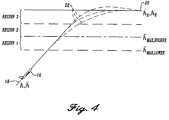
- the acceleration required to capture and hold a newly selected altitude h s corresponds to the previously discussed intermediate commanded vertical acceleration ⁇ ' c (from multiplier 34 in FIGURES 3a, 3b, and 3c). If the aircraft 16 is a substantial distance above or below a selected altitude h s , it should experience only minimal acceleration, since gradual and constant ascent or descent may be used to bring the aircraft 16 to the selected altitude. Such distances define region 1, shown in FIGURE 4.
- Region 2 of FIGURE 4 represents these distances.
- the value at multiplier 34 which is preferably related to natural frequency ⁇ n , is the key to controlling the resulting acceleration, since it is the multiplier of the error term E that results in the intermediate commanded vertical acceleration term ⁇ ' c .
- the present invention uses a combination of techniques to adjust the value of intermediate commanded vertical acceleration term ⁇ ' c , including varying the natural frequency ⁇ n and absolute limiting. Both of these techniques are discussed in detail below and are accomplished at the time of engagement.
- the natural frequency ⁇ n of the command processor is determined according to the position of the aircraft within the various regions, which in turn, are defined according to the selected altitude h s and/or selected vertical speed ⁇ s .
- the intermediate vertical acceleration term ⁇ ' c is adjusted to efficiently capture a selected altitude without exceeding appropriate limits of vertical acceleration.
- Region 1 is a linear engagement start region.
- the vertical position control system via the command processor will produce an elevator command that results in the experienced aircraft acceleration being between a lower maximum acceleration limit ⁇ max, lower and a higher maximum acceleration limit ⁇ max,higher .
- the altitudes bounding region 1 thus correspond to the vertical distance required in order to transition to the new flight path while experiencing vertical acceleration of between ⁇ max, lower and ⁇ max, higher .
- region 1 lies within the following altitudes: h s - 2 h ⁇ (0)- h ⁇ s 2 h ⁇ max,lower e ⁇ Region 1 altitudes ⁇ h s - 2 h ⁇ (0)- h ⁇ s 2 h ⁇ max,higher e
- ⁇ max lower is preferably a constant set to ⁇ 0.05g (i.e., ⁇ 1.6 ft/s 2 )
- ⁇ max higher is preferably a constant set to ⁇ 0.1g (i.e., ⁇ 3.2 ft/s 2 ,), the sign of either maximum acceleration depending on whether the aircraft is ascending or descending to capture the new flight path.
- ⁇ n 2 h ⁇ (0) - h ⁇ s h s - h (0)
- region 2 of FIGURE 8 may be mathematically expressed as lying between the following altitudes: h s - 2 h ⁇ (0)- h ⁇ s 2 h max,higher e ⁇ Region 2 altitudes ⁇ h s - h ⁇ (0)- h ⁇ s 2 2 h ⁇ max,higher
- the intermediate commanded vertical acceleration ⁇ ' c is preferably limited to the higher maximum desirable vertical acceleration.
- h ⁇ ' c (0) h ⁇ max,higher
- This limiting of intermediate commanded vertical acceleration is accomplished by the command processor by setting the value of intermediate commanded vertical acceleration equal to ⁇ max,higher when an altitude change command is initiated and the aircraft is in operational region 2.
- this is indicated in FIGURE 3c by a two-position switch 50.
- switch 50 changes state to supply a ⁇ max signal to the first integrator 36
- additional switches 52 and 54 of FIGURE 3c are activated so that the signal supplied to combiner 44 is zero (instead of the signal supplied by multiplier 43) and the signal supplied to combining unit 48 is also zero (instead of the signal supplied by multiplier 46).
- ⁇ n is allowed to continue at its last value, since the transfer function is interrupted by switches 50, 52, and 54, and ⁇ n no longer sects h c or c .
- the above actions cause the command processor to command a constant maximum vertical acceleration and to command a vertical speed command c and altitude command h c based upon first and second integrals, respectively, of the maximum commanded acceleration.
- h s - h ( t *) h ⁇ ( t *)- h ⁇ s 2 h ⁇ max
- ⁇ n h ⁇ ( t *)- h ⁇ s h s - h ( t *)
- t* the time at which equation (14) is satisfied.
- Region 3 of FIGURE 4 may be mathematically expressed as lying between the following altitudes: h s - h ⁇ (0)- h ⁇ s 2 2 h ⁇ max,higher ⁇ Region 3 altitudes ⁇ h s
- the intermediate commanded vertical acceleration ⁇ ' c is limited to the higher maximum desirable vertical acceleration and switches 50, 52 and 54 are switched on.
- the command processor 24 follows the logic shown in the preferred embodiment of a flow chart of FIGURE 5.
- the flow chart is useful in determining and setting initial condition values for terms of the command processor 24.
- the initial values of the following are set:
- the command processor checks whether the aircraft 18 is within region 2 at block 108. If so, block 110 allows the natural frequency ⁇ n to remain at its last value and sets the damping ratio ⁇ according to equations (7), (8), or (9). Additionally, the intermediate commanded vertical acceleration ⁇ ' c is set to the higher maximum desired acceleration ⁇ max, higher by switch 50 in FIGURE 3c, and switches 52 and 54 go to zero.
- the command processor continually checks in block 112 as to whether equation (14) is true, and when so, allows block 114 to set the natural frequency ⁇ n according to equation (15) and switches 50, 52, and 54 turned off. In either case, the command processor 24 returns at block 124 to compute values for commanded altitude h c and commanded vertical speed c .
- the vertical position control system 19 uses these values to calculate the elevator command ⁇ e .
- Block 116 sets the damping ratio ⁇ according to equations (7), (8), or (9), allows the natural frequency ⁇ n to remain at its last value sets the intermediate commanded vertical acceleration ⁇ ' c according to equation (15), and sets switches 50, 52, and 54 on.
- the command processor 24 continually checks as to whether equation (17) is true in block 118, and when so, allows block 120 to set the natural frequency according to equation (18) and the switches 50, 52, and 54 to off. In either case, the command processor 24 returns at block 124 to compute values for commanded altitude h c and commanded vertical speed c .
- the vertical position control system 19 uses these values to calculate the elevator command ⁇ e .
- the command processor initializes values and computes the appropriate variables at the time of engagement and throughout the vertical maneuver.
Landscapes
- Engineering & Computer Science (AREA)
- Aviation & Aerospace Engineering (AREA)
- Radar, Positioning & Navigation (AREA)
- Remote Sensing (AREA)
- Physics & Mathematics (AREA)
- General Physics & Mathematics (AREA)
- Automation & Control Theory (AREA)
- Control Of Position, Course, Altitude, Or Attitude Of Moving Bodies (AREA)
- Feedback Control In General (AREA)
Applications Claiming Priority (2)
| Application Number | Priority Date | Filing Date | Title |
|---|---|---|---|
| US08/441,284 US5695156A (en) | 1995-05-15 | 1995-05-15 | Aircraft vertical position control system |
| US441284 | 1995-05-15 |
Publications (2)
| Publication Number | Publication Date |
|---|---|
| EP0743584A1 true EP0743584A1 (de) | 1996-11-20 |
| EP0743584B1 EP0743584B1 (de) | 2004-03-03 |
Family
ID=23752289
Family Applications (1)
| Application Number | Title | Priority Date | Filing Date |
|---|---|---|---|
| EP95203000A Revoked EP0743584B1 (de) | 1995-05-15 | 1995-11-06 | Flugzeug-Regelsystem für vertikale Position |
Country Status (3)
| Country | Link |
|---|---|
| US (1) | US5695156A (de) |
| EP (1) | EP0743584B1 (de) |
| DE (1) | DE69532632T2 (de) |
Cited By (2)
| Publication number | Priority date | Publication date | Assignee | Title |
|---|---|---|---|---|
| US7853369B2 (en) * | 2006-12-05 | 2010-12-14 | Airbus France | Active pitch control method and device for an aircraft |
| RU2451970C1 (ru) * | 2011-02-09 | 2012-05-27 | Федеральное Государственное Автономное Образовательное Учреждение Высшего Профессионального Образования "Дальневосточный Федеральный Университет" (Двфу) | Способ управления движением динамического объекта по пространственной траектории |
Families Citing this family (13)
| Publication number | Priority date | Publication date | Assignee | Title |
|---|---|---|---|---|
| FR2754364B1 (fr) * | 1996-10-03 | 1998-11-27 | Aerospatiale | Procede et dispositif de guidage vertical d'un aeronef |
| US6282466B1 (en) | 1998-11-03 | 2001-08-28 | The Boeing Company | Method of automated thrust-based roll guidance limiting |
| US6711476B2 (en) | 2001-09-27 | 2004-03-23 | The Boeing Company | Method and computer program product for estimating at least one state of a dynamic system |
| US6591169B2 (en) | 2001-09-27 | 2003-07-08 | The Boeing Company | Method and computer program product for controlling the actuators of an aerodynamic vehicle |
| US6814330B2 (en) | 2002-12-12 | 2004-11-09 | The Boeing Company | Method and computer program product for controlling the control effectors of an aerodynamic vehicle |
| US8131410B2 (en) * | 2007-06-15 | 2012-03-06 | The Boeing Company | Quiet climb crew interface |
| US8774985B2 (en) | 2011-07-22 | 2014-07-08 | The Boeing Company | Systems and methods for generating a command trajectory |
| US8831799B1 (en) | 2013-04-04 | 2014-09-09 | The Boeing Company | Flight director flare guidance |
| US9595200B2 (en) | 2015-02-09 | 2017-03-14 | The Boeing Company | System and method for providing guidance during a flare maneuver of an aircraft |
| FR3044810A1 (fr) * | 2015-12-04 | 2017-06-09 | Airbus Operations Sas | Systeme d’aide a la gestion du vol d’un aeronef lors d’une phase d’atterrissage. |
| US10481615B2 (en) * | 2017-03-01 | 2019-11-19 | Bell Textron Inc. | Rotorcraft control mode transition smoothing |
| CN112558478B (zh) * | 2020-12-08 | 2022-06-17 | 中国商用飞机有限责任公司 | 一种民机自动驾驶仪高度改平功能控制方法和系统 |
| US12223848B2 (en) * | 2021-11-18 | 2025-02-11 | The 28Th Research Institute Of China Electronics Technology Group Corporation | Method for determining transition height elements in flight climbing stage based on constant value segment identification |
Citations (3)
| Publication number | Priority date | Publication date | Assignee | Title |
|---|---|---|---|---|
| US3596855A (en) * | 1968-04-11 | 1971-08-03 | Elliott Brothers London Ltd | Aircraft control system |
| US4377848A (en) * | 1980-10-16 | 1983-03-22 | Sperry Corporation | Altitude capture mode for aircraft automatic flight control system |
| US5117362A (en) * | 1989-12-15 | 1992-05-26 | Honeywell | Path capture forcing function generator for aircraft vertical axis control |
Family Cites Families (8)
| Publication number | Priority date | Publication date | Assignee | Title |
|---|---|---|---|---|
| US3545703A (en) * | 1967-11-01 | 1970-12-08 | Bendix Corp | System for controlling flight of aircraft to attain a predetermined altitude |
| US3627236A (en) * | 1970-06-30 | 1971-12-14 | Sperry Rand Corp | Automatic throttle control with airspeed anticipation |
| US4032093A (en) * | 1975-06-27 | 1977-06-28 | The Boeing Company | Adaptive energy management for vertical speed control of an aircraft |
| US4114842A (en) * | 1977-03-28 | 1978-09-19 | Sperry Rand Corporation | Acceleration limited preselect altitude capture and control |
| US4357663A (en) * | 1979-12-03 | 1982-11-02 | The Boeing Company | Method and apparatus for aircraft pitch and thrust axes control |
| WO1984001345A1 (en) * | 1982-09-30 | 1984-04-12 | Boeing Co | Total energy based flight control system |
| US4633404A (en) * | 1983-05-20 | 1986-12-30 | Sperry Corporation | Automatic deceleration of aircraft during descent |
| US5079711A (en) * | 1990-02-26 | 1992-01-07 | The Boeing Company | Aircraft high altitude vertical flight path and speed control system |
-
1995
- 1995-05-15 US US08/441,284 patent/US5695156A/en not_active Expired - Lifetime
- 1995-11-06 EP EP95203000A patent/EP0743584B1/de not_active Revoked
- 1995-11-06 DE DE69532632T patent/DE69532632T2/de not_active Expired - Lifetime
Patent Citations (3)
| Publication number | Priority date | Publication date | Assignee | Title |
|---|---|---|---|---|
| US3596855A (en) * | 1968-04-11 | 1971-08-03 | Elliott Brothers London Ltd | Aircraft control system |
| US4377848A (en) * | 1980-10-16 | 1983-03-22 | Sperry Corporation | Altitude capture mode for aircraft automatic flight control system |
| US5117362A (en) * | 1989-12-15 | 1992-05-26 | Honeywell | Path capture forcing function generator for aircraft vertical axis control |
Cited By (2)
| Publication number | Priority date | Publication date | Assignee | Title |
|---|---|---|---|---|
| US7853369B2 (en) * | 2006-12-05 | 2010-12-14 | Airbus France | Active pitch control method and device for an aircraft |
| RU2451970C1 (ru) * | 2011-02-09 | 2012-05-27 | Федеральное Государственное Автономное Образовательное Учреждение Высшего Профессионального Образования "Дальневосточный Федеральный Университет" (Двфу) | Способ управления движением динамического объекта по пространственной траектории |
Also Published As
| Publication number | Publication date |
|---|---|
| DE69532632D1 (de) | 2004-04-08 |
| EP0743584B1 (de) | 2004-03-03 |
| DE69532632T2 (de) | 2005-03-10 |
| US5695156A (en) | 1997-12-09 |
Similar Documents
| Publication | Publication Date | Title |
|---|---|---|
| EP0743584A1 (de) | Flugzeug-Regelsystem für vertikale Position | |
| US6158695A (en) | Method of speed protection and flare compensation for use with aircraft pitch control system | |
| EP0123664B1 (de) | Steuerungssystem mit einer, einer veränderlichen Kraft untergeordneten Handsteuerung | |
| EP0601016B1 (de) | Koordinierte kursabweichung bei niedrigen geschwindigkeiten für drehflügelflugzeug | |
| EP0253614B1 (de) | System zum Steuern des vertikalen Flugweges und der Fluggeschwindigkeit eines Flugzeuges | |
| EP0377913B1 (de) | Digitales adaptives Filter, das auf die Änderungsgeschwindigkeit eines Eingangssignals anspricht | |
| EP0600988B1 (de) | Koordinierte Kursabweichung bei hohen Geschwindigkeiten für Drehflügelflugzeug | |
| US4471439A (en) | Method and apparatus for aircraft pitch and thrust axes control | |
| EP0549014B1 (de) | Methode und Vorrichtung zur Regelung des Schubes eines Flugzeuges während des Steigfluges | |
| EP0125088B1 (de) | Flugkontrollsystem für Hubschrauber | |
| JPH0375399B2 (de) | ||
| US4956780A (en) | Flight path angle command flight control system for landing flare | |
| EP0601123A1 (de) | Modellunterstütze Geschwindigkeitsteuerung bei niedrigen Geschwindigkeiten für Drehflügelflugzeug. | |
| US4500967A (en) | Aircraft short-term roll attitude retention system | |
| EP0600991B1 (de) | Automatische trimmsteuerung zur koordinierten kursabweichung für ein drehflügel-flugzeug | |
| US5020747A (en) | Method and apparatus for controlling flare engagement height in automatic landing systems | |
| US4377848A (en) | Altitude capture mode for aircraft automatic flight control system | |
| EP0334476A2 (de) | Vorrichtung zum Erzeugen von Prozessregelungssignalen aus Prozessgrössensignalen | |
| EP0706681B1 (de) | System zur frequenzabhangigen modenunterdruckung fur flugzeuge | |
| JPH0567478B2 (de) | ||
| US5096146A (en) | Apparatus and methods for controlling commanded operation of an aircraft within a predetermined flight parameter limit | |
| EP0807574B1 (de) | Methode und Vorrichtung zur Verstärkungsanpassung eines Kurvenflugkoordinators in Abhängigkeit von der Landeklappenposition | |
| CN112558478B (zh) | 一种民机自动驾驶仪高度改平功能控制方法和系统 | |
| EP0224279B1 (de) | Vorrichtung und Verfahren zum Generieren von Steuerbefehlen für ein Flugzeug unter Verwendung einer Rückkopplung mit nichtlinearer Verstärkung | |
| EP0122718A2 (de) | Verfahren und Vorrichtung zur automatischen Flugsteuerung eines Flugzeuges |
Legal Events
| Date | Code | Title | Description |
|---|---|---|---|
| PUAI | Public reference made under article 153(3) epc to a published international application that has entered the european phase |
Free format text: ORIGINAL CODE: 0009012 |
|
| AK | Designated contracting states |
Kind code of ref document: A1 Designated state(s): DE FR GB |
|
| 17P | Request for examination filed |
Effective date: 19961202 |
|
| 17Q | First examination report despatched |
Effective date: 19991012 |
|
| GRAP | Despatch of communication of intention to grant a patent |
Free format text: ORIGINAL CODE: EPIDOSNIGR1 |
|
| GRAS | Grant fee paid |
Free format text: ORIGINAL CODE: EPIDOSNIGR3 |
|
| GRAA | (expected) grant |
Free format text: ORIGINAL CODE: 0009210 |
|
| AK | Designated contracting states |
Kind code of ref document: B1 Designated state(s): DE FR GB |
|
| REG | Reference to a national code |
Ref country code: GB Ref legal event code: FG4D |
|
| REF | Corresponds to: |
Ref document number: 69532632 Country of ref document: DE Date of ref document: 20040408 Kind code of ref document: P |
|
| ET | Fr: translation filed | ||
| PLBQ | Unpublished change to opponent data |
Free format text: ORIGINAL CODE: EPIDOS OPPO |
|
| PLBI | Opposition filed |
Free format text: ORIGINAL CODE: 0009260 |
|
| PLBQ | Unpublished change to opponent data |
Free format text: ORIGINAL CODE: EPIDOS OPPO |
|
| PLAB | Opposition data, opponent's data or that of the opponent's representative modified |
Free format text: ORIGINAL CODE: 0009299OPPO |
|
| PLBQ | Unpublished change to opponent data |
Free format text: ORIGINAL CODE: EPIDOS OPPO |
|
| PLBI | Opposition filed |
Free format text: ORIGINAL CODE: 0009260 |
|
| 26 | Opposition filed |
Opponent name: AIRBUS SAS Effective date: 20041117 |
|
| PLAX | Notice of opposition and request to file observation + time limit sent |
Free format text: ORIGINAL CODE: EPIDOSNOBS2 |
|
| PLAX | Notice of opposition and request to file observation + time limit sent |
Free format text: ORIGINAL CODE: EPIDOSNOBS2 |
|
| D26 | Opposition filed (deleted) | ||
| 26 | Opposition filed |
Opponent name: AIRBUS SAS Effective date: 20041202 |
|
| PLAQ | Examination of admissibility of opposition: information related to despatch of communication + time limit deleted |
Free format text: ORIGINAL CODE: EPIDOSDOPE2 |
|
| PLAR | Examination of admissibility of opposition: information related to receipt of reply deleted |
Free format text: ORIGINAL CODE: EPIDOSDOPE4 |
|
| PLBQ | Unpublished change to opponent data |
Free format text: ORIGINAL CODE: EPIDOS OPPO |
|
| PLAB | Opposition data, opponent's data or that of the opponent's representative modified |
Free format text: ORIGINAL CODE: 0009299OPPO |
|
| R26 | Opposition filed (corrected) |
Opponent name: AIRBUS SAS Effective date: 20041202 |
|
| PLAX | Notice of opposition and request to file observation + time limit sent |
Free format text: ORIGINAL CODE: EPIDOSNOBS2 |
|
| PLBB | Reply of patent proprietor to notice(s) of opposition received |
Free format text: ORIGINAL CODE: EPIDOSNOBS3 |
|
| PLAB | Opposition data, opponent's data or that of the opponent's representative modified |
Free format text: ORIGINAL CODE: 0009299OPPO |
|
| R26 | Opposition filed (corrected) |
Opponent name: AIRBUS SAS Effective date: 20041202 |
|
| APBP | Date of receipt of notice of appeal recorded |
Free format text: ORIGINAL CODE: EPIDOSNNOA2O |
|
| APAH | Appeal reference modified |
Free format text: ORIGINAL CODE: EPIDOSCREFNO |
|
| APBQ | Date of receipt of statement of grounds of appeal recorded |
Free format text: ORIGINAL CODE: EPIDOSNNOA3O |
|
| PGFP | Annual fee paid to national office [announced via postgrant information from national office to epo] |
Ref country code: FR Payment date: 20110105 Year of fee payment: 16 |
|
| PGFP | Annual fee paid to national office [announced via postgrant information from national office to epo] |
Ref country code: DE Payment date: 20101025 Year of fee payment: 16 |
|
| PGFP | Annual fee paid to national office [announced via postgrant information from national office to epo] |
Ref country code: GB Payment date: 20101022 Year of fee payment: 16 |
|
| REG | Reference to a national code |
Ref country code: DE Ref legal event code: R103 Ref document number: 69532632 Country of ref document: DE Ref country code: DE Ref legal event code: R064 Ref document number: 69532632 Country of ref document: DE |
|
| APBU | Appeal procedure closed |
Free format text: ORIGINAL CODE: EPIDOSNNOA9O |
|
| RDAE | Information deleted related to despatch of communication that patent is revoked |
Free format text: ORIGINAL CODE: EPIDOSDREV1 |
|
| RDAF | Communication despatched that patent is revoked |
Free format text: ORIGINAL CODE: EPIDOSNREV1 |
|
| RDAG | Patent revoked |
Free format text: ORIGINAL CODE: 0009271 |
|
| STAA | Information on the status of an ep patent application or granted ep patent |
Free format text: STATUS: PATENT REVOKED |
|
| 27W | Patent revoked |
Effective date: 20110407 |
|
| GBPR | Gb: patent revoked under art. 102 of the ep convention designating the uk as contracting state |
Effective date: 20110407 |
|
| REG | Reference to a national code |
Ref country code: DE Ref legal event code: R107 Ref document number: 69532632 Country of ref document: DE Effective date: 20111110 |