EP0743652B1 - Procédé et dispositif pour la manutention d'assemblages de combustibles nucléaires au sein d'un coeur de réacteur - Google Patents
Procédé et dispositif pour la manutention d'assemblages de combustibles nucléaires au sein d'un coeur de réacteur Download PDFInfo
- Publication number
- EP0743652B1 EP0743652B1 EP96420177A EP96420177A EP0743652B1 EP 0743652 B1 EP0743652 B1 EP 0743652B1 EP 96420177 A EP96420177 A EP 96420177A EP 96420177 A EP96420177 A EP 96420177A EP 0743652 B1 EP0743652 B1 EP 0743652B1
- Authority
- EP
- European Patent Office
- Prior art keywords
- assemblies
- assembly
- nuclear fuel
- mast
- handling
- Prior art date
- Legal status (The legal status is an assumption and is not a legal conclusion. Google has not performed a legal analysis and makes no representation as to the accuracy of the status listed.)
- Expired - Lifetime
Links
- 230000000712 assembly Effects 0.000 title claims description 61
- 238000000429 assembly Methods 0.000 title claims description 61
- 239000003758 nuclear fuel Substances 0.000 title claims description 13
- 238000000034 method Methods 0.000 title claims description 9
- 238000009434 installation Methods 0.000 title description 6
- 239000000446 fuel Substances 0.000 claims description 14
- 230000009471 action Effects 0.000 claims description 10
- 238000001816 cooling Methods 0.000 claims description 5
- 229920001971 elastomer Polymers 0.000 claims description 4
- 239000000806 elastomer Substances 0.000 claims description 4
- 230000008569 process Effects 0.000 claims description 4
- 229910000831 Steel Inorganic materials 0.000 claims description 3
- 230000006835 compression Effects 0.000 claims description 3
- 238000007906 compression Methods 0.000 claims description 3
- 239000007788 liquid Substances 0.000 claims description 3
- 230000002093 peripheral effect Effects 0.000 claims description 3
- 239000010959 steel Substances 0.000 claims description 3
- 239000007787 solid Substances 0.000 claims 3
- 230000007246 mechanism Effects 0.000 description 9
- 238000006073 displacement reaction Methods 0.000 description 7
- 230000004048 modification Effects 0.000 description 5
- 238000012986 modification Methods 0.000 description 5
- XLYOFNOQVPJJNP-UHFFFAOYSA-N water Substances O XLYOFNOQVPJJNP-UHFFFAOYSA-N 0.000 description 4
- 239000002826 coolant Substances 0.000 description 2
- 239000012530 fluid Substances 0.000 description 2
- 240000005561 Musa balbisiana Species 0.000 description 1
- 238000012550 audit Methods 0.000 description 1
- 235000021015 bananas Nutrition 0.000 description 1
- 238000006243 chemical reaction Methods 0.000 description 1
- 230000008878 coupling Effects 0.000 description 1
- 238000010168 coupling process Methods 0.000 description 1
- 238000005859 coupling reaction Methods 0.000 description 1
- 230000003247 decreasing effect Effects 0.000 description 1
- 238000010586 diagram Methods 0.000 description 1
- 230000000694 effects Effects 0.000 description 1
- 230000005484 gravity Effects 0.000 description 1
- 230000001939 inductive effect Effects 0.000 description 1
- 238000006386 neutralization reaction Methods 0.000 description 1
- 238000005457 optimization Methods 0.000 description 1
- 210000000056 organ Anatomy 0.000 description 1
- 230000005855 radiation Effects 0.000 description 1
- 230000000284 resting effect Effects 0.000 description 1
- 230000009182 swimming Effects 0.000 description 1
Images




Classifications
-
- G—PHYSICS
- G21—NUCLEAR PHYSICS; NUCLEAR ENGINEERING
- G21C—NUCLEAR REACTORS
- G21C19/00—Arrangements for treating, for handling, or for facilitating the handling of, fuel or other materials which are used within the reactor, e.g. within its pressure vessel
- G21C19/18—Apparatus for bringing fuel elements to the reactor charge area, e.g. from a storage place
-
- G—PHYSICS
- G21—NUCLEAR PHYSICS; NUCLEAR ENGINEERING
- G21C—NUCLEAR REACTORS
- G21C19/00—Arrangements for treating, for handling, or for facilitating the handling of, fuel or other materials which are used within the reactor, e.g. within its pressure vessel
- G21C19/16—Articulated or telescopic chutes or tubes for connection to channels in the reactor core
-
- Y—GENERAL TAGGING OF NEW TECHNOLOGICAL DEVELOPMENTS; GENERAL TAGGING OF CROSS-SECTIONAL TECHNOLOGIES SPANNING OVER SEVERAL SECTIONS OF THE IPC; TECHNICAL SUBJECTS COVERED BY FORMER USPC CROSS-REFERENCE ART COLLECTIONS [XRACs] AND DIGESTS
- Y02—TECHNOLOGIES OR APPLICATIONS FOR MITIGATION OR ADAPTATION AGAINST CLIMATE CHANGE
- Y02E—REDUCTION OF GREENHOUSE GAS [GHG] EMISSIONS, RELATED TO ENERGY GENERATION, TRANSMISSION OR DISTRIBUTION
- Y02E30/00—Energy generation of nuclear origin
- Y02E30/30—Nuclear fission reactors
Definitions
- the invention relates to a method and a device for enabling handling of nuclear fuel assemblies within a reactor core, and more specifically, the loading of such a reactor.
- the core of a nuclear reactor consists of fuel rods or needles grouped together to form assemblies, which can be handled independently of each other other.
- These assemblies are positioned side by side, generally vertically, within an internal and rigid structure, namely the tank of the reactor substantially comprising towards the bottom a box spring or plate heart, provided with contiguous receptacles called locations, intended to receive the base of said assemblies thus formed.
- this box spring or heart plate is also provided with through holes intended to allow circulation within assemblies of a cooling and / or slowing down fluid of the neutrons emitted during nuclear reactions ensuring the release of energy.
- this new machine fulfills the objective assigned to it for a large number of assemblies, on the other hand, given its very principle of operation, its use induces the neutralization of certain locations of the bed base which cannot be filled with such a tool. In fact, typically, about 25% of boxspring locations cannot be filled with such a tool. In fact, and in order to allow the filling of these locations, it has been proposed to add to the machines traditional specific tools and accessories, but whose use requires special precautions, heavy to implement, especially in water or liquid cooling and / or slowing down.
- the invention proposes to overcome these drawbacks. It aims first of all at a process for charging the core of a nuclear reactor regardless of the state of deformation of assemblies which constitute it and whatever the location to be filled.
- This process consists, after having coupled the end of the telescopic mast secured to the handling machine, at the upper end of a nuclear fuel assembly, tilting said mast, and therefore the corresponding assembly to which it is coupled, so as to first present the foot of said assembly at the desired location of the box spring receipt of said assemblies within the reactor core, then to induce the straightening of said assembly until reaching a vertical position of so as to tilt the foot of said assembly within the location considered while by synchronizing the restoration of the verticality of the mast with the moving the loading machine.
- the carriage is provided with a plurality of members, likely to act on the plate of the telescopic mast, so as to tilt it relative to the vertical.
- the telescopic mast is secured to the carriage by means of a extension consisting of two parts, respectively a lower part secured to the carriage, and an upper part secured to the part upper mast, said parts cooperating with each other in such a way so as to prohibit any movement of one with respect to the other during the normal machine operation, but likely to be able to deviate from each other in a vertical direction or a direction neighbor, so as to result in an inclination of the upper part with respect to the lower part of said extension.
- this displacement is ensured by means of a cam housed within a stop, capable of translate vertically within a guide box, said stop acting on the upper part of the riser under the action of said cam.
- these attitude modification members are at number of four, are distributed at 90 ° to each other and are likely to act either individually or simultaneously to to ensure the inclination of the telescopic mast, and starting from the assembly to which it is coupled in eight directions distributed at 45 ° from one another.
- these cam mechanisms are replaced by cylinders also arranged at 90 ° to each other others, and capable of being operated two by two.
- the upper part of the extension has a periphery ring gear within which is likely to mesh a pinion toothed, in order to ensure the rotation of the mast and the fuel assembly to which it is coupled. This rotation can be used, if necessary, to perfect the presentation of the base of the fuel assembly opposite its location, especially in the event of a twist.
- the base of the mast is assimilated to a virtual ball joint, likely to tilt according to infinite direction relative to the vertical, and whose displacement possible from the base describes a half-sphere.
- said base rests on peripheral pads, typically four or more, said studs being made of an elastomer - steel laminate, having a high shear deformation capacity, and on the contrary a low deformation capacity in compression.
- said base is actuated in displacement by means of actuators acting at the periphery of the base, the number of actuators being at least two, oriented 90 degrees to each other, and whose action conjugate leads to the desired inclination of the base therefore of the mast telescopic.
- actuators advantageously consist of cylinders electric short stroke, themselves mounted on an elastomeric ball joint, so as to adapt their orientation according to the orientation of the base from which they are at the origin.
- Figure 1 is a schematic perspective representation of the device according to the invention, acting according to the traditional method.
- Figure 2 is a representation similar to Figure 1 in which the device according to the invention makes the mast work according to a direction inclined to the vertical.
- Figure 3 is a schematic top view of the carriage device control according to a first embodiment of the invention.
- FIG. 4 is a partial side view of the control cart Figure 3.
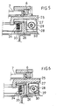
- Figures 5 and 6 are schematic sectional views of the organs inclination of the mast of the device according to the first form of realization of the invention.
- Figure 7 is a schematic perspective representation overview of a second embodiment of the invention.
- FIG. 8 is a more detailed schematic representation of the mast base according to the second embodiment of the invention.
- Figure 9 is a schematic representation of one of the actuators of Figures 7 and 8.
- FIG. 1 therefore represents a block diagram representing the handling machine using the device of the invention.
- This machine (1) has a structure or bridge (2) provided with rollers (3) for circulation on rails carried by the edges (4) of the swimming pool in which the reactor vessel (not shown) is immersed nuclear type, for example pressurized water (PWR).
- PWR pressurized water
- the structure (2) itself carries rails guiding a carriage (5), movable in a direction perpendicular to the direction of movement of the structure.
- the carriage (5) carries a mast vertical (7) by means of a mechanism (6) for driving rotation about the axis of said mast, this mechanism (6) being typically consisting of a toothed crown, which can best be seen on the Figure 4.
- the mast (7) is integral with the carriage and comprises various members command and control (not shown) allowing deployment and the folding back of a telescopic tube (8), coaxial with the mast (7).
- the lower end of the telescopic tube (8) has a grapnel or equivalent gripping system (11), intended to grip the end top of an assembly (10) of fuel elements (12), in order to allow either its loading or its unloading respectively at inside and outside the reactor core.
- These fuel assemblies are known per se and include their lower end a foot (15) capable of cooperating with positioning pins (14), formed within a box spring (13), itself positioned substantially in the bottom of the reactor vessel.
- These assemblies (10) are positioned side by side in a vertical direction and are arranged substantially in an octagonal section, comprising typically 156 assemblies for a 900 MWe reactor. Said assemblies are arranged so that the coolant, the water in the example described, can circulate between the needles (12) constituting said assemblies (10).
- the mast (7) is tilted and therefore the telescopic tube (8) and the assembly (10) to which it is coupled, so as to present all first the foot (15) of the assembly considered at the location of the box spring (13) to which it is assigned, that is to say that the pins of said location are partially engaged in the holes provided for this effect in the foot of said assembly.
- This inclination of the assembly thus makes it possible to overcome the possible deformations of neighboring assemblies for installation of the assembly considered, and therefore eliminates any interference from friction or volume due to such deformations.
- the mast (7) is secured to the carriage (5) by means of an extension consisting of two parts, respectively an upper part (25) integral of the mast (7), and a lower part (26) integral with the carriage (5). These two parts are closely intertwined with each other, but can however deviate in a vertical direction one with respect to the other. To do this, the carriage (5) has four modification members tilt (17,, 20, 21), distributed at 90 ° two by two, and so regular around the mast (7) as can be seen in Figure 3.
- These members each include a stop (27), capable of being translate vertically within a guide box (28) integral with the lower part (26) of the extension.
- the upper face of this stop is capable of cooperating with the upper part (25) of the extension of the mast (7).
- This stop (27) is pierced with a light (29), extending substantially horizontally and made up of two discs not concentric.
- a cam (30), integral with a horizontal axis (16), is likely to rotate, under the action of this axis within this light.
- the axis (16) is rotated by means of a lever (31) capable of to describe an arc of approximately 90 ° as can be seen on the Figure 4.
- This lever is itself moved by the action of a jack (32) itself powered by a direct current electric motor (33).
- a direct current electric motor 33.
- Each of the motor assemblies (31, 32, 33) of each modification member of inclination (17, 19, 20, 21) has been represented in FIG. 3 by the references (18, 22, 23, 24).
- Each of the tilt modification members (17, 19, 20, 21) is can be operated independently of each other, or even simultaneously in torque depending on the desired inclination and the direction of this tilt.
- the mechanisms with cam and stopper described above can be replaced by four cylinders positioned at each corner of the control carriage (5), like said mechanisms, and can then be actuated two by two.
- the base (36) of the telescopic mast (7, 8) is assimilated to a virtual ball joint, capable of tilting according to infinite direction from the vertical.
- a broken line (42) the possible displacement of the end lower of this ball joint, namely typically a half-sphere.
- the base (36) rests for this purpose on peripheral pads (37), by example four in number, regularly distributed around the base, and attached to the loading machine. However, one could conceive a higher number of plots, until reaching a continuum.
- These studs (37) consist of an elastomer - steel laminate, with a high capacity for shear deformation, and at on the contrary, a low capacity for deformation in compression.
- Such laminates are for example marketed by companies under French law TECHLAM or PAULSTRA. They make it possible to transmit efforts very important, while allowing equally large deflections, while removing a large number of mechanical elements traditional, usually used to achieve the same travel.
- the base (36) of the telescopic mast (7, 8) is actuated by displacement by means of actuators (41) acting at the level of the periphery of the base.
- actuators at least two in number, oriented 90 degrees to each other, are advantageously constituted by short-stroke electric cylinders, themselves mounted on an elastomeric ball joint (43), of the same type as the studs (37), such so as to adapt their orientation according to the orientation of the base which they are at the origin.
- They comprise an electric motor (44) actuating, possibly via a gear motor, a system screw-nut (45), backlash, high efficiency, comprising rollers. between screw and nut, ensuring the modification of the inclination of the base, by means of another ball joint (46), secured to the base (36).
- four actuators can be provided, distributed at 90 degrees two by two, and mounted in opposition, and enslaved in such a way that the base (36) of the telescopic mast can tilt in a infinity of directions.
- the base (36) is secured to the loading via an anti-rotation bar (40), as well as can see it in Figure 8.
- the telescopic mast (7, 8) can rotate under the action a pinion (39) rotated by a mechanism (38) integral with the base (36), said pinion meshing in the ring gear (6) formed above the base (36) of said mast.
- Ball crowns (6) is placed on the base (36). It allows rotation of said mast.
Landscapes
- Physics & Mathematics (AREA)
- Engineering & Computer Science (AREA)
- Plasma & Fusion (AREA)
- General Engineering & Computer Science (AREA)
- High Energy & Nuclear Physics (AREA)
- Monitoring And Testing Of Nuclear Reactors (AREA)
Description
- une machine de manutention susceptible de se déplacer dans un plan horizontal au-dessus du coeur de réacteur, et munie d'un chariot de commande, également susceptible de se déplacer selon une direction horizontale ;
- un mât télescopique, fixé par son extrémité supérieure audit chariot, et muni à son extrémité inférieure d'un organe de fixation et de couplage à l'extrémité supérieure d'un assemblage de combustibles.
Claims (9)
- Procédé pour la manutention d'assemblages (10) de combustibles nucléaires au sein du coeur d'un réacteur nucléaire mettant en oeuvre une machine de chargement (1) susceptible de se déplacer selon un plan horizontal surplombant ledit réacteur, et munie d'un mât (7) et d'un tube télescopique (8) coaxiaux, destinés à saisir lesdits assemblages (10) par leur extrémité supérieure, ledit mât (7), et partant l'assemblage correspondant auquel il est couplé étant incliné de telle sorte à présenter en premier lieu le pied (15) dudit assemblage à l'emplacement souhaité du sommier (13) de réception desdits assemblages au sein du coeur du réacteur, caractérisé en ce qu'il consiste à déplacer la machine de chargement (1) en synchronisme avec le redressement dudit assemblage jusqu'à atteindre une position verticale de celui-ci.
- Dispositif pour la manutention d'assemblages (10) de combustibles nucléaires, notamment dans le coeur d'un réacteur nucléaire comportant un sommier (13) destiné à recevoir lesdits assemblages selon une orientation verticale, ledit sommier étant muni de zones de réception ou emplacements contigus des pieds desdits assemblages et comprenant également des orifices destinés à permettre la circulation d'un fluide de refroidissement et/ou de ralentissement des neutrons, comprenant :caractérisé en ce que la solidarisation du mât télescopique (7, 8) au chariot de commande (5) s'effectue au moyen d'une réhausse constituée de deux parties, respectivement une partie inférieure (26) solidaire du chariot (5), et une partie supérieure (25) solidaire de la partie supérieure du mât (7), lesdites parties coopérant l'une avec l'autre de telle sorte à interdire tout mouvement de l'une par rapport à l'autre en fonctionnement normal dudit dispositif, ladite partie supérieure (25) étant susceptible de s'écarter de la partie inférieure (26) selon une direction verticale ou une direction voisine, de telle sorte à permettre son inclinaison relativement à ladite partie inférieure.une machine de manutention (1, 2) susceptible de se déplacer dans un plan horizontal au-dessus du coeur de réacteur, et munie d'un chariot de commande (5), également susceptible de se déplacer selon une direction horizontale, et munie d'une pluralité d'organes (17, 19, 20, 21), susceptibles d'agir sur l'assiette du mât télescopique, de telle sorte à incliner celui-ci par rapport à la verticale ;un mât télescopique (7, 8), fixé par son extrémité supérieure audit chariot (5), et muni à son extrémité inférieure d'un organe de fixation et de couplage (11) à l'extrémité supérieure d'un assemblage de combustibles,
- Dispositif pour la manutention d'assemblages (10) de combustibles nucléaires selon la revendication 2, caractérisé en ce que les organes de modification d'assiette (17, 19, 20, 21) sont au nombre de quatre, répartis à 90° l'un par rapport à l'autre sur le chariot (5) et autour du mât télescopique (7, 8), et sont susceptibles d'agir soit individuellement soit simultanément afin d'assurer l'inclinaison du mât télescopique, et partant de l'assemblage auquel il est couplé selon huit directions réparties à 45° l'une de l'autre.
- Dispositif pour la manutention d'assemblages (10) de combustibles nucléaires selon l'une des revendications 2 et 3, caractérisé en ce que l'écartement de la partie supérieure (25) par rapport à la partie inférieure (26) de la réhausse s'effectue sous l'action d'une butée (27), susceptible de se translater verticalement au sein d'un boítier de guidage (28) solidaire de ladite partie inférieure (26), la translation de ladite butée (27) s'effectuant sous l'action de la rotation d'une came (30) au sein d'une lumière (29) ménagée au sein de ladite butée (27), ladite butée (27) coopérant avec la partie supérieure de la réhausse (25) par sa face supérieure.
- Dispositif pour la manutention d'assemblages (10) de combustibles nucléaires selon la revendication 4, caractérisé en ce que la rotation de la came (30) au sein de la lumière (29) de la butée (27) s'effectue sous l'action d'un axe horizontal (16), lui-même mû en rotation au moyen d'un levier (31), dont l'actionnement est assuré par un ensemble moteur électrique (33) - vérin (32).
- Dispositif pour la manutention d'assemblages (10) de combustibles nucléaires selon la revendication 2, caractérisé en ce que l'écartement de la partie supérieure (25) par rapport à la partie inférieure (26) de la réhausse s'effectue sous l'action d'un vérin à actionnement vertical.
- Dispositif pour la manutention d'assemblages (10) de combustibles nucléaires, notamment dans le coeur d'un réacteur nucléaire comportant un sommier (13) destiné à recevoir lesdits assemblages selon une orientation verticale, ledit sommier étant muni de zones ou de réception ou emplacements contigus des pieds desdits assemblages et comprenant également des orifices destinés à permettre la circulation d'un fluide de refroidissement et/ou de ralentissement des neutrons, comprenant :caractérisé en ce que l'embase (36) du mât téléscopique (7, 8) repose sur une pluralité de plots périphériques (37) régulièrement répartis autour de l'embase, et fixés sur la machine de manutention, lesdits plots (37) étant chacun constitués d'un lamellé élastomère - acier, présentant une grande capacité de déformation en cisaillement, et au contraire une faible capacité de déformation en compression, et en ce que l'embase (36) est actionnée en déplacement au moyen d'actionneurs (41) agissant au niveau de la périphérie de l'embase.une machine de manutention (1, 2) susceptible de se déplacer dans un plan horizontal au-dessus du coeur de réacteur, et munie d'un chariot de commande (5), également susceptible de se déplacer selon une direction horizontale, et muni d'une pluralité d'organes (17, 19, 20, 21), susceptibles d'agir sur l'assiette du mât télescopique, de telle sorte à incliner celui-ci par rapport à la verticale;un mât télescopique (7, 8), fixé par son extrémité supérieure audit chariot (5), et muni à son extrémité inférieure d'un organe de fixation et de couplage (11) à l'extrémité supérieure d'un assemblage de combustibles,
- Dispositif pour la manutention d'assemblages (10) de combustibles nucléaires selon la revendication 7, caractérisé en ce que les actionneurs (41) sont au moins au nombre de deux, orientés à 90 degrés l'un par rapport à l'autre, et sont constitués par des vérins électriques à faible course.
- Dispositif pour la manutention d'assemblages (10) de combustibles nucléaires selon la revendication 7, caractérisé en ce que les vérins constitutifs des actionneurs (41) sont montés sur une rotule élastomère (43), de telle sorte à adapter leur orientation en fonction de l'orientation de l'embase dont ils sont à l'origine.
Applications Claiming Priority (2)
| Application Number | Priority Date | Filing Date | Title |
|---|---|---|---|
| FR9506078A FR2734391B1 (fr) | 1995-05-17 | 1995-05-17 | Procede et dispositif pour la manutention d'assemblages de combustibles nucleaires au sein d'un coeur de reacteur |
| FR9506078 | 1995-05-17 |
Publications (2)
| Publication Number | Publication Date |
|---|---|
| EP0743652A1 EP0743652A1 (fr) | 1996-11-20 |
| EP0743652B1 true EP0743652B1 (fr) | 1999-04-14 |
Family
ID=9479257
Family Applications (1)
| Application Number | Title | Priority Date | Filing Date |
|---|---|---|---|
| EP96420177A Expired - Lifetime EP0743652B1 (fr) | 1995-05-17 | 1996-05-15 | Procédé et dispositif pour la manutention d'assemblages de combustibles nucléaires au sein d'un coeur de réacteur |
Country Status (5)
| Country | Link |
|---|---|
| EP (1) | EP0743652B1 (fr) |
| CN (1) | CN1160739C (fr) |
| DE (1) | DE69602051D1 (fr) |
| FR (1) | FR2734391B1 (fr) |
| ZA (1) | ZA963948B (fr) |
Families Citing this family (14)
| Publication number | Priority date | Publication date | Assignee | Title |
|---|---|---|---|---|
| CN101740146B (zh) * | 2008-11-20 | 2012-06-27 | 中国核电工程有限公司 | 双工位抓具 |
| CN101546614B (zh) * | 2009-04-21 | 2012-07-04 | 中国原子能科学研究院 | 一种破损组件密封罐抓具 |
| CN101625906B (zh) * | 2009-07-22 | 2012-07-25 | 中国广东核电集团有限公司 | 一种控制棒处理的操作方法及其处理工具 |
| CN102097140B (zh) * | 2009-12-11 | 2013-02-13 | 上海核工程研究设计院 | 压水堆燃料水下运输小车及倾翻装置 |
| ITGE20100078A1 (it) * | 2010-07-20 | 2012-01-21 | Ts R & D S R L | Struttura di sostegno |
| EA201100214A1 (ru) * | 2011-01-31 | 2011-08-30 | Зао "Диаконт" | Система для защиты рабочего органа перегрузочной машины от столкновения с препятствием |
| CN103594134B (zh) * | 2012-08-15 | 2016-05-11 | 广东核电合营有限公司 | 一种核电站堆芯燃料组件的装载方法 |
| CN103811086B (zh) * | 2012-11-09 | 2016-05-04 | 中国广核集团有限公司 | 核电站堆芯燃料组件的换料监视方法和系统 |
| US9275765B2 (en) * | 2013-01-15 | 2016-03-01 | Westinghouse Electric Company Llc | Method and apparatus for the shielded relocation of a nuclear component |
| US10593436B2 (en) * | 2013-11-21 | 2020-03-17 | Terrapower, Llc | Method and system for generating a nuclear reactor core loading distribution |
| DE102015217276B4 (de) * | 2015-09-10 | 2020-07-09 | Rwe Power Aktiengesellschaft | Anordnung zur Ausrichtung von Brennelementen in einem Kernbehälter eines Kernreaktors sowie Verfahren zur Ausrichtung von Brennelementen eines Kernreaktors in ihrer Einbaulage innerhalb eines Kernbehälters |
| CN106328231B (zh) * | 2016-11-14 | 2018-05-08 | 清华大学天津高端装备研究院 | 一种燃料组件抓取联动装置 |
| CN113620169A (zh) * | 2020-04-21 | 2021-11-09 | 广东博鼎建筑科技有限公司 | 一种建筑用行车及建筑设备 |
| GB2588842A (en) * | 2020-07-23 | 2021-05-12 | Rolls Royce Plc | Nuclear refuelling device |
Family Cites Families (7)
| Publication number | Priority date | Publication date | Assignee | Title |
|---|---|---|---|---|
| FR2588689B1 (fr) * | 1985-10-11 | 1987-12-24 | Fragema Framatome & Cogema | Machine de manutention d'assemblage combustible nucleaire et procede de chargement de reacteur en comportant application |
| FR2614128B1 (fr) * | 1987-04-15 | 1992-06-12 | Electricite De France | Outil d'aide au chargement des assemblages combustibles d'un reacteur nucleaire a eau pressurisee 1300 mw |
| JPS6454400A (en) * | 1987-08-26 | 1989-03-01 | Mitsubishi Heavy Ind Ltd | Crane for handling nuclear reactor fuel assembly |
| FR2641894B1 (fr) * | 1988-12-28 | 1991-04-26 | Framatome Sa | Dispositif de support et de positionnement de moyens de controle et d'outillages d'intervention sur des assemblages combustibles |
| JPH02208599A (ja) * | 1989-02-09 | 1990-08-20 | Mitsubishi Heavy Ind Ltd | 原子炉用核燃料移送設備 |
| US5156803A (en) * | 1991-02-25 | 1992-10-20 | Niagara Mohawk Power Corporation | Apparatus for inspection of a reactor vessel |
| FR2681466B1 (fr) * | 1991-09-17 | 1994-06-10 | Framatome Sa | Grappin orientable de manutention d'assemblage combustible nucleaire. |
-
1995
- 1995-05-17 FR FR9506078A patent/FR2734391B1/fr not_active Expired - Fee Related
-
1996
- 1996-05-15 EP EP96420177A patent/EP0743652B1/fr not_active Expired - Lifetime
- 1996-05-15 DE DE69602051T patent/DE69602051D1/de not_active Expired - Lifetime
- 1996-05-17 ZA ZA963948A patent/ZA963948B/xx unknown
- 1996-05-17 CN CNB961084219A patent/CN1160739C/zh not_active Expired - Fee Related
Also Published As
| Publication number | Publication date |
|---|---|
| ZA963948B (en) | 1996-11-25 |
| FR2734391A1 (fr) | 1996-11-22 |
| FR2734391B1 (fr) | 1997-07-18 |
| CN1145523A (zh) | 1997-03-19 |
| CN1160739C (zh) | 2004-08-04 |
| DE69602051D1 (de) | 1999-05-20 |
| EP0743652A1 (fr) | 1996-11-20 |
Similar Documents
| Publication | Publication Date | Title |
|---|---|---|
| EP0743652B1 (fr) | Procédé et dispositif pour la manutention d'assemblages de combustibles nucléaires au sein d'un coeur de réacteur | |
| EP0220117B1 (fr) | Machine de manutention d'assemblage combustible nucléaire et procédé de chargement de réacteur en comportant application | |
| EP0278799B1 (fr) | Coeur d'un réacteur nucléaire et procédé de chargement de ce coeur | |
| FR2848717A1 (fr) | Procede et dispositif de manutention d'un tube-guide des equipements internes superieurs d'un reacteur nucleaire | |
| BE1006517A3 (fr) | Dispositif d'usinage sous eau d'une grille-entretoise d'un assemblage combustible pour reacteur nucleaire. | |
| FR2681466A1 (fr) | Grappin orientable de manutention d'assemblage combustible nucleaire. | |
| EP1141967B1 (fr) | Installation de chargement de crayons de combustible dans un assemblage de combustible nucleaire | |
| FR2519178A1 (fr) | Faisceau d'elements combustibles avec barres absorbantes | |
| FR2725298A1 (fr) | Coeur d'un reacteur nucleaire a eau sous pression et embout superieur d'un assemblage de combustible du coeur | |
| EP0055647B1 (fr) | Machine pour le contrôle sur leur poste de stockage des équipements internes d'un réacteur nucléaire | |
| EP0151082B1 (fr) | Dispositif de pilotage du coeur d'un réacteur nucléaire | |
| EP0696806B1 (fr) | Installation pour la mise en place d'assemblages de combustible nucléaire | |
| EP0026142B1 (fr) | Dispositif d'accouplement et de désaccouplement à distance de deux éléments de grande longueur disposés coaxialement et bout à bout | |
| FR3081437A1 (fr) | Palonnier pour aeronef a module principal monobloc et amovible. | |
| EP0589792B1 (fr) | Dispositif de manutention de faisceaux tubulaires pour échangeurs thermiques | |
| FR2656458A1 (fr) | Dispositif de support et de positionnement d'un moyen d'intervention dans une zone determinee du cloisonnement du cóoeur d'un reacteur nucleaire a eau sous pression. | |
| EP0081431A1 (fr) | Dispositif de fixation d'un assemblage combustible sur la plaque inférieure de support du coeur, dans un réacteur nucléaire | |
| EP0638198B1 (fr) | Dispositif porte-outils pour un couvercle de cuve de reacteur nucleaire | |
| FR2833401A1 (fr) | Procede et dispositif de blocage d'un assemblage combustible nucleaire dans un logement | |
| EP0095417A1 (fr) | Dispositif de commande des barres absorbantes dans un système de pilotage d'un réacteur nucléaire | |
| EP0216665B1 (fr) | Elément absorbant pour réacteur nucléaire à neutrons rapides | |
| EP0056753A1 (fr) | Dispositif élévateur pour plate-forme marine auto-élévatrice | |
| WO2003019577A1 (fr) | Installation pour la mise en place d'assemblages de combustible nucleaire | |
| FR2706983A1 (en) | Orientable and retractable lighting device for a cavity containing radioactive materials | |
| FR2931581A1 (fr) | Procede de remplacement des broches de centrage des tubes de guides de grappes sur la plaque superieure de coeur d'un reacteur nucleaire |
Legal Events
| Date | Code | Title | Description |
|---|---|---|---|
| PUAI | Public reference made under article 153(3) epc to a published international application that has entered the european phase |
Free format text: ORIGINAL CODE: 0009012 |
|
| AK | Designated contracting states |
Kind code of ref document: A1 Designated state(s): BE CH DE ES FR LI |
|
| 17P | Request for examination filed |
Effective date: 19961130 |
|
| 17Q | First examination report despatched |
Effective date: 19971229 |
|
| GRAG | Despatch of communication of intention to grant |
Free format text: ORIGINAL CODE: EPIDOS AGRA |
|
| GRAG | Despatch of communication of intention to grant |
Free format text: ORIGINAL CODE: EPIDOS AGRA |
|
| GRAH | Despatch of communication of intention to grant a patent |
Free format text: ORIGINAL CODE: EPIDOS IGRA |
|
| GRAH | Despatch of communication of intention to grant a patent |
Free format text: ORIGINAL CODE: EPIDOS IGRA |
|
| GRAA | (expected) grant |
Free format text: ORIGINAL CODE: 0009210 |
|
| AK | Designated contracting states |
Kind code of ref document: B1 Designated state(s): BE CH DE ES FR LI |
|
| PG25 | Lapsed in a contracting state [announced via postgrant information from national office to epo] |
Ref country code: ES Free format text: THE PATENT HAS BEEN ANNULLED BY A DECISION OF A NATIONAL AUTHORITY Effective date: 19990414 |
|
| REG | Reference to a national code |
Ref country code: CH Ref legal event code: EP |
|
| REF | Corresponds to: |
Ref document number: 69602051 Country of ref document: DE Date of ref document: 19990520 |
|
| PG25 | Lapsed in a contracting state [announced via postgrant information from national office to epo] |
Ref country code: DE Free format text: LAPSE BECAUSE OF FAILURE TO SUBMIT A TRANSLATION OF THE DESCRIPTION OR TO PAY THE FEE WITHIN THE PRESCRIBED TIME-LIMIT Effective date: 19990715 |
|
| PLBE | No opposition filed within time limit |
Free format text: ORIGINAL CODE: 0009261 |
|
| STAA | Information on the status of an ep patent application or granted ep patent |
Free format text: STATUS: NO OPPOSITION FILED WITHIN TIME LIMIT |
|
| 26N | No opposition filed | ||
| PGFP | Annual fee paid to national office [announced via postgrant information from national office to epo] |
Ref country code: CH Payment date: 20060512 Year of fee payment: 11 |
|
| REG | Reference to a national code |
Ref country code: CH Ref legal event code: PL |
|
| PG25 | Lapsed in a contracting state [announced via postgrant information from national office to epo] |
Ref country code: LI Free format text: LAPSE BECAUSE OF NON-PAYMENT OF DUE FEES Effective date: 20070531 Ref country code: CH Free format text: LAPSE BECAUSE OF NON-PAYMENT OF DUE FEES Effective date: 20070531 |
|
| REG | Reference to a national code |
Ref country code: FR Ref legal event code: PLFP Year of fee payment: 20 |
|
| PGFP | Annual fee paid to national office [announced via postgrant information from national office to epo] |
Ref country code: FR Payment date: 20150529 Year of fee payment: 20 Ref country code: BE Payment date: 20150529 Year of fee payment: 20 |