EP0743713A2 - Haltevorrichtung und Masseschiene für einen Verbindungsblock - Google Patents
Haltevorrichtung und Masseschiene für einen Verbindungsblock Download PDFInfo
- Publication number
- EP0743713A2 EP0743713A2 EP96303418A EP96303418A EP0743713A2 EP 0743713 A2 EP0743713 A2 EP 0743713A2 EP 96303418 A EP96303418 A EP 96303418A EP 96303418 A EP96303418 A EP 96303418A EP 0743713 A2 EP0743713 A2 EP 0743713A2
- Authority
- EP
- European Patent Office
- Prior art keywords
- bracket
- ground bar
- support posts
- mounting bracket
- ground
- Prior art date
- Legal status (The legal status is an assumption and is not a legal conclusion. Google has not performed a legal analysis and makes no representation as to the accuracy of the status listed.)
- Withdrawn
Links
Images

Classifications
-
- H—ELECTRICITY
- H01—ELECTRIC ELEMENTS
- H01R—ELECTRICALLY-CONDUCTIVE CONNECTIONS; STRUCTURAL ASSOCIATIONS OF A PLURALITY OF MUTUALLY-INSULATED ELECTRICAL CONNECTING ELEMENTS; COUPLING DEVICES; CURRENT COLLECTORS
- H01R9/00—Structural associations of a plurality of mutually-insulated electrical connecting elements, e.g. terminal strips or terminal blocks; Terminals or binding posts mounted upon a base or in a case; Bases therefor
- H01R9/22—Bases, e.g. strip, block, panel
- H01R9/24—Terminal blocks
- H01R9/2408—Modular blocks
-
- H—ELECTRICITY
- H01—ELECTRIC ELEMENTS
- H01R—ELECTRICALLY-CONDUCTIVE CONNECTIONS; STRUCTURAL ASSOCIATIONS OF A PLURALITY OF MUTUALLY-INSULATED ELECTRICAL CONNECTING ELEMENTS; COUPLING DEVICES; CURRENT COLLECTORS
- H01R13/00—Details of coupling devices of the kinds covered by groups H01R12/70 or H01R24/00 - H01R33/00
- H01R13/46—Bases; Cases
- H01R13/516—Means for holding or embracing insulating body, e.g. casing, hoods
- H01R13/518—Means for holding or embracing insulating body, e.g. casing, hoods for holding or embracing several coupling parts, e.g. frames
-
- H—ELECTRICITY
- H01—ELECTRIC ELEMENTS
- H01R—ELECTRICALLY-CONDUCTIVE CONNECTIONS; STRUCTURAL ASSOCIATIONS OF A PLURALITY OF MUTUALLY-INSULATED ELECTRICAL CONNECTING ELEMENTS; COUPLING DEVICES; CURRENT COLLECTORS
- H01R13/00—Details of coupling devices of the kinds covered by groups H01R12/70 or H01R24/00 - H01R33/00
- H01R13/46—Bases; Cases
- H01R13/514—Bases; Cases composed as a modular blocks or assembly, i.e. composed of co-operating parts provided with contact members or holding contact members between them
-
- H—ELECTRICITY
- H01—ELECTRIC ELEMENTS
- H01R—ELECTRICALLY-CONDUCTIVE CONNECTIONS; STRUCTURAL ASSOCIATIONS OF A PLURALITY OF MUTUALLY-INSULATED ELECTRICAL CONNECTING ELEMENTS; COUPLING DEVICES; CURRENT COLLECTORS
- H01R13/00—Details of coupling devices of the kinds covered by groups H01R12/70 or H01R24/00 - H01R33/00
- H01R13/648—Protective earth or shield arrangements on coupling devices, e.g. anti-static shielding
- H01R13/652—Protective earth or shield arrangements on coupling devices, e.g. anti-static shielding with earth pin, blade or socket
-
- H—ELECTRICITY
- H01—ELECTRIC ELEMENTS
- H01R—ELECTRICALLY-CONDUCTIVE CONNECTIONS; STRUCTURAL ASSOCIATIONS OF A PLURALITY OF MUTUALLY-INSULATED ELECTRICAL CONNECTING ELEMENTS; COUPLING DEVICES; CURRENT COLLECTORS
- H01R4/00—Electrically-conductive connections between two or more conductive members in direct contact, i.e. touching one another; Means for effecting or maintaining such contact; Electrically-conductive connections having two or more spaced connecting locations for conductors and using contact members penetrating insulation
- H01R4/58—Electrically-conductive connections between two or more conductive members in direct contact, i.e. touching one another; Means for effecting or maintaining such contact; Electrically-conductive connections having two or more spaced connecting locations for conductors and using contact members penetrating insulation characterised by the form or material of the contacting members
- H01R4/64—Connections between or with conductive parts having primarily a non-electric function, e.g. frame, casing, rail
-
- H—ELECTRICITY
- H01—ELECTRIC ELEMENTS
- H01R—ELECTRICALLY-CONDUCTIVE CONNECTIONS; STRUCTURAL ASSOCIATIONS OF A PLURALITY OF MUTUALLY-INSULATED ELECTRICAL CONNECTING ELEMENTS; COUPLING DEVICES; CURRENT COLLECTORS
- H01R2201/00—Connectors or connections adapted for particular applications
- H01R2201/16—Connectors or connections adapted for particular applications for telephony
Definitions
- the present invention relates to a mounting bracket for a telephone circuit connector block, and more particularly to a combination ground bar and mounting bracket wherein the ground bar is adapted to attach to the bracket in any one of a number of orientations.
- the connector blocks are also utilized for making cross-connections between individual circuits on the connector blocks, as well as for mounting of current and voltage limiting circuit protection used to prevent damage caused by lightning and other external forces.
- the terminations and cross-connections are made only at a front facing side of any connector block, this is because the front area is the only area which is easily accessible.
- the circuit protection is also generally included at the front of the block, wherein grounding connections to establish a conduction path from the circuit protection to the mounting frame are required and accomplished, for example, by way of a ground bus. The many connections on the front face of a connector block make for a congested wiring arrangement.
- the associated circuit protection and grounding arrangement will, at the very least, need to be removed. This action leaves the circuits under test, and most likely many of the other circuits in the general vicinity, without any surge protection while testing is underway.
- the present invention is a hinged mounting bracket and attachable ground bar used in conjunction with a telephone wire connecting block for terminating telephone circuit wires.
- the mounting bracket is adapted to accept modular connectors in order to form any size connecting block.
- the bracket is hinged and consists of two pieces, a bracket base and a front flap which receives the modular connectors.
- the front flap is coupled to the base by a hinge which enables the bracket to rotate open so that rear terminals of the modular connectors may be easily accessed.
- the front flap is completely removable from the base and is coupled thereto by means of a snap-fit connection.
- the ground bar is attachable to the front or rear of the mounting bracket in order to provide a ground for gas tube circuit protectors that may be inserted into the modular connectors.
- the ability to secure the ground bar to the mounting bracket in a variety of orientations provides additional flexibility for all types of wiring schemes in that circuit protection may be included on either the front or back side of the connecting block. This additional flexibility combined with a continuous utilization of the rear side of the connecting block allows for less congested and better organized wring arrangements.
- the ground bar couples to support posts on the mounting bracket utilizing a force fit insertion.
- a tab on the ground bar is biased against the support posts to retain the ground bar in a fixed position.
- Individual circuit protection modules are adapted to be received on the ground bar which establishes a positive seat connection.
- the present invention is a combination mounting bracket and ground bar for use with connecting blocks that terminate telephone circuit wires.
- FIG. 1 there is shown one preferred embodiment for the present invention mounting bracket and ground bar combination 10.
- the mounting bracket 12 is partially loaded with a plurality of connector modules 14 that are inserted into the bracket to make up a connector block 16.
- the connector modules 14 as shown include terminal caps 17 for covering exposed terminals of the connector modules.
- the connector modules are insertable into receptacle openings 18 within the front portion of the mounting bracket 12 and are supported by pairs of posts 20 on either side of the bracket.
- the present invention ground bar 22 is mountable to the support posts 20 as will be explained.
- the support posts 20 extend vertically upward and are oriented parallel to sides 23, 24 of the mounting bracket.
- the support posts 20 are generally thin rectangular members, wherein each of the support posts includes a rectangular opening 26 disposed centrally within the post.
- the openings 26 are adapted to receive a fastening tab 15 on the connector module 14 for securing the connector in place within the bracket 12.
- FIG. 1 also shows one preferred embodiment of the present invention ground bar 22.
- the ground bar 22 is adapted to couple to the posts 20 of the mounting bracket in a variety of orientations. As shown in the third mounting slot 28 of the bracket 12, the ground bar 22 is coupled to the bracket proximate the top portion of the support posts 20.
- the ground bar 22 is essentially a unitary structure comprised of three sections oriented at right angles to one another. The three sections include two connecting plates 30 which are identical mirror images of one another and a bus bar 32 in between connected at one end of each of the connecting plates.
- the connecting plates 30 are essentially thin rectangular members having a singular cutout 34 stamped therein. A tab 36 created from the cutout 34 remains attached to the connecting plates 30 at one end of the cutout 34.
- the tab 36 is bent or manipulated outward so as to form a receiving channel 38 for mating with the posts 20 of the bracket 12, wherein the combination of tab and plate forms a type of clip.
- the channel 38 created between the inside surface of the tab 36 and the inside surface of the plate 30 is slightly less than the thickness T of the support posts 20. In this way, the support posts 20 are biased against the tab 36 and the connecting plates 30 when the ground bar 22 is mounted to the bracket. This keeps the ground bar fixed on the front side of the bracket 12.
- the bus bar portion 32 of the ground bar is enabled to couple with individual circuit protection modules 44 (shown in FIG. 2). Inclusion of these circuit protection modules is desirable in order to reduce the risk of damage from electrical surges to telephone equipment coupled to the block.
- the ground bar 22 may also be connected at the rear 41 of the bracket. This orientation is shown in FIG. 1 at the second receptacle slot location 42. In a similar fashion to the front mounting orientation, the identical ground bar 22 clips to the bottom of the support posts 20 in a fixed manner. In this case the support post 20 is once again biased between the tab 36 and connecting plate 30 of the ground bar.
- This dual orientation for the bus bar 22 enables individual circuit protection modules 44 to be mounted to either the front or rear side of the connecting block. Accordingly, the present invention ground bar/mounting bracket combination 10 increases the flexibility of connecting arrangements which can be accomplished by an installer or service person. Although the connection of the present invention ground bar to the mounting bracket is illustrated by means of a tab and plate, it will be understood that other clip and/or force fit arrangements may also be utilized to couple the ground bar to the mounting bracket.
- the mounting bracket 12 as shown is in a closed position wherein the closed bracket forms an essentially box-like, rectangular structure.
- the bracket 12 and ground bar 22 are made from a rigid conductive material, for example, steel or aluminum.
- the mounting bracket has a width W of approximately 4" in order to be mountable on standardized cross-bars and frameworks of the type used in electrical cabinets and utility areas.
- the length L of the bracket is determined by the number of terminations necessary to be accommodated, with brackets being available in many standard lengths to provide any number of terminations.
- the connector modules 14 will be arranged on 0.9 inch centers , resulting in an overall length of 9 inches for a 100 pair connecting block when 10 pair connecting modules are used.
- Apertures 45 are included on either side of the mounting bracket to facilitate cable insertion and dressing.
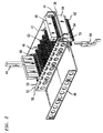
- FIG. 2 an illustration of the present invention mounting bracket 12 is shown from the rear.
- FIG. 2 illustrates that the mounting bracket 12 is comprised of two separate pieces, a front receptacle piece 46 and a rear bracket base 48.
- the rear base 48 is coupled longitudinally along a side edge to the front receptacle piece 46 by means of a hinge mechanism 50.
- the hinge mechanism 50 comprises a series of interleaved edges 52, 53 which edges are curled in such a manner so as to define alternating cylindrical hollows 54 within.
- the hollows are adapted to receive a cylindrical pin 56 or like member in order to align the curled edges 52, 53 and join the two pieces.
- the front receptacle 46 (or base 48) is then capable of rotating on the hinge 50 in varying degrees from a fully open or closed position.
- a closure 58 (shown in FIG. 1) may be included so as to secure the front piece 46 into place when closed.
- FIG. 1 utilizes a hinge mechanism to provide pivotal movement for the front of the bracket, it will be understood that other connecting schemes, for example a form of strap connection, may also be implemented with the bracket.
- the front receptacle piece may also be completely removable from the base (FIG. 1), wherein the front couples to the base by means of a snap-fit or force-fit connection.
- FIG. 2 shows the mounting bracket 12 to be fully stocked with connector modules 14.
- Sets of terminals 60,62 within the connector modules 14, for example, insulation displacement-type connector terminals face both to the front side 39 and rear 41 of the mounting bracket.
- the terminals 62 of the connector modules 14 are completely accessible from the rear when the mounting bracket is in an open position.
- a first connector module 64 is shown with a gas tube protector cartridge 66 mounted thereto, while a last connector module 68 is shown with a plurality of individual protectors 44 for covering single sets of connector terminals 60, 62.
- These protectors 44, 66 provide protection from excessive voltages or currents on the telephone wires caused by outside disturbances, such as lightning.
- the individual protectors 44 are utilized with the present invention ground bar 22 to provide a discharge path to the mounting bracket 12 and are coupled to the ground bar when inserted.
- the cartridge protectors 66 include an internal ground bus which provides a discharge path for all terminals on the connector module. This can be accomplished since the cartridge protector spans the entire width of receptacle slot.
- the ground bar of the cartridge protector as with the present invention ground bar 22, also couples to the posts 20 of the mounting bracket in order to complete a circuit path.
- the connector modules 14 are also adapted to receive the gas tube protector cartridges 66 and individual protectors 44 at the rear side 41 of the bracket. It will also be understood that the protector modules may include solid state (PTC), carbon-type or other like types of protection circuitry.
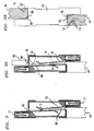
- FIG. 3 there is shown a cross-section of one preferred embodiment of a connector module 14.
- the connector module is shown with terminal caps 17 located on the front and rear side terminals 60, 62, respectively.
- a single terminal pair protector unit 44 is included on the rear side 41 of the connector module.
- the single unit protector 44 is inserted within the rear of the connector module 14, wherein a conductor 68 from the protector makes contact with both the front and rear terminals of the connector module. Insertion of the protector 44 causes a separation S between the front and back terminals 60, 62 of the protector module so that current is forced to flow through the protector 44.
- a cross section of the individual protector unit 44 is shown as the unit seats within the connector module 14.
- the individual protector 44 includes a cavity 72 which is adapted to receive and mate with the ground bar 22 to thereby establish an electrical discharge path for the protector.
- the ground bar 22 as shown is designed to fit over the connector module 14 and a positive seat 74 on the ground bar will indicate when an individual protector is fully inserted.
- Individual protectors 44 and corresponding ground bars 22 are shown installed in both the front and rear of the connector 14. This is done for illustration purposes to show the flexibility of the connector module system. Practical applications would normally require only that protection to be installed at one of these locations.
- FIG. 3A also illustrates an exclusionary feature included on the connector modules 14 to ensure proper polarity insertion of the protection modules 44, 66.
- a key 76 and slot 78 system is shown within the interior of an individual protector 44 which is to be installed on the rear of a connector module.
- Another corresponding key 86 and slot 88 is disposed at one end of an individual protector unit 44 which is to be installed in the front of a connector module 14.
- the exclusion feature ensures that current and voltage limiting protector units cannot be installed in the wrong orientation.
- a connector module having an individual protector 44 installed in the rear 41 of the module 14 and a test plug 84 installed in the front side 39 of the module.
- a tab 90 is included in a base portion the conductor 91 of the test plug 84 having sufficient width W1, to bias apart the terminals 60, 62 of the connector module when the test plug is inserted.
- a gap G of predetermined width is created between the front facing terminal 60 of the connector module and the conductor 68 of the individual protector module when the test plug 84 is inserted.
- the rear side terminal 62 (or cable termination side) remains coupled to the protector unit 44. This demonstrates the ability to test bi-directionally utilizing the test plug feature, while at the same time maintaining circuit protection on the rear or cable termination side of the connector block.
- the hinged mounting bracket and ground bar combination 10 provides a significant advantage over the prior art in that the rear of the connector modules 14 which make up the connector block 16 is easily accessible when the front receptacle piece 46 is in the open position.
- the mounting bracket is mounted at a telephone office or other premises by means of the bracket base.
- the base 48 as shown in FIG. 1 includes a series of apertures 92 in various dimensions comprising a universal mounting arrangement which enable the bracket to attach to a main distributing frame (MDF) on the horizontal or vertical side and to various cross-bars, frameworks and other mounting surfaces.
- MDF main distributing frame
- Cable terminations can then be made on the rear of the connector block 16, wherein the terminations are easily accessed, even after the bracket has been mounted, by swinging open the front portion 46 of the bracket to cause rotation about the hinge 50. Voltage and current protection in the form of the gas tube protectors 44, 66 used in conjunction with the ground bar 22 are also easily mountable in the rear of the connector block.
- the connector modules 14 are adapted to receive a test plug 84 at the front or rear of the of the modules to perform testing on each of the terminals 60, 62, both in an out of circuit, without removal of the circuit protection or terminations.
Landscapes
- Details Of Connecting Devices For Male And Female Coupling (AREA)
- Structure Of Telephone Exchanges (AREA)
Applications Claiming Priority (2)
| Application Number | Priority Date | Filing Date | Title |
|---|---|---|---|
| US08/442,900 US5595507A (en) | 1995-05-17 | 1995-05-17 | Mounting bracket and ground bar for a connector block |
| US442900 | 1995-05-17 |
Publications (2)
| Publication Number | Publication Date |
|---|---|
| EP0743713A2 true EP0743713A2 (de) | 1996-11-20 |
| EP0743713A3 EP0743713A3 (de) | 1997-12-10 |
Family
ID=23758599
Family Applications (1)
| Application Number | Title | Priority Date | Filing Date |
|---|---|---|---|
| EP96303418A Withdrawn EP0743713A3 (de) | 1995-05-17 | 1996-05-15 | Haltevorrichtung und Masseschiene für einen Verbindungsblock |
Country Status (9)
| Country | Link |
|---|---|
| US (1) | US5595507A (de) |
| EP (1) | EP0743713A3 (de) |
| JP (1) | JPH0922756A (de) |
| KR (1) | KR960043349A (de) |
| CN (1) | CN1148283A (de) |
| BR (1) | BR9602288A (de) |
| CA (1) | CA2175956A1 (de) |
| PL (1) | PL314283A1 (de) |
| ZA (1) | ZA963722B (de) |
Cited By (3)
| Publication number | Priority date | Publication date | Assignee | Title |
|---|---|---|---|---|
| WO1999036987A1 (es) * | 1998-01-15 | 1999-07-22 | Oberon Electronica, S.A. | Regleta telefonica |
| CN102804521A (zh) * | 2009-06-15 | 2012-11-28 | 3M创新有限公司 | 用于电信模块的接线条及安装方法 |
| EP2979326B1 (de) * | 2013-03-27 | 2016-11-23 | Molex Heavy Duty Connector Group S.R.L. | Tragrahmen für modulare steckverbinder |
Families Citing this family (70)
| Publication number | Priority date | Publication date | Assignee | Title |
|---|---|---|---|---|
| DE19710000C1 (de) * | 1997-03-12 | 1998-04-09 | Loh Kg Rittal Werk | Vorrichtung zum Befestigen von einer Reihe Anschlußleisten |
| US5989062A (en) * | 1997-07-31 | 1999-11-23 | Lucent Technologies Inc. | Reversible receptacle for mounting connectors |
| US5989063A (en) * | 1998-03-30 | 1999-11-23 | Lucent Technologies Inc. | Splice chamber and connector assembly for a building entrance protector |
| US6530805B1 (en) * | 1998-07-20 | 2003-03-11 | International Business Machines Corporation | Contact pin holder assembly |
| US6093041A (en) * | 1998-10-30 | 2000-07-25 | Lucent Technologies Inc. | Connector block with internal power bus |
| US6196869B1 (en) | 1998-10-30 | 2001-03-06 | Lucent Technologies Inc. | Mounting bracket and power bus for a connector block |
| US6166894A (en) * | 1999-03-15 | 2000-12-26 | Lucent Technologies Inc. | PCB based protector cartridge |
| US6761312B2 (en) * | 1999-07-30 | 2004-07-13 | Salamander Technologies, Inc. | System and method for tracking victims of a mass casualty incident |
| DE20104606U1 (de) * | 2001-03-16 | 2001-05-31 | 3M Innovative Properties Co., St. Paul, Minn. | Montagewanne für Anschlussmodule der Schneidklemmtechnik |
| US6658373B2 (en) | 2001-05-11 | 2003-12-02 | Field Diagnostic Services, Inc. | Apparatus and method for detecting faults and providing diagnostics in vapor compression cycle equipment |
| DE20203912U1 (de) * | 2002-03-11 | 2003-07-17 | 3M Innovative Properties Co., St. Paul, Minn. | Anschlußmodul der Telekommunikationstechnik und Kombination mit einem Anschlußmodul |
| US6814631B2 (en) | 2002-04-02 | 2004-11-09 | Marconi Intellectual Property (Ringfence) Inc. | Electrical terminal for surge protection cartridge |
| US6556411B1 (en) | 2002-04-02 | 2003-04-29 | Marconi Communications, Inc. | Purge protection cartridge with three-way attachment clip |
| US20040080954A1 (en) * | 2002-06-10 | 2004-04-29 | Eisenbruan Kenneth D. | Track mount |
| DE20217273U1 (de) * | 2002-11-09 | 2003-01-16 | HARTING Electric GmbH & Co. KG, 32339 Espelkamp | Befestigungsvorrichtung für Steckverbinder |
| BE1015731A3 (nl) * | 2003-10-23 | 2005-07-05 | Niko Nv | Inrichting voor het verbinden van elektrische componenten. |
| ES2333012T3 (es) * | 2004-03-18 | 2010-02-16 | 3M Innovative Properties Company | Circuito y metodo para proporcionar acceso a una sistema de ensayo y/o supervision. |
| US7303446B2 (en) * | 2005-05-18 | 2007-12-04 | 3M Innovative Proprties Company | Frame assembly |
| US20060264090A1 (en) * | 2005-05-18 | 2006-11-23 | Dower William V | Electrical connector assembly and method of forming the same |
| CN100394646C (zh) * | 2005-08-19 | 2008-06-11 | 力晶半导体股份有限公司 | 接地线板与应用此接地线板的活动式接地线汇流装置 |
| US8139761B2 (en) * | 2005-12-28 | 2012-03-20 | Corning Cable Systems Llc | Network interface device, apparatus, and methods |
| US11294135B2 (en) | 2008-08-29 | 2022-04-05 | Corning Optical Communications LLC | High density and bandwidth fiber optic apparatuses and related equipment and methods |
| US8452148B2 (en) | 2008-08-29 | 2013-05-28 | Corning Cable Systems Llc | Independently translatable modules and fiber optic equipment trays in fiber optic equipment |
| DE102008047375A1 (de) * | 2008-09-15 | 2010-04-15 | Cobi Net Fernmelde- Und Datennetzkomponenten Gmbh | Montagewanne |
| ATE534049T1 (de) | 2009-02-24 | 2011-12-15 | Ccs Technology Inc | Haltevorrichtung für ein kabel oder eine anordnung zur verwendung mit einem kabel |
| US20100220967A1 (en) * | 2009-02-27 | 2010-09-02 | Cooke Terry L | Hinged Fiber Optic Module Housing and Module |
| US8699838B2 (en) | 2009-05-14 | 2014-04-15 | Ccs Technology, Inc. | Fiber optic furcation module |
| US9075216B2 (en) | 2009-05-21 | 2015-07-07 | Corning Cable Systems Llc | Fiber optic housings configured to accommodate fiber optic modules/cassettes and fiber optic panels, and related components and methods |
| US8538226B2 (en) | 2009-05-21 | 2013-09-17 | Corning Cable Systems Llc | Fiber optic equipment guides and rails configured with stopping position(s), and related equipment and methods |
| CN102804520A (zh) * | 2009-06-15 | 2012-11-28 | 3M创新有限公司 | 用于电信模块的接线条的连接和切换接触元件 |
| GB0910199D0 (en) * | 2009-06-15 | 2009-07-29 | 3M Innovative Properties Co | Symmetrical termination strip for a telecommunications moduel |
| WO2010148336A1 (en) | 2009-06-19 | 2010-12-23 | Corning Cable Systems Llc | High density and bandwidth fiber optic apparatuses and related equipment and methods |
| US8712206B2 (en) | 2009-06-19 | 2014-04-29 | Corning Cable Systems Llc | High-density fiber optic modules and module housings and related equipment |
| AU2010263046B2 (en) | 2009-06-19 | 2015-07-23 | Corning Cable Systems Llc | High fiber optic cable packing density apparatus |
| US8625950B2 (en) | 2009-12-18 | 2014-01-07 | Corning Cable Systems Llc | Rotary locking apparatus for fiber optic equipment trays and related methods |
| US8992099B2 (en) | 2010-02-04 | 2015-03-31 | Corning Cable Systems Llc | Optical interface cards, assemblies, and related methods, suited for installation and use in antenna system equipment |
| US8913866B2 (en) | 2010-03-26 | 2014-12-16 | Corning Cable Systems Llc | Movable adapter panel |
| AU2011265751B2 (en) | 2010-04-16 | 2015-09-10 | Corning Optical Communications LLC | Sealing and strain relief device for data cables |
| EP2381284B1 (de) | 2010-04-23 | 2014-12-31 | CCS Technology Inc. | Glasfaserverteilungsvorrichtung für Unterboden |
| US8660397B2 (en) | 2010-04-30 | 2014-02-25 | Corning Cable Systems Llc | Multi-layer module |
| US9075217B2 (en) | 2010-04-30 | 2015-07-07 | Corning Cable Systems Llc | Apparatuses and related components and methods for expanding capacity of fiber optic housings |
| US9632270B2 (en) | 2010-04-30 | 2017-04-25 | Corning Optical Communications LLC | Fiber optic housings configured for tool-less assembly, and related components and methods |
| US8879881B2 (en) | 2010-04-30 | 2014-11-04 | Corning Cable Systems Llc | Rotatable routing guide and assembly |
| US8705926B2 (en) | 2010-04-30 | 2014-04-22 | Corning Optical Communications LLC | Fiber optic housings having a removable top, and related components and methods |
| US9519118B2 (en) | 2010-04-30 | 2016-12-13 | Corning Optical Communications LLC | Removable fiber management sections for fiber optic housings, and related components and methods |
| US9720195B2 (en) | 2010-04-30 | 2017-08-01 | Corning Optical Communications LLC | Apparatuses and related components and methods for attachment and release of fiber optic housings to and from an equipment rack |
| US8718436B2 (en) | 2010-08-30 | 2014-05-06 | Corning Cable Systems Llc | Methods, apparatuses for providing secure fiber optic connections |
| US9279951B2 (en) | 2010-10-27 | 2016-03-08 | Corning Cable Systems Llc | Fiber optic module for limited space applications having a partially sealed module sub-assembly |
| US8662760B2 (en) | 2010-10-29 | 2014-03-04 | Corning Cable Systems Llc | Fiber optic connector employing optical fiber guide member |
| WO2012074982A1 (en) | 2010-11-30 | 2012-06-07 | Corning Cable Systems Llc | Fiber device holder and strain relief device |
| WO2012106510A2 (en) | 2011-02-02 | 2012-08-09 | Corning Cable Systems Llc | Dense fiber optic connector assemblies and related connectors and cables suitable for establishing optical connections for optical backplanes in equipment racks |
| US9008485B2 (en) | 2011-05-09 | 2015-04-14 | Corning Cable Systems Llc | Attachment mechanisms employed to attach a rear housing section to a fiber optic housing, and related assemblies and methods |
| EP2726928A1 (de) | 2011-06-30 | 2014-05-07 | Corning Cable Systems LLC | Glasfasergeräteanordnungen ohne u-breitenformatige gehäuse und zugehörige verfahren |
| US8953924B2 (en) | 2011-09-02 | 2015-02-10 | Corning Cable Systems Llc | Removable strain relief brackets for securing fiber optic cables and/or optical fibers to fiber optic equipment, and related assemblies and methods |
| US9038832B2 (en) | 2011-11-30 | 2015-05-26 | Corning Cable Systems Llc | Adapter panel support assembly |
| US9250409B2 (en) | 2012-07-02 | 2016-02-02 | Corning Cable Systems Llc | Fiber-optic-module trays and drawers for fiber-optic equipment |
| US9042702B2 (en) | 2012-09-18 | 2015-05-26 | Corning Cable Systems Llc | Platforms and systems for fiber optic cable attachment |
| EP2725397B1 (de) | 2012-10-26 | 2015-07-29 | CCS Technology, Inc. | Glasfaserverwaltungseinheit und Glasfaserverteilungsvorrichtung |
| US8905766B2 (en) * | 2013-01-02 | 2014-12-09 | La Her | Grounding system for terminal block |
| US8985862B2 (en) | 2013-02-28 | 2015-03-24 | Corning Cable Systems Llc | High-density multi-fiber adapter housings |
| EP2854239B1 (de) * | 2013-09-25 | 2019-11-13 | Virginia Panel Corporation | Schnelles Datenmodul für Verbindungsvorrichtung mit hoher Lebensdauer |
| US9257788B1 (en) * | 2015-01-23 | 2016-02-09 | Oracle International Corporation | Connector retention and alignment assembly for use in computer and data storage mounting racks |
| DE102016213251A1 (de) * | 2016-07-20 | 2018-01-25 | Harting Electric Gmbh & Co. Kg | Halterahmenanordnung mit Grundrahmen und Fixierelement und Bestückungsverfahren |
| DE102017108430B4 (de) * | 2017-04-20 | 2021-09-30 | Harting Electric Gmbh & Co. Kg | Halterahmen für einen schweren Steckverbinder sowie System |
| DE102017108433B4 (de) | 2017-04-20 | 2021-09-30 | Harting Electric Gmbh & Co. Kg | Halterahmen für einen Steckverbinder und Verfahren zur Bestückung |
| DE102017108432A1 (de) | 2017-04-20 | 2018-10-25 | Harting Electric Gmbh & Co. Kg | Halterahmen für einen Steckverbinder und Verfahren zur Bestückung |
| DE102018103667B3 (de) * | 2018-02-19 | 2019-03-21 | PSZ electronic GmbH | Verbindungsvorrichtung zur Übertragung elektrischer Energie |
| FR3079358B1 (fr) * | 2018-03-23 | 2020-12-25 | Schneider Electric Ind Sas | Equipement electrique et procede de mise a la terre pour un tel equipement |
| CN110459899B (zh) * | 2019-09-05 | 2024-12-13 | 北京华电瑞通电力工程技术有限公司 | 一种手车柜用连接器 |
| DE102020107725B3 (de) * | 2020-03-20 | 2021-05-27 | Harting Electric Gmbh & Co. Kg | Geschirmtes Steckverbindermodul |
Family Cites Families (9)
| Publication number | Priority date | Publication date | Assignee | Title |
|---|---|---|---|---|
| BE794021A (fr) * | 1972-01-17 | 1973-05-02 | Western Electric Co | Bloc de connection de fils perfectionne |
| DE2725551C2 (de) * | 1977-06-07 | 1983-11-17 | Krone Gmbh, 1000 Berlin | Elektrischer Klemmverbinder |
| DE2804478C2 (de) * | 1978-01-31 | 1982-11-25 | Krone Gmbh, 1000 Berlin | Elektrischer Klemmverbinder zur löt-, schraub- und abisolierfreien Herstellung eines Kontaktes an einem feststehenden Anschlußelement, insbesondere für die Fernmeldelinientechnik |
| DE2811812C2 (de) * | 1978-03-16 | 1984-04-12 | Krone Gmbh, 1000 Berlin | Kabelendeinrichtung der Fernmeldelinientechnik |
| AR248462A1 (es) * | 1991-03-05 | 1995-08-18 | Quante Ag | Perfil portante con seccion transversal en forma de u para regletas de conexion y/o de seccionamiento de hilos de cable en disposiciones electricas. |
| US5281163A (en) * | 1991-09-23 | 1994-01-25 | Minnesota Mining And Manufacturing Company | Cross connect system for telecommunications systems |
| US5341269A (en) * | 1992-07-31 | 1994-08-23 | Illinois Tool Works Inc. | Voltage protector and grounding bar arrangement for terminal block |
| US5342209A (en) * | 1993-06-28 | 1994-08-30 | Porta Systems Corp. | Connector strip assembly with ground connection |
| DE4325952C2 (de) * | 1993-07-27 | 1997-02-13 | Krone Ag | Anschlußleiste für hohe Übertragungsraten in der Telekommunikations- und Datentechnik |
-
1995
- 1995-05-17 US US08/442,900 patent/US5595507A/en not_active Expired - Lifetime
-
1996
- 1996-05-07 CA CA002175956A patent/CA2175956A1/en not_active Abandoned
- 1996-05-10 ZA ZA963722A patent/ZA963722B/xx unknown
- 1996-05-15 EP EP96303418A patent/EP0743713A3/de not_active Withdrawn
- 1996-05-16 BR BR9602288A patent/BR9602288A/pt not_active Application Discontinuation
- 1996-05-16 KR KR1019960016416A patent/KR960043349A/ko not_active Abandoned
- 1996-05-16 JP JP8120729A patent/JPH0922756A/ja not_active Withdrawn
- 1996-05-16 PL PL96314283A patent/PL314283A1/xx unknown
- 1996-05-16 CN CN96105864A patent/CN1148283A/zh active Pending
Cited By (4)
| Publication number | Priority date | Publication date | Assignee | Title |
|---|---|---|---|---|
| WO1999036987A1 (es) * | 1998-01-15 | 1999-07-22 | Oberon Electronica, S.A. | Regleta telefonica |
| ES2141034A1 (es) * | 1998-01-15 | 2000-03-01 | Oberon Electronica S A | Regleta telefonica. |
| CN102804521A (zh) * | 2009-06-15 | 2012-11-28 | 3M创新有限公司 | 用于电信模块的接线条及安装方法 |
| EP2979326B1 (de) * | 2013-03-27 | 2016-11-23 | Molex Heavy Duty Connector Group S.R.L. | Tragrahmen für modulare steckverbinder |
Also Published As
| Publication number | Publication date |
|---|---|
| JPH0922756A (ja) | 1997-01-21 |
| PL314283A1 (en) | 1996-11-25 |
| CN1148283A (zh) | 1997-04-23 |
| EP0743713A3 (de) | 1997-12-10 |
| KR960043349A (ko) | 1996-12-23 |
| ZA963722B (en) | 1997-07-31 |
| CA2175956A1 (en) | 1996-11-18 |
| US5595507A (en) | 1997-01-21 |
| BR9602288A (pt) | 1998-01-13 |
Similar Documents
| Publication | Publication Date | Title |
|---|---|---|
| US5595507A (en) | Mounting bracket and ground bar for a connector block | |
| US5816854A (en) | Mounting bracket for connector block | |
| US5647760A (en) | Insulation displacement contact including retention means | |
| US4150867A (en) | Pre-wired terminal connecting block | |
| US5627721A (en) | Protector cartridge for modular connector blocks | |
| US5086368A (en) | Connector bank with voltage surge protection | |
| US5416837A (en) | Telephone network interface enclosure | |
| US5479505A (en) | Telephone network enclosure containing protected termination device | |
| US5548641A (en) | Protected telephone network termination module | |
| EP0487893B1 (de) | Modularer Abzweig-Steckverbinder | |
| US5412715A (en) | Apparatus and method for connecting telephone switching devices | |
| US5567173A (en) | Electrical connector | |
| US5622516A (en) | Insulation displacement terminal with two-wire insertion capability | |
| US6196869B1 (en) | Mounting bracket and power bus for a connector block | |
| HK35092A (en) | Connection block for cable cores, particularly those of telephone cables | |
| US5643014A (en) | Mounting of protectors in connector blocks | |
| US5805404A (en) | Common insulating housing for elements of varying terminals | |
| GB2323482A (en) | Electrical terminal structure for terminal strip with surge arrestor | |
| HU218951B (hu) | Elosztóegység távközlési és adatátviteli rendszerekhez, valamint ehhez való szerelőkengyel és kábelvezető elrendezés | |
| USRE31714E (en) | Pre-wired terminal connecting block | |
| US6093041A (en) | Connector block with internal power bus | |
| CA1139413A (en) | Pre-wired terminal connecting block | |
| US7323647B1 (en) | Modular device having separate connection and plug-actuated testing compartments | |
| WO1997023021A1 (en) | Test port jack for network interface device | |
| JPS60219889A (ja) | 電話分配フレーム接続装置 |
Legal Events
| Date | Code | Title | Description |
|---|---|---|---|
| PUAI | Public reference made under article 153(3) epc to a published international application that has entered the european phase |
Free format text: ORIGINAL CODE: 0009012 |
|
| AK | Designated contracting states |
Kind code of ref document: A2 Designated state(s): DE FR GB IT NL SE |
|
| PUAL | Search report despatched |
Free format text: ORIGINAL CODE: 0009013 |
|
| AK | Designated contracting states |
Kind code of ref document: A3 Designated state(s): DE FR GB IT NL SE |
|
| STAA | Information on the status of an ep patent application or granted ep patent |
Free format text: STATUS: THE APPLICATION IS DEEMED TO BE WITHDRAWN |
|
| 18D | Application deemed to be withdrawn |
Effective date: 19980611 |