EP0743715A2 - Einführungskraftfreier elektrischer Verbinder für Flachkabel - Google Patents
Einführungskraftfreier elektrischer Verbinder für Flachkabel Download PDFInfo
- Publication number
- EP0743715A2 EP0743715A2 EP96107185A EP96107185A EP0743715A2 EP 0743715 A2 EP0743715 A2 EP 0743715A2 EP 96107185 A EP96107185 A EP 96107185A EP 96107185 A EP96107185 A EP 96107185A EP 0743715 A2 EP0743715 A2 EP 0743715A2
- Authority
- EP
- European Patent Office
- Prior art keywords
- housing
- pressure plate
- terminals
- flat cable
- electrical connector
- Prior art date
- Legal status (The legal status is an assumption and is not a legal conclusion. Google has not performed a legal analysis and makes no representation as to the accuracy of the status listed.)
- Granted
Links
- 238000003780 insertion Methods 0.000 title claims abstract description 18
- 230000037431 insertion Effects 0.000 title claims abstract description 18
- 239000003989 dielectric material Substances 0.000 description 2
- 230000005540 biological transmission Effects 0.000 description 1
- 239000004020 conductor Substances 0.000 description 1
- 239000000463 material Substances 0.000 description 1
- 239000007769 metal material Substances 0.000 description 1
- 238000005476 soldering Methods 0.000 description 1
Images





Classifications
-
- H—ELECTRICITY
- H01—ELECTRIC ELEMENTS
- H01R—ELECTRICALLY-CONDUCTIVE CONNECTIONS; STRUCTURAL ASSOCIATIONS OF A PLURALITY OF MUTUALLY-INSULATED ELECTRICAL CONNECTING ELEMENTS; COUPLING DEVICES; CURRENT COLLECTORS
- H01R12/00—Structural associations of a plurality of mutually-insulated electrical connecting elements, specially adapted for printed circuits, e.g. printed circuit boards [PCB], flat or ribbon cables, or like generally planar structures, e.g. terminal strips, terminal blocks; Coupling devices specially adapted for printed circuits, flat or ribbon cables, or like generally planar structures; Terminals specially adapted for contact with, or insertion into, printed circuits, flat or ribbon cables, or like generally planar structures
- H01R12/70—Coupling devices
- H01R12/77—Coupling devices for flexible printed circuits, flat or ribbon cables or like structures
- H01R12/79—Coupling devices for flexible printed circuits, flat or ribbon cables or like structures connecting to rigid printed circuits or like structures
-
- H—ELECTRICITY
- H01—ELECTRIC ELEMENTS
- H01R—ELECTRICALLY-CONDUCTIVE CONNECTIONS; STRUCTURAL ASSOCIATIONS OF A PLURALITY OF MUTUALLY-INSULATED ELECTRICAL CONNECTING ELEMENTS; COUPLING DEVICES; CURRENT COLLECTORS
- H01R12/00—Structural associations of a plurality of mutually-insulated electrical connecting elements, specially adapted for printed circuits, e.g. printed circuit boards [PCB], flat or ribbon cables, or like generally planar structures, e.g. terminal strips, terminal blocks; Coupling devices specially adapted for printed circuits, flat or ribbon cables, or like generally planar structures; Terminals specially adapted for contact with, or insertion into, printed circuits, flat or ribbon cables, or like generally planar structures
- H01R12/50—Fixed connections
- H01R12/51—Fixed connections for rigid printed circuits or like structures
- H01R12/55—Fixed connections for rigid printed circuits or like structures characterised by the terminals
- H01R12/57—Fixed connections for rigid printed circuits or like structures characterised by the terminals surface mounting terminals
-
- H—ELECTRICITY
- H01—ELECTRIC ELEMENTS
- H01R—ELECTRICALLY-CONDUCTIVE CONNECTIONS; STRUCTURAL ASSOCIATIONS OF A PLURALITY OF MUTUALLY-INSULATED ELECTRICAL CONNECTING ELEMENTS; COUPLING DEVICES; CURRENT COLLECTORS
- H01R12/00—Structural associations of a plurality of mutually-insulated electrical connecting elements, specially adapted for printed circuits, e.g. printed circuit boards [PCB], flat or ribbon cables, or like generally planar structures, e.g. terminal strips, terminal blocks; Coupling devices specially adapted for printed circuits, flat or ribbon cables, or like generally planar structures; Terminals specially adapted for contact with, or insertion into, printed circuits, flat or ribbon cables, or like generally planar structures
- H01R12/70—Coupling devices
- H01R12/82—Coupling devices connected with low or zero insertion force
- H01R12/85—Coupling devices connected with low or zero insertion force contact pressure producing means, contacts activated after insertion of printed circuits or like structures
- H01R12/88—Coupling devices connected with low or zero insertion force contact pressure producing means, contacts activated after insertion of printed circuits or like structures acting manually by rotating or pivoting connector housing parts
Definitions
- This invention generally relates to the art of electrical connectors and, particularly, to an electrical connector for terminating a flat cable, such as a flat flexible cable, without requiring any insertion force.
- the actuators have been designed to be pushed in and pulled out of the connector housings. Such designs require the application of insertion forces to the flat cables. In addition, such designs have inevitably resulted in an increase in the overall size of the connectors.
- actuators which are pivotable between first, open positions allowing free insertion of the cables into the connector housings, and second, closed positions for clamping the flat cables against the terminals.
- lock means are provided to hold the actuators in locked condition relative to the connector housing.
- the present invention is directed to a new and improved zero insertion force electrical connector for flat cables of the character described above, wherein the actuator is pivotally mounted on the connector housing by means of a floating-pivot means and allows for increased linear or translational movement of the actuator in pushing the cable into the connector.
- An object, therefore, of the invention is to provide a new and improved zero insertion force electrical connector for flat electrical cables, of the character described.
- the zero insertion force electrical connector includes a dielectric housing mounting a plurality of terminals in a generally parallel array.
- the housing has opposite sides and a front end with an opening between the sides for receiving an end of the flat cable in engagement with contact portions of the terminals.
- An actuator in the form of a pressure plate is pivotally mounted relative to the housing for floating movement between a first position allowing free insertion of the flat cable into the opening, and a second position biasing the cable against the terminals.
- the actuator or pressure plate has an extension on its rearward end for movement beneath an overhanging shelf means on the housing.
- a forwardly facing cam surface is provided on the pressure plate for abutting a rearwardly facing cam surface on the housing as the pressure plate is rotated about a moving pivot from its first position to its second position causing the extension of the pressure plate to advance beneath the overhanging shelf means on the housing, thereby sandwiching the end of the flat cable between the contact portions of the terminals and the pressure plate.
- each of the terminals is bifurcated to define a contact branch and a support branch between which the flat cable is insertable.
- the support branches of the parallel array of terminals form the overhanging shelf means on the housing.
- the cam surfaces have cam profiles to allow substantial pivoting movement of the pressure plate relative to the housing followed by substantial translational movement of the pressure plate relative to the housing.
- Figure 1 shows an electrical connector for flat electrical cables according to the present invention.
- the connector includes a housing, generally designated 1, mounting a plurality of terminals, generally designated 2, and an actuator or pressure plate, generally designated 3.
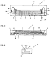
- Figures 2-4 show further details of housing 1
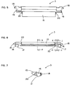
- Figures 5-10 show details of the actuator or pressure plate 3.
- Housing 1 is unitarily molded of dielectric material such as plastic or the like.
- the housing includes a bottom plate 5 having a plurality of slots 4 to accommodate terminals 3.
- the housing further includes opposite side walls 6 and a ceiling or top wall 7 which covers the top and approximately the rear one-half of the interior of the housing.
- Top wall 7 leaves an opening 8 in the front one-half of the housing and the front face of the housing for receiving the flat cable.
- each side wall 6 has a counter cam surface 9 facing in a rearward direction generally toward top wall 7. The counter cam surface cooperates with a cam surface on pressure plate 3 for guiding the pressure plate during its rotational and translational movements, as described hereinafter.
- each terminal 2 is stamped and formed of sheet metal material and in a generally bifurcated configuration to define a relatively long, lower contact branch 11 and a relatively short, upper support branch 10.
- the upper support branch includes a triangular barb 12 that bites into the plastic material of the housing to establish an interference fit therewith and, thereby, fix the terminal in the housing.
- Lower contact branch 11 of each terminal 2 is vertically flexible and includes an upwardly projecting contact portion 13 at its forward distal end and an L-shaped tail 14 at its rear end. Tail 14 is adapted for soldering to a circuit trace on a printed circuit board (not shown), and the bottom of tail 14 is flush with the lower surface of the wall 5 of the housing.
- the terminals are mounted in a generally parallel array transversely or side-to-side of the housing.
- the actuator or pressure plate 3 is unitarily molded of dielectric material such as plastic or the like.
- the pressure plate includes a major transverse flat plate 15 large enough to cover the opening or space 8 at the top front of housing 1.
- a pair of flanges 16 are integrally formed with opposite sides of the transverse flat plate 15.
- Each flange 16 is generally triangular and has a forwardly facing cam surface 17.
- Cam surfaces 17 on opposite flanges 16 of pressure plate 3 confront counter cam surfaces 9 on housing 1.
- Each flange 6 of pressure plate 3 has a laterally outwardly extending projection 18 on its outer surface.
- Each lateral projection 18 is movably fitted in an L-shaped slot 19 (Fig. 2) on the inner surface of a respective one of the side walls 6 of housing 1.
- the transverse flat plate 15 of the pressure plate has lateral projections 20 at its opposite sides and which extend beneath inwardly-projecting lateral extensions 21 (Fig. 3) inside opposite side walls 6 of housing 1.
- counter cam surface 9 on housing 1 includes a vertically linear cam section 22, a slanted cam section 23 and a curved cam section 24 consecutively or seriatim from the top to the bottom of cam surface 9.
- Cam surface 17 on pressure plate 3 includes a curved cam section 25, an angled cam section 26 and a vertically linear cam section 27 as viewed from bottom to top of cam surface 17.
- a forward extension 15a of transverse flat plate 15 of pressure plate 3 advances into housing 1 such that the upper surface of forward extension 15a engages and moves under a comb-like lower bearing surface or shelf 28 defined by the underside of support branches 10 of the generally parallel array of terminals 2.
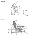
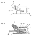
- FIGs 11 and subsequent drawings show the manner in which pressure plate 3 moves in a floating action (i.e. like a floating pivot) with respect to housing 1.
- pressure plate 3 is shown in its fully opened position in which a flat flexible cable 29 can be inserted into the housing. It should be noted that the flat cable is inserted into the housing without requiring any insertion force. It can be seen in Figure 12 that the flat cable rests on top of contact portions 13 of flexible contact branches 11 of terminals 2.
- pressure plate 3 is rotated in the direction of arrows 30 until cam surfaces 17 on the pressure plate begins to abut the counter cam surfaces 9 on the housing, as shown in Figures 13, 14, 15 and 16.
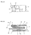
- Figures 21 and 22 show the final position of actuator or pressure plate 3 relative to housing 1.
- vertically linear cam section 27 of cam surface 17 of pressure plate 3 abuts vertically linear cam section 22 of cam surface 9 on housing 1, while forward extension 15a of the transverse plate 15 of pressure plate 3 is positioned fully under the shelf means formed by support branches 10 of terminals 2.
- flat cable 29 is sandwiched between the lower surface of forward extension 15a and contact portions 13 of contact branches 11 of terminals 2, with each exposed conductor on the underside of the flat cable contacting a contact portion 13 of a respective one of the terminals.
- Figure 23 is a schematic illustration to show a horizontal distance "L” between a final center of rotation “O” of pressure plate 3 and the point of pressure "P” in the final position of the pressure plate.
- pressure plate 3 is pushed forwardly while being rotated in a floating pivoting manner, as a counter action to housing 1 caused by the cooperation between cam surface 17 on the pressure plate and counter cam surface 9 on the housing.
- This provides an increased horizontal distance "L" (Fig. 23) from the final center of rotation to the pressure point, compared to prior art actuators that rotate about a fixed pivot.
- increased resistance is provided against the flat cable from slipping out of the connector when subjected to undesirable pulling forces which might tend to rotate pressure plate 3 toward its open position.
- pressure point "P” moves from the left-hand side of center of rotation "O” to the right-hand side as viewed in Figure 23 to form a type of toggle arrangement as the pressure plate rotates and translates toward its final position. Therefore, no latching mechanism is necessitated because pulling on the cable only tightens its clamped engagement.
- inward lateral extensions 21 of the side walls of housing 1 overhang the opposite longitudinal edges of flat cable 29. These overhanging extensions tend to absorb at least a part of any undesirable pulling force applied to the flat cable, thereby reducing transmission of the pulling force to pressure plate 3 in the opening direction of the pressure plate.
- pressure plate 3 In order to remove flat cable 29 from the electrical connector, pressure plate 3 is rotated in the direction of arrow 32 (Fig. 22) to cause a pulling force on the pressure plate in the direction of arrow 33. The pressure plate then can be rotated about its floating or moving pivot back to its fully open position as shown in Figures 11 and 12 to permit easy removal of the flat cable.
- housing 1 may be designed to have a horizontal extension on the inside thereof to provide a shelf means or bearing surface 28 rather than providing the bearing surface by means of support branches 10 of terminals 3.
- L-shaped tails 14 of terminals 2 may be replaced by pin-like tails which can be inserted into holes in a printed circuit board.
Landscapes
- Coupling Device And Connection With Printed Circuit (AREA)
Applications Claiming Priority (3)
| Application Number | Priority Date | Filing Date | Title |
|---|---|---|---|
| JP14409995 | 1995-05-18 | ||
| JP7144099A JP2824747B2 (ja) | 1995-05-18 | 1995-05-18 | 平型柔軟ケーブル用電気コネクタ |
| JP144099/95 | 1995-05-18 |
Publications (3)
| Publication Number | Publication Date |
|---|---|
| EP0743715A2 true EP0743715A2 (de) | 1996-11-20 |
| EP0743715A3 EP0743715A3 (de) | 1997-10-01 |
| EP0743715B1 EP0743715B1 (de) | 2000-12-27 |
Family
ID=15354179
Family Applications (1)
| Application Number | Title | Priority Date | Filing Date |
|---|---|---|---|
| EP96107185A Expired - Lifetime EP0743715B1 (de) | 1995-05-18 | 1996-05-07 | Einführungskraftfreier elektrischer Verbinder für Flachkabel |
Country Status (9)
| Country | Link |
|---|---|
| US (1) | US5695360A (de) |
| EP (1) | EP0743715B1 (de) |
| JP (1) | JP2824747B2 (de) |
| KR (1) | KR100212925B1 (de) |
| DE (1) | DE69611320T2 (de) |
| ES (1) | ES2154362T3 (de) |
| MY (1) | MY116520A (de) |
| SG (1) | SG66309A1 (de) |
| TW (1) | TW311763U (de) |
Cited By (10)
| Publication number | Priority date | Publication date | Assignee | Title |
|---|---|---|---|---|
| EP0855766A3 (de) * | 1997-01-23 | 1999-06-16 | Sumitomo Wiring Systems, Ltd. | Elektrischer Verbinder eines flachen elektrischen Leiters |
| EP0978904A1 (de) * | 1998-07-17 | 2000-02-09 | Molex Incorporated | Elektrischer Kleinprofilverbinder für Flachstromkreise |
| EP0989632A1 (de) * | 1998-09-25 | 2000-03-29 | Molex Incorporated | Elektrischer Verbinder für flache Schaltungseinheiten |
| EP0926778A3 (de) * | 1997-12-24 | 2001-05-09 | Japan Solderless Terminal Mfg Co Ltd | Verbinder für Leiterplatten |
| EP1235304A1 (de) * | 2001-02-22 | 2002-08-28 | Yazaki Corporation | Steckverbinder für ein Flachbandkabel |
| WO2003009425A1 (en) * | 2001-07-18 | 2003-01-30 | Molex Inc. | Electrical connector assembly for flat flexible circuitry |
| EP1244180A3 (de) * | 2001-03-23 | 2003-11-19 | Hirose Electric Co., Ltd. | Elektrischer Verbinder für Flachkabel und Herstellungsverfahren |
| WO2006031279A1 (en) * | 2004-07-06 | 2006-03-23 | Molex Incorporated | Flat circuit connector with pivoted actuator |
| EP3038212A1 (de) * | 2014-12-22 | 2016-06-29 | Wago Verwaltungsgesellschaft mbH | Anschlussklemme |
| CN106410482A (zh) * | 2016-06-02 | 2017-02-15 | 浙江新富尔电子有限公司 | 一种立式掀盖连接器 |
Families Citing this family (27)
| Publication number | Priority date | Publication date | Assignee | Title |
|---|---|---|---|---|
| JP2841043B2 (ja) * | 1996-04-15 | 1998-12-24 | 日本航空電子工業株式会社 | コネクタ |
| JP3101951B2 (ja) * | 1997-01-24 | 2000-10-23 | 日本電気株式会社 | 低挿抜力コネクタ |
| JP3417252B2 (ja) * | 1997-05-13 | 2003-06-16 | 住友電装株式会社 | シート状導電路用コネクタ |
| JP3005497B2 (ja) | 1997-05-29 | 2000-01-31 | 東北日本電気株式会社 | フレキシブル基板用コネクタ |
| JP3430398B2 (ja) * | 1998-07-31 | 2003-07-28 | 日本航空電子工業株式会社 | ケーブル用コネクタ |
| TW417855U (en) * | 1999-06-08 | 2001-01-01 | Hon Hai Prec Ind Co Ltd | Electric connector |
| US6213802B1 (en) * | 1999-06-08 | 2001-04-10 | Hon Hai Precision Ind. Co., Ltd. | Electrical connector |
| TW430169U (en) * | 1999-09-09 | 2001-04-11 | Hon Hai Prec Ind Co Ltd | Electrical connector |
| US6203345B1 (en) * | 1999-11-09 | 2001-03-20 | Hon Hai Precision Ind. Co., Ltd. | Flexible circuit connector |
| JP3446136B2 (ja) | 2000-06-05 | 2003-09-16 | モレックス インコーポレーテッド | 電気コネクタ |
| TW493856U (en) * | 2001-05-04 | 2002-07-01 | Super Link Electronics Co Ltd | Flexible circuit board connector |
| US7336139B2 (en) * | 2002-03-18 | 2008-02-26 | Applied Micro Circuits Corporation | Flexible interconnect cable with grounded coplanar waveguide |
| US8847696B2 (en) * | 2002-03-18 | 2014-09-30 | Qualcomm Incorporated | Flexible interconnect cable having signal trace pairs and ground layer pairs disposed on opposite sides of a flexible dielectric |
| TW532663U (en) | 2002-06-20 | 2003-05-11 | Hon Hai Prec Ind Co Ltd | A connector assembly |
| JP2004235136A (ja) * | 2002-12-06 | 2004-08-19 | Yazaki Corp | コネクタ |
| TW582631U (en) * | 2003-06-27 | 2004-04-01 | Hon Hai Prec Ind Co Ltd | Electrical connector |
| TWM249255U (en) * | 2003-07-23 | 2004-11-01 | Hon Hai Prec Ind Co Ltd | Electrical connector |
| TWM250340U (en) * | 2003-08-01 | 2004-11-11 | Hon Hai Prec Ind Co Ltd | Electrical connector |
| CN2718819Y (zh) * | 2004-06-23 | 2005-08-17 | 富士康(昆山)电脑接插件有限公司 | 柔性印刷电路连接器 |
| JP4388879B2 (ja) * | 2004-10-26 | 2009-12-24 | 日本圧着端子製造株式会社 | コネクタ |
| TWM282346U (en) * | 2005-05-06 | 2005-12-01 | Hon Hai Prec Ind Co Ltd | Electrical connector |
| JP4692079B2 (ja) * | 2005-05-31 | 2011-06-01 | オムロン株式会社 | コネクタ |
| US20070054558A1 (en) * | 2005-09-03 | 2007-03-08 | Harlan Tod M | Connector with improved pulling portion |
| US7121874B1 (en) | 2005-09-26 | 2006-10-17 | Myoungsoo Jeon | Flexible printed circuit (FPC) edge connector |
| JP4731311B2 (ja) * | 2005-12-27 | 2011-07-20 | 第一電子工業株式会社 | カム構造及び該カム構造を使用するコネクタ |
| KR100790335B1 (ko) * | 2006-10-30 | 2008-01-02 | 한국단자공업 주식회사 | 이단 분리 결합용 커넥터 하우징 |
| JP6575898B2 (ja) * | 2015-06-26 | 2019-09-18 | パナソニックIpマネジメント株式会社 | コネクタ |
Family Cites Families (9)
| Publication number | Priority date | Publication date | Assignee | Title |
|---|---|---|---|---|
| JPS58126512A (ja) * | 1982-01-23 | 1983-07-28 | Asahi Optical Co Ltd | 大口径望遠レンズ |
| DE8626537U1 (de) * | 1986-10-03 | 1988-06-23 | Grote & Hartmann Gmbh & Co Kg, 5600 Wuppertal | Folienverbinder für gedruckte Schaltungen |
| JPS63274074A (ja) * | 1987-05-01 | 1988-11-11 | アンプ インコ−ポレ−テツド | 電気コンタクトアセンブリおよびその製造方法 |
| US4778403A (en) * | 1987-07-15 | 1988-10-18 | Elco Corporation | Zero insertion force connector |
| JPH088550Y2 (ja) * | 1988-01-14 | 1996-03-06 | アンプ インコーポレーテッド | フラットケーブル用コネクタ |
| JPH0724230B2 (ja) * | 1990-10-25 | 1995-03-15 | 京セラエルコ株式会社 | 無挿抜力コネクタ |
| TW233382B (de) * | 1993-04-02 | 1994-11-01 | Hirose Electric Co Ltd | |
| JP2820855B2 (ja) * | 1993-04-07 | 1998-11-05 | トーマス アンド ベッツ コーポレーション | コネクタ |
| JP2892945B2 (ja) * | 1994-08-05 | 1999-05-17 | ヒロセ電機株式会社 | フレキシブル基板用電気コネクタ |
-
1995
- 1995-05-18 JP JP7144099A patent/JP2824747B2/ja not_active Expired - Fee Related
-
1996
- 1996-03-25 TW TW086203032U patent/TW311763U/zh unknown
- 1996-03-28 US US08/623,269 patent/US5695360A/en not_active Expired - Lifetime
- 1996-05-07 DE DE69611320T patent/DE69611320T2/de not_active Expired - Fee Related
- 1996-05-07 ES ES96107185T patent/ES2154362T3/es not_active Expired - Lifetime
- 1996-05-07 EP EP96107185A patent/EP0743715B1/de not_active Expired - Lifetime
- 1996-05-14 MY MYPI96001814A patent/MY116520A/en unknown
- 1996-05-16 SG SG1996009813A patent/SG66309A1/en unknown
- 1996-05-17 KR KR1019960016601A patent/KR100212925B1/ko not_active Expired - Fee Related
Cited By (15)
| Publication number | Priority date | Publication date | Assignee | Title |
|---|---|---|---|---|
| EP0855766A3 (de) * | 1997-01-23 | 1999-06-16 | Sumitomo Wiring Systems, Ltd. | Elektrischer Verbinder eines flachen elektrischen Leiters |
| US6056571A (en) * | 1997-01-23 | 2000-05-02 | Sumitomo Hiring Systems, Ltd. | Electrical connector for flat electrical conductor |
| EP0926778A3 (de) * | 1997-12-24 | 2001-05-09 | Japan Solderless Terminal Mfg Co Ltd | Verbinder für Leiterplatten |
| EP0978904A1 (de) * | 1998-07-17 | 2000-02-09 | Molex Incorporated | Elektrischer Kleinprofilverbinder für Flachstromkreise |
| SG81288A1 (en) * | 1998-07-17 | 2001-06-19 | Molex Inc | Low profile electrical connector for flat circuits |
| EP0989632A1 (de) * | 1998-09-25 | 2000-03-29 | Molex Incorporated | Elektrischer Verbinder für flache Schaltungseinheiten |
| EP1235304A1 (de) * | 2001-02-22 | 2002-08-28 | Yazaki Corporation | Steckverbinder für ein Flachbandkabel |
| US6558187B2 (en) | 2001-02-22 | 2003-05-06 | Yazaki Corporation | Connector for flat circuit member |
| EP1244180A3 (de) * | 2001-03-23 | 2003-11-19 | Hirose Electric Co., Ltd. | Elektrischer Verbinder für Flachkabel und Herstellungsverfahren |
| US6711816B2 (en) | 2001-03-23 | 2004-03-30 | Hirose Electric Co., Ltd. | Method of manufacturing electrical connector for flat cable |
| WO2003009425A1 (en) * | 2001-07-18 | 2003-01-30 | Molex Inc. | Electrical connector assembly for flat flexible circuitry |
| WO2006031279A1 (en) * | 2004-07-06 | 2006-03-23 | Molex Incorporated | Flat circuit connector with pivoted actuator |
| US7553183B2 (en) | 2004-07-06 | 2009-06-30 | Molex Incorporated | Flat circuit connector with pivoted actuator |
| EP3038212A1 (de) * | 2014-12-22 | 2016-06-29 | Wago Verwaltungsgesellschaft mbH | Anschlussklemme |
| CN106410482A (zh) * | 2016-06-02 | 2017-02-15 | 浙江新富尔电子有限公司 | 一种立式掀盖连接器 |
Also Published As
| Publication number | Publication date |
|---|---|
| EP0743715A3 (de) | 1997-10-01 |
| SG66309A1 (en) | 1999-07-20 |
| ES2154362T3 (es) | 2001-04-01 |
| TW311763U (en) | 1997-07-21 |
| JP2824747B2 (ja) | 1998-11-18 |
| EP0743715B1 (de) | 2000-12-27 |
| DE69611320T2 (de) | 2001-06-13 |
| KR100212925B1 (ko) | 1999-08-02 |
| MY116520A (en) | 2004-02-28 |
| DE69611320D1 (de) | 2001-02-01 |
| US5695360A (en) | 1997-12-09 |
| KR960043348A (ko) | 1996-12-23 |
| JPH08321365A (ja) | 1996-12-03 |
Similar Documents
| Publication | Publication Date | Title |
|---|---|---|
| EP0743715B1 (de) | Einführungskraftfreier elektrischer Verbinder für Flachkabel | |
| KR100675046B1 (ko) | 편평형 도체의 접속을 위한 전기 커넥터 | |
| US5695359A (en) | Zero insertion force electrical connector for flat cable | |
| KR950003111Y1 (ko) | 플랫 전기 케이블용 전기 커넥터 | |
| US4778403A (en) | Zero insertion force connector | |
| KR100373597B1 (ko) | 커넥터에 접속되어 있는 박판형 물체와 평행한 방향의접촉편에 결합된 회전식 액추에이터를 가지는 커넥터 | |
| EP0667651B1 (de) | Elektrischer Verbinder | |
| US6726497B2 (en) | Connector for flat flexible cable | |
| US6422896B2 (en) | Flat circuit member connector | |
| EP0561288B1 (de) | Leiterplatten-Klemmverbinder | |
| US4577920A (en) | Electrical assembly with cable guiding member | |
| US20020048999A1 (en) | Electrical connector | |
| US5895287A (en) | Flat cable connector | |
| US5934932A (en) | Electrical connector for flat cables | |
| US6997756B2 (en) | Connector terminal, a connector and a mounting method | |
| US6004156A (en) | Flat flexible cable connector | |
| US5921785A (en) | Electrical connector for flat cables | |
| US4444450A (en) | Flat transmission cable connector and housing therefor | |
| US6648659B2 (en) | Lever-type connector and a method for mounting a lever-type connector into a hole of a panel | |
| US7344399B2 (en) | Flat circuit connector | |
| US6196883B1 (en) | Connection spring for electrical connections | |
| EP1063728B1 (de) | Spannungsführender Steckanschluss | |
| EP0401938B1 (de) | Elektrischer Verbinder | |
| WO1998009345A1 (en) | Flexible circuit board connector | |
| US5632646A (en) | Electric connector for flexible flat cables |
Legal Events
| Date | Code | Title | Description |
|---|---|---|---|
| PUAI | Public reference made under article 153(3) epc to a published international application that has entered the european phase |
Free format text: ORIGINAL CODE: 0009012 |
|
| AK | Designated contracting states |
Kind code of ref document: A2 Designated state(s): DE ES FR GB IT |
|
| PUAL | Search report despatched |
Free format text: ORIGINAL CODE: 0009013 |
|
| AK | Designated contracting states |
Kind code of ref document: A3 Designated state(s): DE ES FR GB IT |
|
| 17P | Request for examination filed |
Effective date: 19980224 |
|
| GRAG | Despatch of communication of intention to grant |
Free format text: ORIGINAL CODE: EPIDOS AGRA |
|
| 17Q | First examination report despatched |
Effective date: 20000216 |
|
| GRAG | Despatch of communication of intention to grant |
Free format text: ORIGINAL CODE: EPIDOS AGRA |
|
| GRAH | Despatch of communication of intention to grant a patent |
Free format text: ORIGINAL CODE: EPIDOS IGRA |
|
| RIC1 | Information provided on ipc code assigned before grant |
Free format text: 7H 01R 12/16 A, 7H 01R 12/24 B |
|
| ITF | It: translation for a ep patent filed | ||
| GRAH | Despatch of communication of intention to grant a patent |
Free format text: ORIGINAL CODE: EPIDOS IGRA |
|
| GRAA | (expected) grant |
Free format text: ORIGINAL CODE: 0009210 |
|
| AK | Designated contracting states |
Kind code of ref document: B1 Designated state(s): DE ES FR GB IT |
|
| REF | Corresponds to: |
Ref document number: 69611320 Country of ref document: DE Date of ref document: 20010201 |
|
| ET | Fr: translation filed | ||
| REG | Reference to a national code |
Ref country code: ES Ref legal event code: FG2A Ref document number: 2154362 Country of ref document: ES Kind code of ref document: T3 |
|
| PGFP | Annual fee paid to national office [announced via postgrant information from national office to epo] |
Ref country code: GB Payment date: 20010404 Year of fee payment: 6 |
|
| PGFP | Annual fee paid to national office [announced via postgrant information from national office to epo] |
Ref country code: FR Payment date: 20010503 Year of fee payment: 6 |
|
| PGFP | Annual fee paid to national office [announced via postgrant information from national office to epo] |
Ref country code: ES Payment date: 20010517 Year of fee payment: 6 |
|
| PGFP | Annual fee paid to national office [announced via postgrant information from national office to epo] |
Ref country code: DE Payment date: 20010530 Year of fee payment: 6 |
|
| PLBE | No opposition filed within time limit |
Free format text: ORIGINAL CODE: 0009261 |
|
| STAA | Information on the status of an ep patent application or granted ep patent |
Free format text: STATUS: NO OPPOSITION FILED WITHIN TIME LIMIT |
|
| 26N | No opposition filed | ||
| REG | Reference to a national code |
Ref country code: GB Ref legal event code: IF02 |
|
| PG25 | Lapsed in a contracting state [announced via postgrant information from national office to epo] |
Ref country code: GB Free format text: LAPSE BECAUSE OF NON-PAYMENT OF DUE FEES Effective date: 20020507 |
|
| PG25 | Lapsed in a contracting state [announced via postgrant information from national office to epo] |
Ref country code: ES Free format text: LAPSE BECAUSE OF NON-PAYMENT OF DUE FEES Effective date: 20020508 |
|
| PG25 | Lapsed in a contracting state [announced via postgrant information from national office to epo] |
Ref country code: DE Free format text: LAPSE BECAUSE OF NON-PAYMENT OF DUE FEES Effective date: 20021203 |
|
| GBPC | Gb: european patent ceased through non-payment of renewal fee |
Effective date: 20020507 |
|
| PG25 | Lapsed in a contracting state [announced via postgrant information from national office to epo] |
Ref country code: FR Free format text: LAPSE BECAUSE OF NON-PAYMENT OF DUE FEES Effective date: 20030131 |
|
| REG | Reference to a national code |
Ref country code: FR Ref legal event code: ST |
|
| REG | Reference to a national code |
Ref country code: ES Ref legal event code: FD2A Effective date: 20030611 |
|
| PG25 | Lapsed in a contracting state [announced via postgrant information from national office to epo] |
Ref country code: IT Free format text: LAPSE BECAUSE OF NON-PAYMENT OF DUE FEES;WARNING: LAPSES OF ITALIAN PATENTS WITH EFFECTIVE DATE BEFORE 2007 MAY HAVE OCCURRED AT ANY TIME BEFORE 2007. THE CORRECT EFFECTIVE DATE MAY BE DIFFERENT FROM THE ONE RECORDED. Effective date: 20050507 |