EP0743720A2 - Dispositif à balais pour moteur électrique - Google Patents
Dispositif à balais pour moteur électrique Download PDFInfo
- Publication number
- EP0743720A2 EP0743720A2 EP96303357A EP96303357A EP0743720A2 EP 0743720 A2 EP0743720 A2 EP 0743720A2 EP 96303357 A EP96303357 A EP 96303357A EP 96303357 A EP96303357 A EP 96303357A EP 0743720 A2 EP0743720 A2 EP 0743720A2
- Authority
- EP
- European Patent Office
- Prior art keywords
- brush
- commutator
- arm
- brush body
- ridge
- Prior art date
- Legal status (The legal status is an assumption and is not a legal conclusion. Google has not performed a legal analysis and makes no representation as to the accuracy of the status listed.)
- Granted
Links
Images


Classifications
-
- H—ELECTRICITY
- H01—ELECTRIC ELEMENTS
- H01R—ELECTRICALLY-CONDUCTIVE CONNECTIONS; STRUCTURAL ASSOCIATIONS OF A PLURALITY OF MUTUALLY-INSULATED ELECTRICAL CONNECTING ELEMENTS; COUPLING DEVICES; CURRENT COLLECTORS
- H01R39/00—Rotary current collectors, distributors or interrupters
- H01R39/02—Details for dynamo electric machines
- H01R39/38—Brush holders
- H01R39/39—Brush holders wherein the brush is fixedly mounted in the holder
Definitions
- the present invention relates to a brush assembly for an electric motor, particularly but not exclusively, for miniature permanent magnet d.c. motors.
- One method adopted to reduce the generation of electrical noise was to provide the brush face with a concave shape so that the brush contacts the commutator at two points. It was thought that as the commutator rotates, the brush bounces on the commutator due to the commutator not being perfectly round and through the brush contacting the edges of segments of the commutator as it rotates. By providing two contact points, the contact between the brush and the commutator segments was likely to be maintained as the brush twists and bounces during operation. Indeed, a significant improvement was achieved over the older flat faced design, resulting in a quicker wearing in of the brushes on the commutator surface, providing a better sliding contact between the commutator and the brushes. It was thought that the flat faced brush, in effect, as it was bedding in, only contacted the commutator at a single point.
- Another method adopted requires vibration dampening material to be applied along the support arm to dampen the vibrations of the support arm to reduce the severity of the bouncing of the brush.
- the present invention provides a brush body for an elongate brush arm of a miniature electric motor, the brush body having an upper face arranged for fixing with the brush arm, a lower face arranged for making sliding contact with a commutator of the motor; first and second sides extending between the upper and lower faces; and first and second end faces extending between the upper and lower faces and between the sides, the brush body being adapted so that in use the sides are spaced in the axial direction and the end faces are spaced in the circumferential direction of the commutator characterised in that the lower face has a single ridge extending between the first and second end faces and offset towards the first side.
- the ridge extends substantially parallel to the upper face and the sides and substantially perpendicular to the end faces.
- the present invention provides a brush assembly for an electric motor, the brush assembly comprising a brush body for making sliding contact with a commutator, a brush holder and an elongate resiliently flexible electrically conductive brush arm supporting the brush body and electrically connecting the brush body to the brush holder characterised in that the brush body contacts the commutator at a single point which is laterally offset from a central plane of the brush body such that the resilient urgings of the brush arm urging the brush body into contact with the commutator creates a twist in the brush arm.
- the support arm and brush may be arranged so that the brush contacts the commutator at a single point along an edge of the brush face.
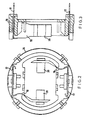
- the motor has a shaft 10 carrying a wound armature 11 and a commutator 12.
- a casing 13 has mounted therein two field magnets 14 and an end bearing 15 for supporting the shaft 10.
- a moulded plastics material end cap 16 provides a brush holder which supports two brush assemblies. Each assembly has a terminal part 17 connected to a resilient brush supporting arm or brush leaf 18. Brush 20 is supported by the free end of the brush leaf. The brush is urged in use into contact with the commutator 12 by the brush leaf 18.
- the terminals 17 and brush leaves are fixed together by a set of rivets 23.
- Other forms of fixing can be used, such as a clip fixing.
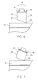
- the top of the brushes 20 are shaped to form a single castellation (see Figure 6) and are held in slots provided in and adjacent the free ends of the brush leaves 18 by fingers 19 formed along edges of the slots which grip and bite into the castellation to secure the brush in place.
- the brush assembly is similar to known leaf-type brush assemblies for miniature electric motors.
- the face of the brush which contacts the commutator is formed as a wedge shape or sloping surface to form a single contact ridge 25 with the commutator 12.
- the brush contacts the commutator at a single point which is offset from the centre of the brush so that due to the resilient urgings of the brush arm 18, the brush 20 tends to pivot axially of the commutator causing the brush arm to twist as indicated by arrow A. This twisting seems to strengthen the brush arm against bouncing movement radially of the commutator.
- the single contact point also allows the brush to bed in more quickly creating a good sliding contact surface between the commutator and the brush 20.
- the reduction in bouncing of the brush on the commutator reduces the creation of sparks between the brush and the commutator and the formation of a good sliding contact surface between the commutator and the brush reduces the level of noise, both electrical and mechanical, resulting in a quieter motor.
- the brush assembly is arranged to form a single contact point with the commutator 12 as before, but this is achieved using a standard square faced brush 20' fitted to a brush arm 18' which has been twisted, resulting in the brush 20' contacting the commutator at a single point along a single contact ridge 25'. Again, the urging of the brush leaf 18' places a twisting moment on the brush leaf to reduce its bouncing without increasing the brush contact pressure.
- a further embodiment provides for a particular shape of the brush as shown in Figure 8.
- the brush appears to have a vertically extending side face 26, i.e., a face which extends perpendicular to the motor axis when the motor is assembled. However, it does not extend perpendicular to the brush arm.
- the brush is shown in Figure 8 oriented with its axis vertical as it would appear in its free form when attached to the brush arm, i.e., before contact with the commutator.
- the brush 20 is shaped so that in use, side 26 of brush 20 will extend perpendicular to the motor axis. This is desired so that it forms a stable contact point with the commutator as the brush wears.
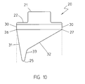
- the brush body 20 is formed with a mounting projection 21 on its upper surface 22, with a ridge 25 formed on the lower surface which contacts the commutator and with sides 26 and 27 extending between the ridge 25 and the upper surface.
- the ridge extends substantially parallel to the upper surface and to the sides 26 and 27. Both sides have a short vertical portion 30 adjacent the upper surface 22.
- the other side 27 is divided into three portions: a vertical portion 30 adjacent the upper face as already mentioned, an initial portion 33 adjacent the ridge 25 which extends at 55° to the vertical and a main portion 32, joining the other two portions, extending at 60° to the vertical.
- the 5° difference between the main portion 32 and the initial portion 33 of side 27 provides the ridge with slightly more material to slightly retard the initial wear of the brush as it beds in.
- Figure 9 illustrates a preferred configuration of the brush arm in which a damper 15 is fixed to the brush arm to absorb or reduce the vibrations generated in the brush arm during operation of the motor.
- the damper may be of any suitable material but is preferably a synthetic rubber based material attached to the brush arm by adhesive.
- a slot 14 extends longitudinally of the brush arm in a portion of the brush arm adjacent the brush holder 17.
- the provision of the slot 14 reduces the spring force of the brush arm in this area while increasing its flexibility.
- the spring force of the brush arm can be reduced while maintaining a wide base to the brush arm to prevent the brush arm moving laterally, allowing the brush to meander axially across the surface of the commutator. It also limits the bending of the brush arm to this portion of the brush arm. Bending of the brush arm is further limited to this portion by reinforcing ribs 13 formed along each side of the brush arm at the distal end thereof.
- Figure 10 illustrates a brush similar to the brush of Figure 8 except that the ridge 25 is more pronounced. This provides a longer running time with a smaller contact area, meaning that the point contact with the commutator is maintained to ensure a better bedding in of the brush and the commutator contact surface.
Landscapes
- Motor Or Generator Current Collectors (AREA)
- Motor Or Generator Frames (AREA)
Applications Claiming Priority (2)
| Application Number | Priority Date | Filing Date | Title |
|---|---|---|---|
| GB9509869 | 1995-05-16 | ||
| GBGB9509869.5A GB9509869D0 (en) | 1995-05-16 | 1995-05-16 | Brush assembly for an electric motor |
Publications (3)
| Publication Number | Publication Date |
|---|---|
| EP0743720A2 true EP0743720A2 (fr) | 1996-11-20 |
| EP0743720A3 EP0743720A3 (fr) | 1997-08-13 |
| EP0743720B1 EP0743720B1 (fr) | 2002-10-02 |
Family
ID=10774530
Family Applications (1)
| Application Number | Title | Priority Date | Filing Date |
|---|---|---|---|
| EP96303357A Expired - Lifetime EP0743720B1 (fr) | 1995-05-16 | 1996-05-14 | Dispositif à balais pour moteur électrique |
Country Status (7)
| Country | Link |
|---|---|
| US (1) | US5780952A (fr) |
| EP (1) | EP0743720B1 (fr) |
| JP (1) | JP3824347B2 (fr) |
| CN (1) | CN1068713C (fr) |
| DE (1) | DE69624033T2 (fr) |
| ES (1) | ES2184837T3 (fr) |
| GB (1) | GB9509869D0 (fr) |
Cited By (3)
| Publication number | Priority date | Publication date | Assignee | Title |
|---|---|---|---|---|
| WO2003100920A1 (fr) * | 2002-05-28 | 2003-12-04 | Valeo Motoren Und Aktuatoren Gmbh | Balai ou balai de charbon pour moteur electrique, et moteur electrique pourvu d'un tel balai |
| CN108233583A (zh) * | 2016-12-14 | 2018-06-29 | 德昌电机(深圳)有限公司 | 电机及其电刷 |
| CN119134748A (zh) * | 2024-09-13 | 2024-12-13 | 立讯智造科技(常熟)有限公司 | 有刷鼓风电机及车用空调系统 |
Families Citing this family (22)
| Publication number | Priority date | Publication date | Assignee | Title |
|---|---|---|---|---|
| EP1005115A1 (fr) * | 1998-11-27 | 2000-05-31 | Siemens Aktiengesellschaft | Porte-balai à marteau avec securité contre le basculement |
| JP3523546B2 (ja) * | 1999-11-02 | 2004-04-26 | マブチモーター株式会社 | 小型モータ |
| JP3699644B2 (ja) * | 2000-02-10 | 2005-09-28 | アスモ株式会社 | 給電端子内蔵モータ |
| WO2001069760A1 (fr) * | 2000-03-14 | 2001-09-20 | Api Portescap | Porte-balais avec des balais lamelles, d'un ressort et d'un amortisseur |
| FR2810168B1 (fr) * | 2000-06-08 | 2005-06-17 | Meritor Light Vehicle Sys Ltd | Moteur electrique notamment motoreducteur pour l'activation d'equipements fonctionnels de vehicules |
| GB0020519D0 (en) * | 2000-08-21 | 2000-10-11 | Johnson Electric Sa | End cap assembly |
| JP4569046B2 (ja) * | 2001-05-29 | 2010-10-27 | 株式会社デンソー | 電動機 |
| DE10241382A1 (de) * | 2002-09-06 | 2004-03-18 | BSH Bosch und Siemens Hausgeräte GmbH | Bürste für eine dynamo-elektrische Maschine |
| DE10256831A1 (de) * | 2002-12-04 | 2004-06-24 | Siemens Ag | Trägerteil für Kommutatorbürsten eines Elektromotors |
| US7265475B2 (en) * | 2004-03-30 | 2007-09-04 | Trico Products Corporation | Electric motor having convex high-speed brush |
| US8087977B2 (en) * | 2005-05-13 | 2012-01-03 | Black & Decker Inc. | Angle grinder |
| US20080084133A1 (en) * | 2006-10-06 | 2008-04-10 | Steven Burton | Dynamoelectric machine brush and method |
| US7696666B2 (en) * | 2006-10-06 | 2010-04-13 | Remy Technologies, L.L.C. | Dynamoelectric machine grommet |
| US7705512B2 (en) * | 2006-10-06 | 2010-04-27 | Remy International, Inc. | Dynamoelectric machine conductor |
| US7466056B2 (en) * | 2006-10-06 | 2008-12-16 | Remi International, Inc | Dynamoelectric machine brush holder assembly and method |
| JP4496415B2 (ja) * | 2007-08-27 | 2010-07-07 | 三菱電機株式会社 | 回転電機およびそのブラシの製造方法 |
| DE102010009833A1 (de) * | 2009-03-03 | 2010-10-07 | Johnson Electric S.A. | Elektromotor |
| DE102010001433A1 (de) * | 2010-02-01 | 2011-08-04 | Robert Bosch GmbH, 70469 | Montagehilfe für eine bürstenkommutierte elektrische Maschine |
| US10818450B2 (en) | 2017-06-14 | 2020-10-27 | Black & Decker Inc. | Paddle switch |
| US9941651B1 (en) | 2017-09-25 | 2018-04-10 | Chris Coody | Systems and methods for generating electric power with an electric motor |
| CN110011506B (zh) * | 2019-04-09 | 2024-11-22 | 湖南华谊汽车电子电器科技有限公司 | 一种汽车玻璃升降器电机 |
| CN118539653B (zh) * | 2024-07-26 | 2024-10-29 | 福安市华创电机电器有限公司 | 一种低震动电动机及降低震动的方法 |
Family Cites Families (18)
| Publication number | Priority date | Publication date | Assignee | Title |
|---|---|---|---|---|
| GB587896A (en) * | 1944-08-04 | 1947-05-08 | Standard Telephones Cables Ltd | Improvements relating to brush mountings for electrical rotary contact devices |
| BE553616A (fr) * | 1956-01-02 | 1957-01-15 | ||
| FR1174253A (fr) * | 1957-04-17 | 1959-03-09 | Perfectionnements aux balais de moteurs électriques | |
| GB901656A (en) * | 1958-10-14 | 1962-07-25 | Philips Electrical Ind Ltd | Improvements in or relating to carbon brushes for the commutators of electrical machines |
| US3691542A (en) * | 1970-11-02 | 1972-09-12 | Diablo Systems Inc | Magnetic memory disk drive apparatus with reduced r. f. noise |
| AU1688676A (en) * | 1976-08-16 | 1978-02-23 | Gakken Co Ltd | Miniature electric motors |
| JPS5866865U (ja) * | 1981-10-28 | 1983-05-07 | マブチモ−タ−株式会社 | 小型モ−タ |
| FR2558012B1 (fr) * | 1984-01-06 | 1987-03-20 | Electro Mec Nivernais | Moteur electrique a collecteur et porte-balai pour un tel moteur |
| US4746829A (en) * | 1986-07-30 | 1988-05-24 | Johnson Electric Industry Manufactory, Limited | Brush gear assembly |
| GB2195835A (en) * | 1986-09-08 | 1988-04-13 | Johnson Electric Ind Mfg | Anti-chatter brush assembly in an electric motor |
| GB2214358A (en) * | 1988-01-11 | 1989-08-31 | Johnson Electric Ind Mfg | A brush leaf assembly for electric motor |
| JP2599778B2 (ja) * | 1988-12-14 | 1997-04-16 | 三菱電機株式会社 | 直流機 |
| JPH058787Y2 (fr) * | 1989-05-15 | 1993-03-04 | ||
| GB2244603B (en) * | 1990-05-21 | 1994-07-27 | Johnson Electric Sa | An electric motor |
| DE9316543U1 (de) * | 1993-10-28 | 1994-09-08 | Siemens AG, 80333 München | Kunststoff-Hammerbürstenhalteranordnung |
| US5444320A (en) * | 1993-10-29 | 1995-08-22 | Eaton Stamping Company | Electric motor with brush retainer |
| US5485049A (en) * | 1994-05-25 | 1996-01-16 | United Technologies Motor Systems, Inc. | Multi-speed motor |
| WO1996041410A1 (fr) * | 1995-06-07 | 1996-12-19 | Itt Automotive Electrical Systems, Inc. | Reduction de l'augmentation de vitesse dans un moteur d'essuie-glace |
-
1995
- 1995-05-16 GB GBGB9509869.5A patent/GB9509869D0/en active Pending
-
1996
- 1996-05-14 EP EP96303357A patent/EP0743720B1/fr not_active Expired - Lifetime
- 1996-05-14 DE DE69624033T patent/DE69624033T2/de not_active Expired - Lifetime
- 1996-05-14 ES ES96303357T patent/ES2184837T3/es not_active Expired - Lifetime
- 1996-05-15 JP JP12022796A patent/JP3824347B2/ja not_active Expired - Lifetime
- 1996-05-16 CN CN96108411A patent/CN1068713C/zh not_active Expired - Lifetime
- 1996-05-16 US US08/648,677 patent/US5780952A/en not_active Expired - Lifetime
Cited By (4)
| Publication number | Priority date | Publication date | Assignee | Title |
|---|---|---|---|---|
| WO2003100920A1 (fr) * | 2002-05-28 | 2003-12-04 | Valeo Motoren Und Aktuatoren Gmbh | Balai ou balai de charbon pour moteur electrique, et moteur electrique pourvu d'un tel balai |
| CN108233583A (zh) * | 2016-12-14 | 2018-06-29 | 德昌电机(深圳)有限公司 | 电机及其电刷 |
| CN108233583B (zh) * | 2016-12-14 | 2021-11-30 | 德昌电机(深圳)有限公司 | 电机及其电刷 |
| CN119134748A (zh) * | 2024-09-13 | 2024-12-13 | 立讯智造科技(常熟)有限公司 | 有刷鼓风电机及车用空调系统 |
Also Published As
| Publication number | Publication date |
|---|---|
| EP0743720B1 (fr) | 2002-10-02 |
| DE69624033D1 (de) | 2002-11-07 |
| CN1143273A (zh) | 1997-02-19 |
| EP0743720A3 (fr) | 1997-08-13 |
| GB9509869D0 (en) | 1995-07-12 |
| ES2184837T3 (es) | 2003-04-16 |
| JP3824347B2 (ja) | 2006-09-20 |
| US5780952A (en) | 1998-07-14 |
| DE69624033T2 (de) | 2003-06-18 |
| CN1068713C (zh) | 2001-07-18 |
| JPH09140084A (ja) | 1997-05-27 |
Similar Documents
| Publication | Publication Date | Title |
|---|---|---|
| US5780952A (en) | Brush assembly for electric motor | |
| JP2768927B2 (ja) | 整流子モータ用カーボンブラシホルダ | |
| CN100334783C (zh) | 电刷组件 | |
| US4746829A (en) | Brush gear assembly | |
| US5019741A (en) | Brush holder device for electric motor | |
| US4074162A (en) | Brush spring assembly | |
| JPS6212740B2 (fr) | ||
| US6731042B1 (en) | Constant force cartridge brush holder | |
| US6809455B2 (en) | Brush holder comprising brushes with contact tabs, spring and damping element | |
| US5907207A (en) | Constant force brush spring arrangement for electric motor | |
| JP2945503B2 (ja) | 電動機用ブラシ装置 | |
| GB2044554A (en) | Electric motor brushgear | |
| US4983872A (en) | Brush gear for a permanent magnet motor | |
| US7242127B2 (en) | Brush device and motor with brush | |
| JP2002536952A (ja) | 整流子からなっている電動機 | |
| US6700290B1 (en) | Brush assembly with axially spaced brush arms which have different resonant frequencies | |
| JPS6318946A (ja) | モ−タ | |
| CN110518752B (zh) | 马达 | |
| US7482726B2 (en) | Carbon brush with lead wire for use in rotary electric machine | |
| JPH0347433Y2 (fr) | ||
| KR200204254Y1 (ko) | 모터의 브러시홀더 가압구조 | |
| CN210297418U (zh) | 一种微电机 | |
| JP2633232B2 (ja) | 小型直流モータ | |
| EP1469567A2 (fr) | Cartouche porte-balai avec force constante | |
| KR100448395B1 (ko) | 차량용 발전기의 브러시 홀딩장치 |
Legal Events
| Date | Code | Title | Description |
|---|---|---|---|
| PUAI | Public reference made under article 153(3) epc to a published international application that has entered the european phase |
Free format text: ORIGINAL CODE: 0009012 |
|
| AK | Designated contracting states |
Kind code of ref document: A2 Designated state(s): DE ES FR GB IT |
|
| PUAL | Search report despatched |
Free format text: ORIGINAL CODE: 0009013 |
|
| AK | Designated contracting states |
Kind code of ref document: A3 Designated state(s): DE ES FR GB IT |
|
| 17P | Request for examination filed |
Effective date: 19971231 |
|
| 17Q | First examination report despatched |
Effective date: 20010405 |
|
| GRAG | Despatch of communication of intention to grant |
Free format text: ORIGINAL CODE: EPIDOS AGRA |
|
| GRAG | Despatch of communication of intention to grant |
Free format text: ORIGINAL CODE: EPIDOS AGRA |
|
| GRAH | Despatch of communication of intention to grant a patent |
Free format text: ORIGINAL CODE: EPIDOS IGRA |
|
| GRAH | Despatch of communication of intention to grant a patent |
Free format text: ORIGINAL CODE: EPIDOS IGRA |
|
| GRAA | (expected) grant |
Free format text: ORIGINAL CODE: 0009210 |
|
| AK | Designated contracting states |
Kind code of ref document: B1 Designated state(s): DE ES FR GB IT |
|
| REG | Reference to a national code |
Ref country code: GB Ref legal event code: FG4D |
|
| REF | Corresponds to: |
Ref document number: 69624033 Country of ref document: DE Date of ref document: 20021107 |
|
| ET | Fr: translation filed | ||
| REG | Reference to a national code |
Ref country code: ES Ref legal event code: FG2A Ref document number: 2184837 Country of ref document: ES Kind code of ref document: T3 |
|
| PLBE | No opposition filed within time limit |
Free format text: ORIGINAL CODE: 0009261 |
|
| STAA | Information on the status of an ep patent application or granted ep patent |
Free format text: STATUS: NO OPPOSITION FILED WITHIN TIME LIMIT |
|
| 26N | No opposition filed |
Effective date: 20030703 |
|
| PGFP | Annual fee paid to national office [announced via postgrant information from national office to epo] |
Ref country code: ES Payment date: 20080619 Year of fee payment: 13 |
|
| PGFP | Annual fee paid to national office [announced via postgrant information from national office to epo] |
Ref country code: IT Payment date: 20080526 Year of fee payment: 13 |
|
| PGFP | Annual fee paid to national office [announced via postgrant information from national office to epo] |
Ref country code: GB Payment date: 20080514 Year of fee payment: 13 |
|
| GBPC | Gb: european patent ceased through non-payment of renewal fee |
Effective date: 20090514 |
|
| REG | Reference to a national code |
Ref country code: FR Ref legal event code: ST Effective date: 20100129 |
|
| PG25 | Lapsed in a contracting state [announced via postgrant information from national office to epo] |
Ref country code: FR Free format text: LAPSE BECAUSE OF NON-PAYMENT OF DUE FEES Effective date: 20090602 |
|
| PGFP | Annual fee paid to national office [announced via postgrant information from national office to epo] |
Ref country code: FR Payment date: 20080514 Year of fee payment: 13 |
|
| PG25 | Lapsed in a contracting state [announced via postgrant information from national office to epo] |
Ref country code: GB Free format text: LAPSE BECAUSE OF NON-PAYMENT OF DUE FEES Effective date: 20090514 |
|
| REG | Reference to a national code |
Ref country code: ES Ref legal event code: FD2A Effective date: 20090516 |
|
| PG25 | Lapsed in a contracting state [announced via postgrant information from national office to epo] |
Ref country code: ES Free format text: LAPSE BECAUSE OF NON-PAYMENT OF DUE FEES Effective date: 20090516 |
|
| PG25 | Lapsed in a contracting state [announced via postgrant information from national office to epo] |
Ref country code: IT Free format text: LAPSE BECAUSE OF NON-PAYMENT OF DUE FEES Effective date: 20090514 |
|
| PGFP | Annual fee paid to national office [announced via postgrant information from national office to epo] |
Ref country code: DE Payment date: 20150506 Year of fee payment: 20 |
|
| REG | Reference to a national code |
Ref country code: DE Ref legal event code: R071 Ref document number: 69624033 Country of ref document: DE |