EP0743730A1 - Gehäuse eines elektrischen Gerätes - Google Patents
Gehäuse eines elektrischen Gerätes Download PDFInfo
- Publication number
- EP0743730A1 EP0743730A1 EP96410043A EP96410043A EP0743730A1 EP 0743730 A1 EP0743730 A1 EP 0743730A1 EP 96410043 A EP96410043 A EP 96410043A EP 96410043 A EP96410043 A EP 96410043A EP 0743730 A1 EP0743730 A1 EP 0743730A1
- Authority
- EP
- European Patent Office
- Prior art keywords
- support
- rail
- electrical
- cover
- electrical switchgear
- Prior art date
- Legal status (The legal status is an assumption and is not a legal conclusion. Google has not performed a legal analysis and makes no representation as to the accuracy of the status listed.)
- Granted
Links
- 239000004033 plastic Substances 0.000 claims description 3
- 239000002991 molded plastic Substances 0.000 claims description 2
- 238000009434 installation Methods 0.000 description 4
- 239000004020 conductor Substances 0.000 description 2
- 239000000463 material Substances 0.000 description 1
- 239000000155 melt Substances 0.000 description 1
- 239000002184 metal Substances 0.000 description 1
- 238000005192 partition Methods 0.000 description 1
- 230000001681 protective effect Effects 0.000 description 1
Images

Classifications
-
- H—ELECTRICITY
- H02—GENERATION; CONVERSION OR DISTRIBUTION OF ELECTRIC POWER
- H02B—BOARDS, SUBSTATIONS OR SWITCHING ARRANGEMENTS FOR THE SUPPLY OR DISTRIBUTION OF ELECTRIC POWER
- H02B1/00—Frameworks, boards, panels, desks, casings; Details of substations or switching arrangements
- H02B1/26—Casings; Parts thereof or accessories therefor
- H02B1/40—Wall-mounted casings; Parts thereof or accessories therefor
- H02B1/42—Mounting of devices therein
-
- H—ELECTRICITY
- H02—GENERATION; CONVERSION OR DISTRIBUTION OF ELECTRIC POWER
- H02B—BOARDS, SUBSTATIONS OR SWITCHING ARRANGEMENTS FOR THE SUPPLY OR DISTRIBUTION OF ELECTRIC POWER
- H02B1/00—Frameworks, boards, panels, desks, casings; Details of substations or switching arrangements
- H02B1/26—Casings; Parts thereof or accessories therefor
- H02B1/30—Cabinet-type casings; Parts thereof or accessories therefor
- H02B1/32—Mounting of devices therein
Definitions
- the invention relates to an electrical switchgear box comprising a bottom intended to be fixed to a wall, a rail-shaped support for receiving modular electrical switchgear, and a cover for protecting said electrical switchgear.
- Known switchgear boxes have a bottom and walls on which one or more supports are fixed.
- the supports are generally symmetrical rails held at the bottom or on the walls by fixing screws.
- Modular electrical devices are fixed by removable fixing devices on the rails. They are positioned perpendicular to the bottom of the boxes.
- the front faces of electrical appliances appear on the front faces of the boxes arranged parallel to the bottom of the box.
- This arrangement allows easy installation and connection of electrical devices in the cabinets. Certain electrical devices comprising operating or display members are also easily usable if the front faces are visible.
- the object of the invention is to provide an electrical switchgear cabinet for occupying a reduced projecting volume and allowing easy attachment and connection of electrical devices.
- this object is achieved by the fact that a pivoting fixing device for fixing the support on the bottom, the pivoting of the support taking place along an axis parallel to the bottom of the box, the support being arranged substantially perpendicular to the plane of the melts in a normal position for use.
- the length of the support is less than the dimension of the electrical equipment corresponding to the distance between a rear face intended to be fixed on the support and a front face.
- the cover has a lateral opening on a face perpendicular to the bottom, said opening allowing accessibility to the front face of the apparatus.
- the support is a symmetrical rail.
- the pivoting fixing device comprises at least one clip disposed on the bottom of the box, an axis associated with the support and intended to be held by said clips, and stops arranged perpendicular to said axis to block movement of the support.
- the bottom is made of insulating plastic, the clips being molded with said bottom.
- the support, the axis, and the stops form, preferably, a single molded plastic part.
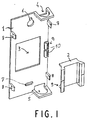
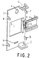
- Figures 1 and 2 show two views of a bottom and a support according to an embodiment of the invention.
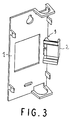
- Figure 3 shows a view of a bottom according to the embodiment of Figure 1 and a support of different dimensions.
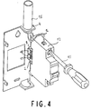
- Figure 4 shows the installation and connection of a device in a box according to Figure 3.
- Figure 5 shows a cabinet according to Figure 3 with the electrical appliance installed in its normal position of use.
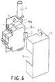
- Figure 6 shows a cabinet according to Figures 1 and 2 comprising an installed electrical appliance and a protective cover.
- the box according to an embodiment of the invention of Figure 1 has a bottom 1 intended to be fixed on a wall and a support 2 in the form of a symmetrical rail.
- the bottom 1 has an opening 3 and passages 4 and 5 for receiving arrivals or departures of electrical conduits.
- fixing the bottom to a wall, for example a wall or a partition. is made through two orifices 6 and 7.
- Lugs 8 arranged at the ends of the plate forming the bottom 1 participate in the fixing of a cover of the box.
- the support 2 in the form of a symmetrical rail has a length allowing it to receive two modular devices or one device having the width of 2 modules.
- the width of a module is generally around 18mm or 9mm.
- the support 2 is fixed to the bottom 1 using a pivoting device 9.
- the device 9 comprises a fixed part, composed for example of clips 10 preferably arranged on the edge of the bottom plate, and of a mobile part.
- the mobile part is constituted by an axis 11 which is clipped into the fixed part as shown in Figure 2. All longitudinal movement is blocked by stops 12 arranged perpendicular to the axis 11. Two stops are located at the ends of the axis 11 and one on its central part.
- the support 2 pivots relative to the bottom 1 around the axis 11 of rotation, parallel to said bottom 1 and to the fixing wall.
- Figure 3 shows a bottom according to the embodiment of Figures 1 and 2, and a support 2 having the dimensions of a single module.
- Figure 4 shows the installation and connection of an electrical device in a box having a bottom 1 and a support 2 according to Figure 3.
- the fixing is done. preferably when the support is deployed so that the device 13 is perpendicular to the bottom. In this position, the connection of an electrical conductor 14 is facilitated.
- An elongated tool like a screwdriver 15 can be used without difficulty.
- the conductor 14 arrives, in this example. by a conduit 16 crossing the passage 4.
- the device 13 When the connection is completed, the device 13 can be arranged in its normal position of use. the electrical appliance is then folded towards the bottom of the box thanks to the pivoting of the support 2 relative to the bottom 1.
- Figure 5 shows the cabinet and the apparatus of Figure 4 in its normal position of use.
- the bottom 1 is fixed by a screw 17 against a wall 18 of a wall.
- the support 2 which has pivoted vertically along an axis parallel to the bottom 1 is in a position substantially perpendicular to said bottom and to the wall.
- the apparatus is in a position where it is pressed parallel to the bottom, with a lateral face parallel to the wall 18.
- the projecting volume occupied by the cabinet is very small. It depends on the width of the device or the length of the support. In known boxes, the occupied surface projection depended on the height of the apparatus, the height being the distance between the rear face of the apparatus which is fixed on the support and the accessible front face.
- the front of the electrical device In its normal position, the front of the electrical device remains accessible, which allows a user to operate it or view it.
- the electrical appliance is protected by a cover 19 which covers the entire enclosure.
- the cover is fixed and maintained by the lugs 8.
- FIG. 6 shows an exploded view of a box, according to an embodiment of the invention, comprising a support 2 supporting two electrical devices 13a and 13b.
- the cover 19, for covering the two devices and the bottom of the box, has a notch 20 for the passage of the conduit 16 and an opening 21 to make the front faces of the devices accessible.
- the support 2 has a length making it possible to support one or two modular electrical devices. However, it is possible to use in boxes according to the invention supports of greater length.
- the pivoting fastening device described above preferably comprises a fixed part in the form of clips and a mobile part in the form of an axis. In other embodiments of the invention it is possible to reverse the fixed and mobile parts. It is also possible to use other systems allowing pivoting between the support and the bottom.
- the support 2 is preferably a plastic rail, but it may be made of any other material, for example metal.
- the shape of a symmetrical rail can also be replaced by any other form of support, for example asymmetrical rails.
Landscapes
- Engineering & Computer Science (AREA)
- Power Engineering (AREA)
- Casings For Electric Apparatus (AREA)
- Switch Cases, Indication, And Locking (AREA)
Applications Claiming Priority (2)
| Application Number | Priority Date | Filing Date | Title |
|---|---|---|---|
| FR9506073 | 1995-05-17 | ||
| FR9506073A FR2734448B1 (fr) | 1995-05-17 | 1995-05-17 | Coffret d'appareillage electrique |
Publications (2)
| Publication Number | Publication Date |
|---|---|
| EP0743730A1 true EP0743730A1 (de) | 1996-11-20 |
| EP0743730B1 EP0743730B1 (de) | 2001-10-24 |
Family
ID=9479252
Family Applications (1)
| Application Number | Title | Priority Date | Filing Date |
|---|---|---|---|
| EP19960410043 Expired - Lifetime EP0743730B1 (de) | 1995-05-17 | 1996-05-02 | Gehäuse eines elektrischen Gerätes |
Country Status (4)
| Country | Link |
|---|---|
| EP (1) | EP0743730B1 (de) |
| DE (1) | DE69616145T2 (de) |
| ES (1) | ES2164857T3 (de) |
| FR (1) | FR2734448B1 (de) |
Cited By (3)
| Publication number | Priority date | Publication date | Assignee | Title |
|---|---|---|---|---|
| FR2885457A1 (fr) * | 2005-05-04 | 2006-11-10 | Legrand France | Enveloppe de distribution pour installation electrique et ensemble comportant une telle enveloppe |
| US8780534B2 (en) | 2011-09-21 | 2014-07-15 | Schneider Electric USA, Inc. | Swing out mount |
| CN105667336A (zh) * | 2016-03-08 | 2016-06-15 | 上海埃而生电气有限公司 | 模块化智能高压配电箱 |
Families Citing this family (1)
| Publication number | Priority date | Publication date | Assignee | Title |
|---|---|---|---|---|
| FR3153700B1 (fr) * | 2023-09-28 | 2025-10-10 | Eurohm | Coffret pour appareillages électriques modulaires |
Citations (4)
| Publication number | Priority date | Publication date | Assignee | Title |
|---|---|---|---|---|
| DE1926280U (de) * | 1965-06-25 | 1965-11-04 | Licentia Gmbh | Befestigungseinrichtung fuer schmalbau-installationsgeraete. |
| DE1993996U (de) * | 1968-05-04 | 1968-09-19 | Bbc Brown Boveri & Cie | Geraetetragschiene zur halterung von installationsgeraeten. |
| DE2952619A1 (de) * | 1979-12-28 | 1981-07-09 | Mainland Elektro-, Sanitär- und Eisenwaren-Großhandels GmbH, 8772 Marktheidenfeld | Verteilergehaeuse |
| EP0352149A1 (de) * | 1988-07-04 | 1990-01-24 | Telemecanique | Vorrichtung zur Halterung von elektrischen Geräten |
-
1995
- 1995-05-17 FR FR9506073A patent/FR2734448B1/fr not_active Expired - Fee Related
-
1996
- 1996-05-02 ES ES96410043T patent/ES2164857T3/es not_active Expired - Lifetime
- 1996-05-02 EP EP19960410043 patent/EP0743730B1/de not_active Expired - Lifetime
- 1996-05-02 DE DE1996616145 patent/DE69616145T2/de not_active Expired - Fee Related
Patent Citations (4)
| Publication number | Priority date | Publication date | Assignee | Title |
|---|---|---|---|---|
| DE1926280U (de) * | 1965-06-25 | 1965-11-04 | Licentia Gmbh | Befestigungseinrichtung fuer schmalbau-installationsgeraete. |
| DE1993996U (de) * | 1968-05-04 | 1968-09-19 | Bbc Brown Boveri & Cie | Geraetetragschiene zur halterung von installationsgeraeten. |
| DE2952619A1 (de) * | 1979-12-28 | 1981-07-09 | Mainland Elektro-, Sanitär- und Eisenwaren-Großhandels GmbH, 8772 Marktheidenfeld | Verteilergehaeuse |
| EP0352149A1 (de) * | 1988-07-04 | 1990-01-24 | Telemecanique | Vorrichtung zur Halterung von elektrischen Geräten |
Cited By (3)
| Publication number | Priority date | Publication date | Assignee | Title |
|---|---|---|---|---|
| FR2885457A1 (fr) * | 2005-05-04 | 2006-11-10 | Legrand France | Enveloppe de distribution pour installation electrique et ensemble comportant une telle enveloppe |
| US8780534B2 (en) | 2011-09-21 | 2014-07-15 | Schneider Electric USA, Inc. | Swing out mount |
| CN105667336A (zh) * | 2016-03-08 | 2016-06-15 | 上海埃而生电气有限公司 | 模块化智能高压配电箱 |
Also Published As
| Publication number | Publication date |
|---|---|
| DE69616145T2 (de) | 2002-06-06 |
| FR2734448B1 (fr) | 1997-06-27 |
| DE69616145D1 (de) | 2001-11-29 |
| EP0743730B1 (de) | 2001-10-24 |
| ES2164857T3 (es) | 2002-03-01 |
| FR2734448A1 (fr) | 1996-11-22 |
Similar Documents
| Publication | Publication Date | Title |
|---|---|---|
| FR2780206A1 (fr) | Ensemble formant bloc de distribution d'energie, et barre omnibus de transmission d'energie | |
| FR2743448A1 (fr) | Agencement d'interconnexion pour appareillage electrique, notamment pour appareillage de type bloc de jonction, et boitier equipe d'un tel agencement | |
| EP0772256B1 (de) | Elektrisches Gerät mit Anschlussklemmen, die durch eine Blende mit Flügeln geschützt sind | |
| EP0743730B1 (de) | Gehäuse eines elektrischen Gerätes | |
| EP0908915A1 (de) | Gehäuse für ein elektrisches Gerät, wie ein Lastschalter | |
| FR2716304A1 (fr) | Dispositif d'installation électrique à platine support équipé d'une bride de raccordement. | |
| EP3503318B1 (de) | Stromverteilungsvorrichtung, insbesondere in einem elektrischen schaltschrank oder einer elektrischen schalttafel | |
| EP1146619B1 (de) | Rahmenschenkel für ein Rahmengestell, als Leiter zur Verteilung elektrischer Energie | |
| EP0908972B1 (de) | Kabelzugentlastung und ein elektrisches Gerät ausgerüstet mit einer solchen Kabelzugentlastung | |
| EP0355233B1 (de) | Isolierter Anschlusskasten, insbesondere für Montage in Lichtmasten | |
| FR2797356A1 (fr) | Appareillage electrique muni d'un capot auxiliaire | |
| EP0342095B1 (de) | Vorrichtung zum mechanischen Schützen einer Leiterplatte, insbesondere eines Chassis eines Farbfernsehgeräts | |
| FR2769137A1 (fr) | Connecteur electrique | |
| EP0860901A1 (de) | Gehäuse für elektrischen Gerät und elektrische Vorrichtung mit einem solchen Gehäuse | |
| EP0743728A1 (de) | Gehäuse eines elektrischen Gerätes | |
| FR3101193A1 (fr) | Appareil de coupure électrique à fusible | |
| EP3524879A1 (de) | Dichter sicherheitsbeleuchtungsblock | |
| EP0800192B1 (de) | Elektrisches Gerät mit einem Schütz mit einer Aufnahmevorrichtung für ein Schutzmodul und Schutzmodul | |
| EP1505703A1 (de) | Schutzvorrichtung für eine Abzweigdose | |
| FR3154246A1 (fr) | Système de distribution de courant et ensemble d’alimentation électrique comprenant un tel système de distribution | |
| FR2620580A1 (fr) | Coffret d'alimentation pour comptage electrique | |
| EP1195858B1 (de) | Führungskanal-Einrichtung mit Kabelbefestigung | |
| BE1006966A5 (fr) | Dispositif de fixation de profiles avec au moins une barre conductrice et profile pour etre utilise avec ce dispositif de fixation. | |
| FR2900508A1 (fr) | Barre omnibus pour repartition electrique | |
| FR2845835A1 (fr) | Goulotte pourvue d'au moins un moyen de continuite des separations au niveau des jonctions droites ou angulaires |
Legal Events
| Date | Code | Title | Description |
|---|---|---|---|
| PUAI | Public reference made under article 153(3) epc to a published international application that has entered the european phase |
Free format text: ORIGINAL CODE: 0009012 |
|
| AK | Designated contracting states |
Kind code of ref document: A1 Designated state(s): DE ES GB IT |
|
| 17P | Request for examination filed |
Effective date: 19970412 |
|
| 17Q | First examination report despatched |
Effective date: 19990510 |
|
| RAP1 | Party data changed (applicant data changed or rights of an application transferred) |
Owner name: SCHNEIDER ELECTRIC INDUSTRIES SA |
|
| RAP1 | Party data changed (applicant data changed or rights of an application transferred) |
Owner name: SCHNEIDER ELECTRIC INDUSTRIES SA |
|
| GRAG | Despatch of communication of intention to grant |
Free format text: ORIGINAL CODE: EPIDOS AGRA |
|
| GRAG | Despatch of communication of intention to grant |
Free format text: ORIGINAL CODE: EPIDOS AGRA |
|
| GRAH | Despatch of communication of intention to grant a patent |
Free format text: ORIGINAL CODE: EPIDOS IGRA |
|
| GRAH | Despatch of communication of intention to grant a patent |
Free format text: ORIGINAL CODE: EPIDOS IGRA |
|
| GRAA | (expected) grant |
Free format text: ORIGINAL CODE: 0009210 |
|
| AK | Designated contracting states |
Kind code of ref document: B1 Designated state(s): DE ES GB IT |
|
| REF | Corresponds to: |
Ref document number: 69616145 Country of ref document: DE Date of ref document: 20011129 |
|
| REG | Reference to a national code |
Ref country code: GB Ref legal event code: IF02 |
|
| GBT | Gb: translation of ep patent filed (gb section 77(6)(a)/1977) |
Effective date: 20020105 |
|
| REG | Reference to a national code |
Ref country code: ES Ref legal event code: FG2A Ref document number: 2164857 Country of ref document: ES Kind code of ref document: T3 |
|
| PGFP | Annual fee paid to national office [announced via postgrant information from national office to epo] |
Ref country code: DE Payment date: 20020502 Year of fee payment: 7 |
|
| RAP2 | Party data changed (patent owner data changed or rights of a patent transferred) |
Owner name: SCHNEIDER ELECTRIC INDUSTRIES SAS |
|
| PLBE | No opposition filed within time limit |
Free format text: ORIGINAL CODE: 0009261 |
|
| STAA | Information on the status of an ep patent application or granted ep patent |
Free format text: STATUS: NO OPPOSITION FILED WITHIN TIME LIMIT |
|
| 26N | No opposition filed | ||
| PG25 | Lapsed in a contracting state [announced via postgrant information from national office to epo] |
Ref country code: DE Free format text: LAPSE BECAUSE OF NON-PAYMENT OF DUE FEES Effective date: 20031202 |
|
| PGFP | Annual fee paid to national office [announced via postgrant information from national office to epo] |
Ref country code: GB Payment date: 20120502 Year of fee payment: 17 |
|
| PGFP | Annual fee paid to national office [announced via postgrant information from national office to epo] |
Ref country code: IT Payment date: 20120512 Year of fee payment: 17 |
|
| PGFP | Annual fee paid to national office [announced via postgrant information from national office to epo] |
Ref country code: ES Payment date: 20120607 Year of fee payment: 17 |
|
| GBPC | Gb: european patent ceased through non-payment of renewal fee |
Effective date: 20130502 |
|
| PG25 | Lapsed in a contracting state [announced via postgrant information from national office to epo] |
Ref country code: IT Free format text: LAPSE BECAUSE OF NON-PAYMENT OF DUE FEES Effective date: 20130502 |
|
| PG25 | Lapsed in a contracting state [announced via postgrant information from national office to epo] |
Ref country code: GB Free format text: LAPSE BECAUSE OF NON-PAYMENT OF DUE FEES Effective date: 20130502 |
|
| REG | Reference to a national code |
Ref country code: ES Ref legal event code: FD2A Effective date: 20140609 |
|
| PG25 | Lapsed in a contracting state [announced via postgrant information from national office to epo] |
Ref country code: ES Free format text: LAPSE BECAUSE OF NON-PAYMENT OF DUE FEES Effective date: 20130503 |