EP0743735A2 - Dispositif de regroupement de lignes d'alimentation dans un bâtiment - Google Patents
Dispositif de regroupement de lignes d'alimentation dans un bâtiment Download PDFInfo
- Publication number
- EP0743735A2 EP0743735A2 EP96107920A EP96107920A EP0743735A2 EP 0743735 A2 EP0743735 A2 EP 0743735A2 EP 96107920 A EP96107920 A EP 96107920A EP 96107920 A EP96107920 A EP 96107920A EP 0743735 A2 EP0743735 A2 EP 0743735A2
- Authority
- EP
- European Patent Office
- Prior art keywords
- channel
- building
- arrangement according
- floor
- lines
- Prior art date
- Legal status (The legal status is an assumption and is not a legal conclusion. Google has not performed a legal analysis and makes no representation as to the accuracy of the status listed.)
- Granted
Links
Images




Classifications
-
- H—ELECTRICITY
- H02—GENERATION; CONVERSION OR DISTRIBUTION OF ELECTRIC POWER
- H02G—INSTALLATION OF ELECTRIC CABLES OR LINES, OR OF COMBINED OPTICAL AND ELECTRIC CABLES OR LINES
- H02G3/00—Installations of electric cables or lines or protective tubing therefor in or on buildings, equivalent structures or vehicles
- H02G3/02—Details
- H02G3/08—Distribution boxes; Connection or junction boxes
- H02G3/18—Distribution boxes; Connection or junction boxes providing line outlets
-
- H—ELECTRICITY
- H02—GENERATION; CONVERSION OR DISTRIBUTION OF ELECTRIC POWER
- H02G—INSTALLATION OF ELECTRIC CABLES OR LINES, OR OF COMBINED OPTICAL AND ELECTRIC CABLES OR LINES
- H02G3/00—Installations of electric cables or lines or protective tubing therefor in or on buildings, equivalent structures or vehicles
- H02G3/02—Details
- H02G3/04—Protective tubing or conduits, e.g. cable ladders or cable troughs
- H02G3/0425—Plinths
-
- H—ELECTRICITY
- H02—GENERATION; CONVERSION OR DISTRIBUTION OF ELECTRIC POWER
- H02G—INSTALLATION OF ELECTRIC CABLES OR LINES, OR OF COMBINED OPTICAL AND ELECTRIC CABLES OR LINES
- H02G3/00—Installations of electric cables or lines or protective tubing therefor in or on buildings, equivalent structures or vehicles
- H02G3/28—Installations of cables, lines, or separate protective tubing therefor in conduits or ducts pre-established in walls, ceilings or floors
- H02G3/283—Installations of cables, lines, or separate protective tubing therefor in conduits or ducts pre-established in walls, ceilings or floors in floors
Definitions
- Supply lines such as water, power lines, gas lines are usually routed separately from one another in a building, with such lines nowadays being plastered in the building walls. This requires slitting the walls of the shell in a vertical, horizontal and sometimes even oblique direction. This is expensive.
- the invention has for its object to provide an arrangement for bundling supply lines in the Construction phase can be installed with minimal effort and is particularly user-friendly in the use phase due to its "transparency" without the aid of a line plan.
- an arrangement for bundling at least the essential supply lines for a building in the form of a channel is provided according to the invention, which is arranged in the joint region of the wall and floor.
- At least partial sections of the channel expediently run along the inside of the outer wall of the building, it being possible, in particular in the case of a multi-story building, to provide an open ring (for example by the staircase) interrupted on each floor.
- the or each channel (per floor) can also have a central section which is directly connected to the electricity, heating and water supply of the building, from which partial sections branch off finger-shaped into the individual rooms.
- the channels on the different floors are advantageously connected to one another by a rising channel with the electricity, heating and water supply housed in the basement or ground floor.
- This can be a continuous canal from the basement to the top floor.
- the channel on the ground floor can also be connected to the energy supply in the basement via a direct breakthrough, while the channel on the upper floor is connected via its own riser.
- the supply lines generally contain at least one heating or cooling air line, one of which is heat-insulated cold and hot water line and power lines, preferably in separate sections of the duct.
- Connection lines for telephone, Television, PC, antenna and the like belong.
- One or more gas lines and possibly a vacuum hose can also be accommodated in the channel.
- the or each channel is substantially sunk in the floor and has outlets and switches for the supply lines.
- the outlets are advantageously provided in a bar shaped like a conventional baseboard. This bar can be detachably connected to the channel, in particular by snapping it on, in order to ensure easy access, in particular in the case of maintenance.
- an arrangement is particularly simple in which the channel and optionally the strip are divided into elements of standardized length which are designed to be collapsible for assembly. This enables large-scale production in the factory.
- the arrangement according to the invention also offers significant advantages in the heating installation and the connection of domestic sanitary facilities, electrical household appliances and devices for entertainment and communication such as television, radio, PC and telephone. Connections and switches for all of these devices can all be accommodated in the joint area between the wall and the floor, although in exceptional cases, e.g. for service water pipes, installation under plaster from the wall-floor area to a sink outlet, a bathtub or the like. Is possible.
- connection parts Due to the prefabrication of the duct parts including those parts that are provided with connections, these connection parts can be subsequently arranged at any point in the room without damaging the wall or floor.
- a particularly elegant solution is characterized in that only a conventional baseboard or wall strip is visible in the interior as part of the channel, the larger parts of the channel being recessed in the floor or in the wall area near the floor. In this baseboard, the outlets, switches and the like are then housed, where they are still easily accessible.
- the baseboard can be detachably connected to the channel by means of a snap or plug connection, which makes maintenance or repair work and subsequent local relocation of connection, tap or switching points very simple.
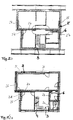
- the floor plans according to FIGS. 1a and 1b each show a thick, open ring channel 2 and 2 'containing the essential supply lines for the floor in question.
- the ring channels 2, 2 ' are interrupted, namely on the ground floor through the entrance area 3, stairwell 4 and on the upper floor through the entire front side 5 of the building.
- the ring channels 2, 2 ' are connected to one another and to the electricity, heating and water supply (not shown) housed in the basement of the building by means of a riser channel 6 indicated at 6 in FIGS. 1a and 1b.
- the ring channel 2 on the ground floor may also contain a gas line, but not the ring channel on the upper floor according to FIG. 2, in which no cooking facilities are provided.
- the channel again designated as a whole by reference number 2 on the ground floor and 2 'on the upper floor, has a central section which is connected directly to the riser channel 6. From this central section, individual channel sections 2a, 2'a; 2b, 2'b; 2c, 2'c; 2d, 2'd finger-shaped to the individual tapping points or air outlets 2f, 2'f, in the rooms of the building, the air outlets preferably being provided under windows.
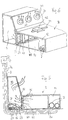
- Channel 2 contains an im essentially in the bottom of the ground floor recessed channel body 10, which contains a total of four compartments 12, 14, 16 and 18.
- the compartment 14 is connected to the heating system, which is usually arranged in the basement and provides heated heating air which is introduced into the compartment 14 in a manner not shown.
- the compartment 16, which contains the power lines 20 mentioned, communicates with the compartment 14 via lateral slots 22 in a partition 23.
- Compartment 18 is placed on floor 9 in the joint area between wall 8 and floor 9 in the manner of a conventional baseboard and thus forms the only part of channel 2 that is visible from the interior.
- outlets such as a socket 28 for a plug 29, air nozzles 30 for discharging the heating air into the interior, and switches, e.g. Light switch (not shown) provided.
- switches e.g. Light switch (not shown) provided.
- slots 24 for direct introduction of the heating air into the interior are only provided in a door opening area in which the compartment 18 is interrupted due to a door opening 32.
- the compartments 16, 18 merge directly into one another, as shown in FIG. 6.
- the compartment 18 can be lined with sound-absorbing material, preferably in the region of the wall 8, in order to dampen noises, such as flow noises of liquid and air, as well as the propagation of sound that occurs outside the room in question.
- a support 38 in the form of a carpeted floor, parquet floor, a tiled floor or the like can also be provided as usual.
- the compartment 16 receiving the power lines 20 is here separated from the compartment 18 by a partition 17.
- a slide 40 is arranged, which is displaceable via a handle 42 from the top of the floor along a slot 44 and thus horizontally parallel along the partition 23 containing the slots 22 between the compartments 14 and 18.
- the slider 40 contains at least one opening 41.
- a vacuum hose 49 is additionally accommodated in the compartment 18 directly above the compartment 16 for the power lines 20, which can communicate with a suction fan installed in the basement, for example.
- the compartment 12 for receiving the cold and hot water pipes 7 is shown open at the top in FIGS. 7 to 10, but in practice is covered by a floor covering 38 or another cover at the top. Finally, in FIGS. 7 to 12, the strip 26 covering the compartment 18 at the top is not drawn for the sake of simplicity.
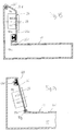
- FIG. 7 shows a rounded corner section 50 of the duct 2 in the corner of an interior of the building, on which two walls abut one another at an angle of 90 °.
- the compartment 12 is delimited by quarter arcs 52, 53, while the compartments 16, 18 for guiding the power lines 20 and the vacuum hose 49 are only delimited on the inside by a quarter circle 55.
- a strip corner element 56 serves to connect the strips 26 (not shown).
- FIG. 8 shows a branching section 60 of the channel 2, with this branching section 60 being vertically followed by a riser channel, not shown, for receiving vertical branch lines of all the lines accommodated in the channel 2, including the water lines 7 and the power lines 20.
- the branching section 60 has a vertically upwardly extending part 62 with plug-in connection parts 64, 66, 68 for plugging the riser, whereby through the part 66 the electrical lines and possibly the vacuum cleaner hose, through the part 64 the hot or cold air and through the part 68 the hot and cold water pipes are branched up to the next floor from the horizontal pipes.
- FIG. 9 shows a channel element 70 of the channel 2, which is designed to be inserted into one another with other similarly shaped channel elements.
- the channel element 70 has a more or less inner channel element 74 which can be pushed in or out of an outer element 72 in the direction of the arrow and which forms the compartment 14.
- the inner channel element can be locked relative to the outer channel element 76 by means of a screw 76. In this way, distances of different lengths between duct elements of standardized length can be compensated, which are prefabricated in the factory and are assembled at the construction site into ring ducts 2, 2 '.
- FIG. 10 shows two different channel elements 78, 79 of this type, of which the channel element 78 is equipped with a slide 40 with an actuating handle 42 according to FIG. 6.
- the channel element 78 is equipped with a slide 40 with an actuating handle 42 according to FIG. 6.
- a piece of a bar which is designed here as an angle profile and can be snapped onto the channel is shown.
- 11 to 15 essentially show modifications of the attachment of a strip 26 which closes off the channel at the top in the visible region of the interior, which despite the structural differences is given the same reference number throughout these figures for the sake of simplicity.
- the strip 26 forms a hollow profile which is only open at the bottom and which encloses the compartment 18 of the channel.
- the strip 26 has two parallel legs 26a, 26b which can be deflected into a U-profile which is open at the top and which forms the compartment 16.
- slots 22 are provided, via which heating air can pass from the compartment 14 into the compartment 16 and from there via the space between the legs 26a, 26b into the compartment 18.
- the cooling air emerges from the compartment 18 via the round nozzles 30 accommodated in a front wall part 26c of the strip 26.
- these round nozzles have spherical inserts 30a, which allow adjustment by hand and thus a variation in the direction of the hot air outlet.
- FIG. 12 shows an arrangement with the strip 26 designed in the same way as in FIG. 11, but with a section at the level of a socket 28 with the plug inserted Plug 29 is shown.
- a further modification, however, is that there are no air nozzles 30 in the strip 26, but in this case the air is provided directly from the compartment 14 into a floor area via outlet slots 24a in a riser section 14a of the compartment 14.
- the construction according to FIG. 13 is modified insofar as the bar 26 here forms an angle profile which has a horizontal angle section 26d and an inclined bar section 26c containing nozzles 30, other connections and switches.
- the inclined strip section 26c has a hook 26e at its lower end, with which it engages behind a projection 10a on the channel body 10.
- the horizontal angle section 26d engages with a vertical hook section 26f behind a projection 10b on a wall section 10c of the channel body.
- the embodiments of the strip 26 shown in FIGS. 11 to 13 require a resiliently elastic design so that the strip can be snapped onto the channel body 10 by spreading.
- FIGS. 14 and 15 show two further modifications of the channel body 10, the bar 26 in FIG. 14 basically being designed as in the embodiment according to FIGS. 3 to 6.
- the strip 26 is connected to the channel body 10 as follows: at its upper end, the channel body 10 has a web section 10d equipped with a permanent magnet 80.
- the horizontal wall 10f of the channel body above the compartment 14 has at its left end in FIG. 14 an obliquely upward neck 10g with a receiving groove 10h.
- the bar 26 is inserted with its lower end into this receiving groove 10h for assembly and attracted and held by the magnet 80 with its upper end.
- the strip is shaped into an angular profile and is engaged with a hook 26f on an upper leg 26d of the strip profile 26 in a receiving groove of a thickening 10k at the upper end of a raised rear wall 10m of the channel body 10.
- a horizontal web 26e at the lower end of a vertical leg 26c of the strip 26 engages behind a projection 10n at the left end of the section of the channel body 10 delimiting the compartment 14, this projection 10n being provided with a permanent magnet 80.
- the strip 26 is hooked into the groove 10k and is easily removed by the magnet 80 in the projection 10n.
- the strips 26 of the designs according to FIGS. 14 and 15 are made of a ferromagnetic, elastic material, while they may also consist of a non-magnetic material, such as a plastic.
- the duct system according to the invention can contain not only feed lines but also return lines, e.g. the process water drain pipes. However, it should not be practical to also drain the toilets through channels 2 and 2 '. In practice, separate sewage pipes will be provided as usual.
- the channel elements shown in FIGS. 9 and 10 can have different lengths, so that a large-scale production of the channel elements, the connection elements, which are equipped with connection openings, switch openings, etc., as well as separate corner sections according to FIG. 7 and branching sections according to FIG. 8 is possible . This considerably simplifies and speeds up installation on the construction site.
Landscapes
- Engineering & Computer Science (AREA)
- Architecture (AREA)
- Civil Engineering (AREA)
- Structural Engineering (AREA)
- Installation Of Indoor Wiring (AREA)
- Building Environments (AREA)
- Floor Finish (AREA)
- Packages (AREA)
- Buffer Packaging (AREA)
Applications Claiming Priority (2)
| Application Number | Priority Date | Filing Date | Title |
|---|---|---|---|
| DE19517984A DE19517984C2 (de) | 1995-05-16 | 1995-05-16 | Anordnung zur Bündelung von Versorgungsleitungen für ein Gebäude |
| DE19517984 | 1995-05-16 |
Publications (3)
| Publication Number | Publication Date |
|---|---|
| EP0743735A2 true EP0743735A2 (fr) | 1996-11-20 |
| EP0743735A3 EP0743735A3 (fr) | 1999-05-12 |
| EP0743735B1 EP0743735B1 (fr) | 2005-03-02 |
Family
ID=7762069
Family Applications (1)
| Application Number | Title | Priority Date | Filing Date |
|---|---|---|---|
| EP96107920A Expired - Lifetime EP0743735B1 (fr) | 1995-05-16 | 1996-05-17 | Dispositif de regroupement de lignes d'alimentation dans un bâtiment |
Country Status (3)
| Country | Link |
|---|---|
| EP (1) | EP0743735B1 (fr) |
| AT (1) | ATE290260T1 (fr) |
| DE (2) | DE19517984C2 (fr) |
Cited By (4)
| Publication number | Priority date | Publication date | Assignee | Title |
|---|---|---|---|---|
| GB2372642A (en) * | 2001-02-23 | 2002-08-28 | Hager Ltd | Inclined electrical wall socket |
| EP1396590A4 (fr) * | 2001-06-14 | 2004-06-23 | Nozomu Saruhashi | Structure d'agencement de panneaux de bureau |
| NL1025367C2 (nl) * | 2004-01-30 | 2005-09-20 | Harm Veenstra | Cementdekvloerkabelgoot. |
| EP1452656B1 (fr) * | 2003-02-26 | 2008-09-17 | Xella Baustoffe GmbH | Procédé de renovation d'un mur d'une pièce d'une construction |
Families Citing this family (3)
| Publication number | Priority date | Publication date | Assignee | Title |
|---|---|---|---|---|
| DE102008011348B4 (de) | 2008-02-27 | 2023-09-28 | Pluggit Gmbh | Lüftungssystem und Gebäude mit einem Lüftungssystem |
| DE102018006346A1 (de) * | 2018-08-13 | 2020-02-13 | Jochen Kehl | Innenausbausystem sowie Verfahren zur Herstellung einer Bodenkonstruktion als Bestandteil eines Innenausbausystems |
| DE202018003752U1 (de) | 2018-08-14 | 2018-12-06 | Jochen Kehl | Innenausbausystem |
Family Cites Families (7)
| Publication number | Priority date | Publication date | Assignee | Title |
|---|---|---|---|---|
| US2680775A (en) * | 1949-03-19 | 1954-06-08 | Robertson Co H H | Wire distributing system |
| GB1442046A (en) * | 1974-03-22 | 1976-07-07 | Davis Truniing Ltd | Trunking for electric wiring |
| SE7602198L (sv) * | 1976-02-24 | 1977-08-25 | Tore Georg Palmaer | Installationssystem |
| EP0305338B1 (fr) * | 1987-08-28 | 1993-02-03 | Ulrich Gantenbein | Ensemble de pièces et son utilisation pour la construction de conduits et de boîtiers dans un immeuble |
| DE8711850U1 (de) * | 1987-09-02 | 1987-10-22 | Zwanziger, Helmuth, 2820 Bremen | Sockelleiste |
| DE9305502U1 (de) * | 1993-04-13 | 1993-06-24 | OBO Bettermann oHG, 5750 Menden | Unterflur-Installationskanal |
| DE9315256U1 (de) * | 1993-10-09 | 1994-02-10 | Pfennig, Lothar, Dipl.-Ing., 07551 Gera | Leitungsführungskanal für unterschiedliche Versorgungsmedien |
-
1995
- 1995-05-16 DE DE19517984A patent/DE19517984C2/de not_active Expired - Fee Related
-
1996
- 1996-05-17 DE DE59611202T patent/DE59611202D1/de not_active Expired - Fee Related
- 1996-05-17 AT AT96107920T patent/ATE290260T1/de not_active IP Right Cessation
- 1996-05-17 EP EP96107920A patent/EP0743735B1/fr not_active Expired - Lifetime
Cited By (6)
| Publication number | Priority date | Publication date | Assignee | Title |
|---|---|---|---|---|
| GB2372642A (en) * | 2001-02-23 | 2002-08-28 | Hager Ltd | Inclined electrical wall socket |
| GB2372642B (en) * | 2001-02-23 | 2004-12-22 | Hager Ltd | Wiring accessories |
| EP1396590A4 (fr) * | 2001-06-14 | 2004-06-23 | Nozomu Saruhashi | Structure d'agencement de panneaux de bureau |
| AU2001274529B2 (en) * | 2001-06-14 | 2006-01-05 | Nozomu Sahashi | Office panel arrangement structure |
| EP1452656B1 (fr) * | 2003-02-26 | 2008-09-17 | Xella Baustoffe GmbH | Procédé de renovation d'un mur d'une pièce d'une construction |
| NL1025367C2 (nl) * | 2004-01-30 | 2005-09-20 | Harm Veenstra | Cementdekvloerkabelgoot. |
Also Published As
| Publication number | Publication date |
|---|---|
| DE19517984A1 (de) | 1996-11-21 |
| EP0743735B1 (fr) | 2005-03-02 |
| ATE290260T1 (de) | 2005-03-15 |
| DE19517984C2 (de) | 2001-08-30 |
| EP0743735A3 (fr) | 1999-05-12 |
| DE59611202D1 (de) | 2005-04-07 |
Similar Documents
| Publication | Publication Date | Title |
|---|---|---|
| DE2052973A1 (de) | Vorsorgungszelle fur Wohneinheiten | |
| DE2252006A1 (de) | Transportfaehige bausystemgruppe zum einbau in gebaeude | |
| EP1893052A1 (fr) | Dispositif pour poser des cuisines | |
| DE19517984C2 (de) | Anordnung zur Bündelung von Versorgungsleitungen für ein Gebäude | |
| EP0013987B1 (fr) | Elément de cloison préfabriqué avec tuyauterie incorporée notamment pour salle d'eau, local sanitaire, cuisine ou analogue | |
| DE102007057003A1 (de) | Vorwandsystem für die Gebäude-Systemtechnik | |
| DE19639770C2 (de) | Verfahren und Bausatz zur Verkleidung und Verrohrung von Sanitärräumen | |
| DE3226742A1 (de) | Vorgefertigte raumzelle | |
| CH716647B1 (de) | Sanitäreinrichtung mit zumindest zwei wasserführenden Funktionsmodulen. | |
| EP2445069A1 (fr) | Système de profilé d'angle | |
| EP0305338B1 (fr) | Ensemble de pièces et son utilisation pour la construction de conduits et de boîtiers dans un immeuble | |
| DE7203557U (de) | Vorfabrizierter sanitaerblock | |
| DE9110913U1 (de) | Sanitärelement | |
| EP0724677A1 (fr) | Maison d'habitation et cellule prefabriquee utilisable preferentiellement lors de la construction de cette maison | |
| DE871510C (de) | Vorfabrizierte Hausinstallation | |
| DE3103511C2 (de) | Sanitärgerät, das auf einem um seine senkrechte Mittelachse drehbaren Drehteller angeordnet ist | |
| DE7514879U (de) | Vorgefertigte Trennwand zur Unterteilung von Räumen innerhalb von Gebäuden | |
| DE202005017279U1 (de) | Unterflur-Kabelkanalsystem | |
| EP1112415B1 (fr) | Dispositif dote d'elements sanitaires et/ou de cuisine | |
| DE939051C (de) | Vorfabriziertes Wandelement fuer Trag- oder Trennungsmauern | |
| DE1434709C (de) | Zwei oder mehrgeschossiges Fertig haus aus Raumkasten | |
| DE4413776A1 (de) | System und Verfahren für die Sanitärinstallation | |
| DE3436073A1 (de) | Kupplungsstueck fuer einen kabelkanal | |
| CH716183A2 (de) | Raum-Modul mit Installationen. | |
| WO2021191227A1 (fr) | Bâtiment à plusieurs étages, en particulier bâtiment d'appartements ou bâtiment de bureaux, et élément de construction de support préfabriqué pour un tel bâtiment à plusieurs étages |
Legal Events
| Date | Code | Title | Description |
|---|---|---|---|
| PUAI | Public reference made under article 153(3) epc to a published international application that has entered the european phase |
Free format text: ORIGINAL CODE: 0009012 |
|
| AK | Designated contracting states |
Kind code of ref document: A2 Designated state(s): AT BE CH DE DK ES FR GB IT LI NL SE |
|
| PUAL | Search report despatched |
Free format text: ORIGINAL CODE: 0009013 |
|
| AK | Designated contracting states |
Kind code of ref document: A3 Designated state(s): AT BE CH DE DK ES FR GB IT LI NL SE |
|
| 17P | Request for examination filed |
Effective date: 19990413 |
|
| RAP1 | Party data changed (applicant data changed or rights of an application transferred) |
Owner name: HERMS, MARC |
|
| 17Q | First examination report despatched |
Effective date: 20021011 |
|
| GRAP | Despatch of communication of intention to grant a patent |
Free format text: ORIGINAL CODE: EPIDOSNIGR1 |
|
| GRAS | Grant fee paid |
Free format text: ORIGINAL CODE: EPIDOSNIGR3 |
|
| GRAA | (expected) grant |
Free format text: ORIGINAL CODE: 0009210 |
|
| RIC1 | Information provided on ipc code assigned before grant |
Ipc: 7H 02G 3/04 B Ipc: 7H 02G 3/38 A |
|
| AK | Designated contracting states |
Kind code of ref document: B1 Designated state(s): AT BE CH DE DK ES FR GB IT LI NL SE |
|
| PG25 | Lapsed in a contracting state [announced via postgrant information from national office to epo] |
Ref country code: NL Free format text: LAPSE BECAUSE OF FAILURE TO SUBMIT A TRANSLATION OF THE DESCRIPTION OR TO PAY THE FEE WITHIN THE PRESCRIBED TIME-LIMIT Effective date: 20050302 Ref country code: IT Free format text: LAPSE BECAUSE OF FAILURE TO SUBMIT A TRANSLATION OF THE DESCRIPTION OR TO PAY THE FEE WITHIN THE PRESCRIBED TIME-LIMIT;WARNING: LAPSES OF ITALIAN PATENTS WITH EFFECTIVE DATE BEFORE 2007 MAY HAVE OCCURRED AT ANY TIME BEFORE 2007. THE CORRECT EFFECTIVE DATE MAY BE DIFFERENT FROM THE ONE RECORDED. Effective date: 20050302 Ref country code: GB Free format text: LAPSE BECAUSE OF FAILURE TO SUBMIT A TRANSLATION OF THE DESCRIPTION OR TO PAY THE FEE WITHIN THE PRESCRIBED TIME-LIMIT Effective date: 20050302 Ref country code: FR Free format text: LAPSE BECAUSE OF NON-PAYMENT OF DUE FEES Effective date: 20050302 |
|
| REG | Reference to a national code |
Ref country code: GB Ref legal event code: FG4D Free format text: NOT ENGLISH |
|
| REG | Reference to a national code |
Ref country code: CH Ref legal event code: EP |
|
| REF | Corresponds to: |
Ref document number: 59611202 Country of ref document: DE Date of ref document: 20050407 Kind code of ref document: P |
|
| PG25 | Lapsed in a contracting state [announced via postgrant information from national office to epo] |
Ref country code: AT Free format text: LAPSE BECAUSE OF NON-PAYMENT OF DUE FEES Effective date: 20050517 |
|
| PG25 | Lapsed in a contracting state [announced via postgrant information from national office to epo] |
Ref country code: LI Free format text: LAPSE BECAUSE OF NON-PAYMENT OF DUE FEES Effective date: 20050531 Ref country code: CH Free format text: LAPSE BECAUSE OF NON-PAYMENT OF DUE FEES Effective date: 20050531 Ref country code: BE Free format text: LAPSE BECAUSE OF NON-PAYMENT OF DUE FEES Effective date: 20050531 |
|
| PG25 | Lapsed in a contracting state [announced via postgrant information from national office to epo] |
Ref country code: DK Free format text: LAPSE BECAUSE OF FAILURE TO SUBMIT A TRANSLATION OF THE DESCRIPTION OR TO PAY THE FEE WITHIN THE PRESCRIBED TIME-LIMIT Effective date: 20050602 |
|
| PG25 | Lapsed in a contracting state [announced via postgrant information from national office to epo] |
Ref country code: ES Free format text: LAPSE BECAUSE OF FAILURE TO SUBMIT A TRANSLATION OF THE DESCRIPTION OR TO PAY THE FEE WITHIN THE PRESCRIBED TIME-LIMIT Effective date: 20050613 |
|
| NLV1 | Nl: lapsed or annulled due to failure to fulfill the requirements of art. 29p and 29m of the patents act | ||
| GBV | Gb: ep patent (uk) treated as always having been void in accordance with gb section 77(7)/1977 [no translation filed] |
Effective date: 20050302 |
|
| BERE | Be: lapsed |
Owner name: HERMS, MARC Effective date: 20050531 |
|
| PG25 | Lapsed in a contracting state [announced via postgrant information from national office to epo] |
Ref country code: DE Free format text: LAPSE BECAUSE OF NON-PAYMENT OF DUE FEES Effective date: 20051201 |
|
| PLBE | No opposition filed within time limit |
Free format text: ORIGINAL CODE: 0009261 |
|
| STAA | Information on the status of an ep patent application or granted ep patent |
Free format text: STATUS: NO OPPOSITION FILED WITHIN TIME LIMIT |
|
| REG | Reference to a national code |
Ref country code: CH Ref legal event code: PL |
|
| 26N | No opposition filed |
Effective date: 20051205 |
|
| EN | Fr: translation not filed | ||
| BERE | Be: lapsed |
Owner name: HERMS, MARC Effective date: 20050531 |
|
| PG25 | Lapsed in a contracting state [announced via postgrant information from national office to epo] |
Ref country code: SE Free format text: LAPSE BECAUSE OF FAILURE TO SUBMIT A TRANSLATION OF THE DESCRIPTION OR TO PAY THE FEE WITHIN THE PRESCRIBED TIME-LIMIT Effective date: 20050602 |