EP0743877B1 - Vorrichtung zur behandlung von mindestens einem fluid, anwendung zur behandlung von einem luftstrom und verfahren zur füllung von einer derartigen vorrichtung mit einer masse von körnigem material - Google Patents
Vorrichtung zur behandlung von mindestens einem fluid, anwendung zur behandlung von einem luftstrom und verfahren zur füllung von einer derartigen vorrichtung mit einer masse von körnigem material Download PDFInfo
- Publication number
- EP0743877B1 EP0743877B1 EP95942227A EP95942227A EP0743877B1 EP 0743877 B1 EP0743877 B1 EP 0743877B1 EP 95942227 A EP95942227 A EP 95942227A EP 95942227 A EP95942227 A EP 95942227A EP 0743877 B1 EP0743877 B1 EP 0743877B1
- Authority
- EP
- European Patent Office
- Prior art keywords
- masses
- installation according
- container
- fluid
- installation
- Prior art date
- Legal status (The legal status is an assumption and is not a legal conclusion. Google has not performed a legal analysis and makes no representation as to the accuracy of the status listed.)
- Expired - Lifetime
Links
- 239000011236 particulate material Substances 0.000 title claims description 25
- 238000000034 method Methods 0.000 title claims description 16
- 239000012530 fluid Substances 0.000 title claims description 13
- 238000011068 loading method Methods 0.000 title claims description 6
- 238000012545 processing Methods 0.000 title description 4
- 238000009434 installation Methods 0.000 claims description 27
- 239000000463 material Substances 0.000 claims description 17
- 239000003463 adsorbent Substances 0.000 claims description 8
- 230000008569 process Effects 0.000 claims description 8
- 239000008187 granular material Substances 0.000 claims description 5
- 238000000151 deposition Methods 0.000 claims description 4
- 238000007599 discharging Methods 0.000 claims description 2
- 239000000470 constituent Substances 0.000 claims 1
- 238000009415 formwork Methods 0.000 description 17
- 238000011049 filling Methods 0.000 description 14
- 238000003892 spreading Methods 0.000 description 13
- 230000007480 spreading Effects 0.000 description 13
- 239000002245 particle Substances 0.000 description 6
- 239000007789 gas Substances 0.000 description 3
- 230000002093 peripheral effect Effects 0.000 description 3
- 238000000926 separation method Methods 0.000 description 3
- 238000002156 mixing Methods 0.000 description 2
- 239000000203 mixture Substances 0.000 description 2
- 238000005096 rolling process Methods 0.000 description 2
- 238000001179 sorption measurement Methods 0.000 description 2
- 230000006978 adaptation Effects 0.000 description 1
- 238000004887 air purification Methods 0.000 description 1
- PNEYBMLMFCGWSK-UHFFFAOYSA-N aluminium oxide Inorganic materials [O-2].[O-2].[O-2].[Al+3].[Al+3] PNEYBMLMFCGWSK-UHFFFAOYSA-N 0.000 description 1
- 238000013459 approach Methods 0.000 description 1
- 230000033228 biological regulation Effects 0.000 description 1
- 239000003054 catalyst Substances 0.000 description 1
- 230000003197 catalytic effect Effects 0.000 description 1
- 230000006835 compression Effects 0.000 description 1
- 238000007906 compression Methods 0.000 description 1
- 230000001143 conditioned effect Effects 0.000 description 1
- HNPSIPDUKPIQMN-UHFFFAOYSA-N dioxosilane;oxo(oxoalumanyloxy)alumane Chemical compound O=[Si]=O.O=[Al]O[Al]=O HNPSIPDUKPIQMN-UHFFFAOYSA-N 0.000 description 1
- 238000004821 distillation Methods 0.000 description 1
- 238000009826 distribution Methods 0.000 description 1
- 230000008030 elimination Effects 0.000 description 1
- 238000003379 elimination reaction Methods 0.000 description 1
- 229940082150 encore Drugs 0.000 description 1
- 238000005243 fluidization Methods 0.000 description 1
- 230000003370 grooming effect Effects 0.000 description 1
- 210000000003 hoof Anatomy 0.000 description 1
- 238000011065 in-situ storage Methods 0.000 description 1
- 230000014759 maintenance of location Effects 0.000 description 1
- 238000004519 manufacturing process Methods 0.000 description 1
- 238000012986 modification Methods 0.000 description 1
- 230000004048 modification Effects 0.000 description 1
- 238000005457 optimization Methods 0.000 description 1
- 238000000746 purification Methods 0.000 description 1
- 238000013102 re-test Methods 0.000 description 1
- 230000008439 repair process Effects 0.000 description 1
- 230000000452 restraining effect Effects 0.000 description 1
- 230000000717 retained effect Effects 0.000 description 1
- 238000007789 sealing Methods 0.000 description 1
- 230000001360 synchronised effect Effects 0.000 description 1
- 238000011144 upstream manufacturing Methods 0.000 description 1
- 230000000007 visual effect Effects 0.000 description 1
Images




Classifications
-
- B—PERFORMING OPERATIONS; TRANSPORTING
- B01—PHYSICAL OR CHEMICAL PROCESSES OR APPARATUS IN GENERAL
- B01D—SEPARATION
- B01D53/00—Separation of gases or vapours; Recovering vapours of volatile solvents from gases; Chemical or biological purification of waste gases, e.g. engine exhaust gases, smoke, fumes, flue gases, aerosols
- B01D53/02—Separation of gases or vapours; Recovering vapours of volatile solvents from gases; Chemical or biological purification of waste gases, e.g. engine exhaust gases, smoke, fumes, flue gases, aerosols by adsorption, e.g. preparative gas chromatography
- B01D53/04—Separation of gases or vapours; Recovering vapours of volatile solvents from gases; Chemical or biological purification of waste gases, e.g. engine exhaust gases, smoke, fumes, flue gases, aerosols by adsorption, e.g. preparative gas chromatography with stationary adsorbents
- B01D53/0407—Constructional details of adsorbing systems
- B01D53/0423—Beds in columns
-
- B—PERFORMING OPERATIONS; TRANSPORTING
- B01—PHYSICAL OR CHEMICAL PROCESSES OR APPARATUS IN GENERAL
- B01J—CHEMICAL OR PHYSICAL PROCESSES, e.g. CATALYSIS OR COLLOID CHEMISTRY; THEIR RELEVANT APPARATUS
- B01J8/00—Chemical or physical processes in general, conducted in the presence of fluids and solid particles; Apparatus for such processes
- B01J8/02—Chemical or physical processes in general, conducted in the presence of fluids and solid particles; Apparatus for such processes with stationary particles, e.g. in fixed beds
-
- B—PERFORMING OPERATIONS; TRANSPORTING
- B01—PHYSICAL OR CHEMICAL PROCESSES OR APPARATUS IN GENERAL
- B01D—SEPARATION
- B01D53/00—Separation of gases or vapours; Recovering vapours of volatile solvents from gases; Chemical or biological purification of waste gases, e.g. engine exhaust gases, smoke, fumes, flue gases, aerosols
- B01D53/02—Separation of gases or vapours; Recovering vapours of volatile solvents from gases; Chemical or biological purification of waste gases, e.g. engine exhaust gases, smoke, fumes, flue gases, aerosols by adsorption, e.g. preparative gas chromatography
- B01D53/04—Separation of gases or vapours; Recovering vapours of volatile solvents from gases; Chemical or biological purification of waste gases, e.g. engine exhaust gases, smoke, fumes, flue gases, aerosols by adsorption, e.g. preparative gas chromatography with stationary adsorbents
- B01D53/0407—Constructional details of adsorbing systems
- B01D53/0446—Means for feeding or distributing gases
-
- B—PERFORMING OPERATIONS; TRANSPORTING
- B01—PHYSICAL OR CHEMICAL PROCESSES OR APPARATUS IN GENERAL
- B01D—SEPARATION
- B01D53/00—Separation of gases or vapours; Recovering vapours of volatile solvents from gases; Chemical or biological purification of waste gases, e.g. engine exhaust gases, smoke, fumes, flue gases, aerosols
- B01D53/26—Drying gases or vapours
- B01D53/261—Drying gases or vapours by adsorption
-
- B—PERFORMING OPERATIONS; TRANSPORTING
- B01—PHYSICAL OR CHEMICAL PROCESSES OR APPARATUS IN GENERAL
- B01J—CHEMICAL OR PHYSICAL PROCESSES, e.g. CATALYSIS OR COLLOID CHEMISTRY; THEIR RELEVANT APPARATUS
- B01J8/00—Chemical or physical processes in general, conducted in the presence of fluids and solid particles; Apparatus for such processes
- B01J8/0015—Feeding of the particles in the reactor; Evacuation of the particles out of the reactor
- B01J8/002—Feeding of the particles in the reactor; Evacuation of the particles out of the reactor with a moving instrument
-
- B—PERFORMING OPERATIONS; TRANSPORTING
- B01—PHYSICAL OR CHEMICAL PROCESSES OR APPARATUS IN GENERAL
- B01J—CHEMICAL OR PHYSICAL PROCESSES, e.g. CATALYSIS OR COLLOID CHEMISTRY; THEIR RELEVANT APPARATUS
- B01J8/00—Chemical or physical processes in general, conducted in the presence of fluids and solid particles; Apparatus for such processes
- B01J8/0015—Feeding of the particles in the reactor; Evacuation of the particles out of the reactor
- B01J8/003—Feeding of the particles in the reactor; Evacuation of the particles out of the reactor in a downward flow
-
- B—PERFORMING OPERATIONS; TRANSPORTING
- B01—PHYSICAL OR CHEMICAL PROCESSES OR APPARATUS IN GENERAL
- B01J—CHEMICAL OR PHYSICAL PROCESSES, e.g. CATALYSIS OR COLLOID CHEMISTRY; THEIR RELEVANT APPARATUS
- B01J8/00—Chemical or physical processes in general, conducted in the presence of fluids and solid particles; Apparatus for such processes
- B01J8/008—Details of the reactor or of the particulate material; Processes to increase or to retard the rate of reaction
-
- B—PERFORMING OPERATIONS; TRANSPORTING
- B01—PHYSICAL OR CHEMICAL PROCESSES OR APPARATUS IN GENERAL
- B01J—CHEMICAL OR PHYSICAL PROCESSES, e.g. CATALYSIS OR COLLOID CHEMISTRY; THEIR RELEVANT APPARATUS
- B01J8/00—Chemical or physical processes in general, conducted in the presence of fluids and solid particles; Apparatus for such processes
- B01J8/02—Chemical or physical processes in general, conducted in the presence of fluids and solid particles; Apparatus for such processes with stationary particles, e.g. in fixed beds
- B01J8/0207—Chemical or physical processes in general, conducted in the presence of fluids and solid particles; Apparatus for such processes with stationary particles, e.g. in fixed beds the fluid flow within the bed being predominantly horizontal
- B01J8/0214—Chemical or physical processes in general, conducted in the presence of fluids and solid particles; Apparatus for such processes with stationary particles, e.g. in fixed beds the fluid flow within the bed being predominantly horizontal in a cylindrical annular shaped bed
-
- B—PERFORMING OPERATIONS; TRANSPORTING
- B01—PHYSICAL OR CHEMICAL PROCESSES OR APPARATUS IN GENERAL
- B01J—CHEMICAL OR PHYSICAL PROCESSES, e.g. CATALYSIS OR COLLOID CHEMISTRY; THEIR RELEVANT APPARATUS
- B01J8/00—Chemical or physical processes in general, conducted in the presence of fluids and solid particles; Apparatus for such processes
- B01J8/02—Chemical or physical processes in general, conducted in the presence of fluids and solid particles; Apparatus for such processes with stationary particles, e.g. in fixed beds
- B01J8/04—Chemical or physical processes in general, conducted in the presence of fluids and solid particles; Apparatus for such processes with stationary particles, e.g. in fixed beds the fluid passing successively through two or more beds
- B01J8/0403—Chemical or physical processes in general, conducted in the presence of fluids and solid particles; Apparatus for such processes with stationary particles, e.g. in fixed beds the fluid passing successively through two or more beds the fluid flow within the beds being predominantly horizontal
- B01J8/0407—Chemical or physical processes in general, conducted in the presence of fluids and solid particles; Apparatus for such processes with stationary particles, e.g. in fixed beds the fluid passing successively through two or more beds the fluid flow within the beds being predominantly horizontal through two or more cylindrical annular shaped beds
- B01J8/0411—Chemical or physical processes in general, conducted in the presence of fluids and solid particles; Apparatus for such processes with stationary particles, e.g. in fixed beds the fluid passing successively through two or more beds the fluid flow within the beds being predominantly horizontal through two or more cylindrical annular shaped beds the beds being concentric
-
- B—PERFORMING OPERATIONS; TRANSPORTING
- B01—PHYSICAL OR CHEMICAL PROCESSES OR APPARATUS IN GENERAL
- B01D—SEPARATION
- B01D2253/00—Adsorbents used in seperation treatment of gases and vapours
- B01D2253/10—Inorganic adsorbents
- B01D2253/104—Alumina
-
- B—PERFORMING OPERATIONS; TRANSPORTING
- B01—PHYSICAL OR CHEMICAL PROCESSES OR APPARATUS IN GENERAL
- B01D—SEPARATION
- B01D2253/00—Adsorbents used in seperation treatment of gases and vapours
- B01D2253/10—Inorganic adsorbents
- B01D2253/106—Silica or silicates
- B01D2253/108—Zeolites
-
- B—PERFORMING OPERATIONS; TRANSPORTING
- B01—PHYSICAL OR CHEMICAL PROCESSES OR APPARATUS IN GENERAL
- B01D—SEPARATION
- B01D2257/00—Components to be removed
- B01D2257/80—Water
-
- B—PERFORMING OPERATIONS; TRANSPORTING
- B01—PHYSICAL OR CHEMICAL PROCESSES OR APPARATUS IN GENERAL
- B01D—SEPARATION
- B01D2259/00—Type of treatment
- B01D2259/40—Further details for adsorption processes and devices
- B01D2259/414—Further details for adsorption processes and devices using different types of adsorbents
- B01D2259/4141—Further details for adsorption processes and devices using different types of adsorbents within a single bed
- B01D2259/4145—Further details for adsorption processes and devices using different types of adsorbents within a single bed arranged in series
- B01D2259/4146—Contiguous multilayered adsorbents
-
- B—PERFORMING OPERATIONS; TRANSPORTING
- B01—PHYSICAL OR CHEMICAL PROCESSES OR APPARATUS IN GENERAL
- B01J—CHEMICAL OR PHYSICAL PROCESSES, e.g. CATALYSIS OR COLLOID CHEMISTRY; THEIR RELEVANT APPARATUS
- B01J2208/00—Processes carried out in the presence of solid particles; Reactors therefor
- B01J2208/02—Processes carried out in the presence of solid particles; Reactors therefor with stationary particles
- B01J2208/023—Details
- B01J2208/024—Particulate material
- B01J2208/025—Two or more types of catalyst
Definitions
- the present invention relates to treatment plants at least one fluid, of the type comprising at least one container defining at least a portion of non-vertical fluid path through at least two adjacent masses of particulate or granular materials with between them a substantially vertical interface zone.
- the object of the present invention is to provide an installation for fluid treatment, with beds arranged in series, improved and reliable, of low costs, allowing numerous adaptations and offering many optimization possibilities, and in particular to multiply the number of adjacent beds, while ensuring, for the "reliability" aspect, that each bed is free of granules or particles intended for the realization from a neighboring bed.
- the materials of the masses are differentiated, the masses are in direct contact with each other between them a interface area and each mass has a transverse dimension maximum greater than 4 times its horizontal thickness.
- the above-mentioned ratio is greater than 6, advantageously greater than 10.
- the present invention also aims to provide improved processes for loading in situ such masses of material particulate or granular in such installations not requiring human intervention in the container and ensuring, including for "thin” and multiple beds, a reliability of the beds suitable for high performance installations.
- FIG. 1 there is shown a container 1 of an installation of adsorption purification of the type described in document EP-A-0.118.349 above, defining a closed internal volume with a divided vertical axis internally by a central tubular perforated grid or wall 2 and a peripheral tubular grid or perforated wall 3 concentric in one volume central 4, an intermediate annular volume 5 and an annular volume peripheral 6 concentric, the intermediate annular volume 5 being filled with at least one, in this case two masses of adsorbents A, B, successively crossed by the gases flowing radially between the volumes 4 and 6 and, according to the invention, without an intermediate grid.
- the adsorbents A and B usually consist of particulate materials differentiated by their composition and 'or their particle size, typically of alumina and / or zeolite particles, respectively.
- a apparatus for processing the masses of adsorbents A and B according to a method of the present invention comprises two spreading devices joined 7 and 8 of overall width less than the radial width of the volume intermediate 5 and integral with a frame 9 comprising means drive, for example rollers 10 bearing radially on the walls of grids 2 and 3 and driven in rotation by a motor 11 carried by the built.
- Each spreader device 7, 8 has a main part forming a reserve of particulate material extending downward and toward the back in a thinned posterior end ending in a mouth distribution 12, 13, respectively, the antero-inferior side of each device 7, 8, for example having a profile in the shape of a rounded hoof 14 extending, towards the rear, by a horizontal support face ending at the right of the discharge mouth 12, 13.
- the main parts of the spreader devices 7 and 8 are connected, by flexible or telescopic lines 15 and 16, respectively, to reservoirs 17 and 18 of particulate materials rotatably supported, at 19, on the upper, unperforated end of the central grid 2.
- the tanks 17 and 18 as well as the spreading devices 7 and 8 are dimensioned so as to be able to pass through an opening access 20 formed, advantageously axially, in the end top of the envelope of the container 1, so as to be extracted after filling the intermediate volume 5.
- each spreader device 7, 8 deposits behind him, when moved in the opposite direction to mouths 12, 13, a continuous ribbon 21A, 21B of particulate material having a section corresponding to that of the depositing mouth 12, 13, and therefore of constant thickness.
- the spreader devices 7 and 8 deposit, at each revolution, a stratum of two adjacent ribbons 21A, 21B of the same thickness occupying the entire radial width of the intermediate volume 5.
- the spreading devices 7 and 8 based on the stratum previously deposited and by sliding on it, deposit gradually a new layer, until reaching the top of the volume intermediate 5, after which the spreading devices and the tanks 17 and 18 are removed and locking and / or sealing means are put in place place, at the top of the intermediate volume 5, to avoid, in use, local phenomena of fluid bypass or fluidization of masses A and B.
- the method according to the invention makes it possible to place at least two beds side by side differentiated adsorbents, different materials or the same material with different particle sizes, without having to adjust, depending on the subject of the invention, a grid for separation and contention between the masses of particulate materials.
- the concomitant spreading, simultaneous in this embodiment, ribbons 21A, 21B, of thickness constant control, in practice between 1 and 20 cm avoids problems grooming at the edges and limits, even with particulate materials very fluid, mixing problems between two adjacent ribbons, this mixing zone being of the order of magnitude of the slope, i.e. of the order three times the thickness of the spread tape if spreading is sequential, or a significantly lower if the spreading is, as in this mode of preferred, simultaneous production.
- Figures 3 and 4 show filling modes allowing to get rid of these conditions of simultaneous or quasi-simultaneous deposit and using a low-profile cylindrical sliding formwork 30 height, so it can be placed at the top of the container at the end of the filling and moving vertically as it is removed strata of particulate material, thus conferring, by elimination of the slope, the same rigor of interface to a sequential spreading or depositing than a simultaneous spreading, as previously described.
- the two spreading devices 7 and 8 of Figure 1 here separated and independent, as authorized by the sliding formwork 30, but synchronized in their actuation.
- the sliding formwork 30 is in the form of a section of tube arranged concentrically in space 5 and having a axial extension greater than 1.5 times the axial height of the mouth the lower (13) of the spreader devices 7, 8, between which it extends.
- the upper end of the formwork 30 comprises a radial flange 31 bearing on a rolling member 32 at top of one of the spreading devices so as to move axially simultaneously with the latter, the other spreading device being actuated in rotation in synchronism with the first.
- FIG. 4 differs from that of the Figure 3 by the fact that the filling of one of the masses of material particulate, in this case the internal mass B, is carried out here by pouring in rain, as authorized by the sliding formwork 30, by means a ramp 80 moving in rotation in synchronism with the deposit, by a spreader device 7 as described above, of layers of thickness constant according to the methods of FIGS. 1 and 3.
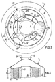
- FIG. 5 shows a device with two concentric sliding forms for loading three masses of concentric particulate material into the annular internal volume 5 defined between the interior 2 and exterior grids 3.
- the device comprises a rotating assembly 70, axially displaceable while advantageously suspended from the top of the container 1, from three overflow hoppers 71, 72, 73, connected by transverse arms 74 and provided with rolling or supporting bodies with low friction cooperating with the radial flanges 31 1 and 31 2 of two concentric tubular sliding forms 30 1 , 30 2 , separating the volumes of the three concentric adsorbent masses A, B, C.
- the dosing hoppers 71-73 fed by reserves rotating with the crew as in the embodiment of Figure 1, have lower discharge openings 81, 82, 83, respectively opening da ns the annular spaces between the internal formwork 31 2 and the internal grid 4, between the formwork 31 2 and 31 1 , and between the external formwork 31 1 and the external grid 3.
- the crew 70 is dismantled and extracted from the container 1 through the opening 20, then the upper volume above the masses A, B, C is at least partially occupied by one or more devices for restraining the upper parts of the masses AC, for example by a bladder 40 connectable to a source of pressurized gas.
- the problem main technique lies in the realization of at least two masses homogeneous particulate materials in the confined volume of the adsorber, more particularly when the masses are annular and concentric: the material levels must indeed be maintained particles in the receiving volume or in spreaders within narrow limits (the height of successive layers in the variants according to Figures 1 and 2, the height of the formwork sliding in the variants according to Figures 3 to 5, the height of the hopper of the spread). These heights are indeed necessarily limited due to the need to be able to remove the spill devices or spreaders from the container at the end of their filling or to abandon them in a volume in the top of the container without affecting the proper functioning of the installation.
- the spill / spreader devices can include a means for controlling the flow rate of the particulate material, typically upstream of the spreader device, for example racking with valves or lugs, as shown in 51 and 52 on the FIG. 1, means for measuring the level of the particulate material in the spreading hoppers, for example photocells like shown at 53 and 54 in Figure 2, or devices operating by reflection, in particular ultrasonic, as shown in 55 and 56 on the figure 5.
- FIG. 7 another alternative embodiment is shown. of concentric annular beds in a concentric bed installation similar to the previous ones.
- tanks 17 and 18 of particulate materials and their rotary support 19, here of the gallows type arranged, here, outside the container 1, and each discharging through a pipe telescopic or flexible 15, 16, respectively, in the spaces delimited adjacent annulars, in the intermediate annular volume 5 between the perforated walls 2 and 3, by a ferrule forming sliding formwork 30.
- each conduit 16, respectively, 15 opens slightly below the upper end of the formwork 30 while being secured to the latter, in a removable manner, at 46.
- this volume fills until the end of the duct 15, 16 is flush with the mass of particulate material, thereby interrupting the filling said volume.
- conduits 15 and 16 extend through filling orifices 40 formed in the wall top of container 1 directly above annular space 5 and angularly distributed around the axis of the container 1, and openings 41, 42 formed in deflector plates 43 and 44 typically converging in V towards each other leaving an annular passage 45 at their apex and superiorly delimiting the active part of the annular beds A and B in guiding the fluid flows, in this zone, through the latter.
- the ferrule 30 When it arrives, at the end of the ascent, at the level of the deflector plates 43 and 44, the ferrule 30 is hoisted, in the example shown, through the annular space 45 between the opposite ends of these plates deflectors and remains permanently housed in the upper end of the container 1 in the configuration shown in dotted lines at the top of the right part of FIG. 7.
- the openings 41 and 42 in the plates 43 and 44 are closed, then reserves of particulate materials are poured by the shortened conduits 15 and 16 above the deflector plates 44, 43 while remaining separated by the ferrule 30 immobilized in its position high.
- the filling is completed by dumping the particulate materials directly through the orifices 40 on either side of the shell 30, after which conduits 15 and 16, reservoirs 17 and 18, and their support 19 are removed, the passages 40 closed and the container placed in condition operational.
- sliding formwork 30 has a bottom part 30A "transparent" to gases, typically in grill sandwiches, which does not disturb the achievement of an area frank interface between two adjoining beds.
- said lower screened part can remain embedded in the operational area of beds A and B, below the deflectors 43, 44.
- the deflectors can be removed, the "full" part top of the formwork 30, also embedded in the masses A and B forming obstacle and avoiding the passage of short circuits of fluid from the top of the beds.
- FIG. 9 which represents a container at the start of filling, another embodiment of vertical layers has been illustrated adjoining differentiated materials without separation grid according to the invention.
- the materials are poured, in synchronism, directly in the annular chambers below the filling orifices 40.
- These chambers are initially delimited by a ferrule 33 high determined, the upper edge of which is fixed to the roof of the container and, in permanently at their lower end by an annular bottom wall 34 sliding tightly along the internal retention grids 2 and external 3, being retained, during its descent, by cables 47.
- the bottom wall 34 is gradually lowered until it rests on the bottom structure of container 1, as shown in dotted lines on the part lower of FIG. 9.
- the adjacent bed strata formed on either side of the shell 33 "descend" gradually with the bottom 34 while being maintained contiguous and guided by grids 2 and 3.
- the shell 33 which extends to the upper level of the "passing" zones of the contention grids 2 and 3, acts as a baffle anti-bypass, like the formwork 30 of the embodiments of Figures 7 and 8.
- FIGS. 1 and 2 can be used to sequentially lay parallel ribbons in non-cylindrical vertical treatment plants, particularly for arrange a plurality of masses of adjacent particulate material of thin and with different particle sizes.
Landscapes
- Chemical & Material Sciences (AREA)
- Chemical Kinetics & Catalysis (AREA)
- Organic Chemistry (AREA)
- Analytical Chemistry (AREA)
- Engineering & Computer Science (AREA)
- General Chemical & Material Sciences (AREA)
- Oil, Petroleum & Natural Gas (AREA)
- Fluid Mechanics (AREA)
- Physics & Mathematics (AREA)
- Devices And Processes Conducted In The Presence Of Fluids And Solid Particles (AREA)
- Separation Of Gases By Adsorption (AREA)
- Drying Of Solid Materials (AREA)
- Filling Or Emptying Of Bunkers, Hoppers, And Tanks (AREA)
Claims (14)
- Vorrichtung zur Behandlung mindestens eines Fluids, umfassend mindestens einen Behälter (1), der im Betriebszustand eine ungefähr vertikale Vorzugsrichtung hat und mindestens einen nichtvertikalen Strömungsabschnitt für Fluide hat, der durch zumindest zwei aneinandergrenzende, in dem Gehäuse angeordnete Massen (A, B, C) aus unterschiedlichem Teilchen- oder Granulatmaterial führt, wobei zumindest zwei aneinandergrenzende Massen über eine ungefähr vertikale Übergangszone in unmittelbarem Kontakt stehen und jede Masse in Querrichtung eine maximale Ausdehnung hat, die größer als die vierfache horizontale Dicke ist.
- Vorrichtung nach Anspruch 1, dadurch gekennzeichnet, daß die Übergangszone mindestens einen ebenen Bereich aufweist.
- Vorrichtung nach Anspruch 2, dadurch gekennzeichnet, daß die Übergangszone eine prismatische Form hat.
- Vorrichtung nach Anspruch 1, dadurch gekennzeichnet, daß die Übergangszone mindestens einen gekrümmten Bereich umfaßt.
- Vorrichtung nach Anspruch 4, dadurch gekennzeichnet, daß die Übergangszone eine zylindrische Form hat.
- Vorrichtung nach einem der Ansprüche 1 bis 5, dadurch gekennzeichnet, daß die Massen (A, B, C) eine gemeinsame Symmetrieachse haben.
- Vorrichtung nach Anspruch 5 oder 6, dadurch gekennzeichnet, daß die Massen (A, B, C) konzentrisch sind.
- Vorrichtung nach einem der Ansprüche 1 bis 6, dadurch gekennzeichnet, daß das Teilchenmaterial von zumindest einer der Massen ein Adsorber für mindestens einen Bestandteil des Fluids ist.
- Verwendung einer Vorrichtung nach einem der Ansprüche 1 bis 8 zur Behandlung eines Luftstroms.
- Verfahren zum Einbringen von mindestens zwei aneinandergrenzenden Massen aus Teilchen- oder Granulatmaterial in einen Behälter einer Vorrichtung nach einem der Ansprüche 1 bis 8, umfassend den Schritt:a) gleichzeitiges Einbringen einer Lage aus mindestens zwei aneinandergrenzenden Materialschichten mit jeweils festgelegter Stärke.
- Verfahren nach Anspruch 10, dadurch gekennzeichnet, daß der Schritt a) mehrmals wiederholt wird, um einen Stapel aus aneinandergrenzenden Schichten mit ungefähr der gleichen Stärke zu bilden.
- Verfahren nach Anspruch 11, dadurch gekennzeichnet, daß die festgelegte Stärke durch die vertikalen Abmessungen einer Schüttvorrichtung bestimmt ist.
- Verfahren nach Anspruch 12, dadurch gekennzeichnet, daß die Schüttvorrichtung mindestens eine gleitende Schale (30) mit vertikalen Mantellinien und mindestens zwei Mittel (15, 16; 71, 72, 73) zum Entleeren von Material umfaßt, die beidseits der Schalung nahe an dem oberen Ende der letzteren münden und mit dieser vertikal verschiebbar sind.
- Verfahren nach Anspruch 12, dadurch gekennzeichnet, daß jedes Mittel zum Entleeren aus mindestens zwei Leitungen (15; 16) besteht, deren unteres Ende unterhalb des oberen Randes der gleitenden Schale (30) mündet.
Applications Claiming Priority (3)
| Application Number | Priority Date | Filing Date | Title |
|---|---|---|---|
| FR9414825A FR2727875B1 (fr) | 1994-12-09 | 1994-12-09 | Installation de traitement d'au moins un fluide, applications au traitement d'un flux d'air et procede de chargement d'une masse de materiau particulaire d'une telle installation |
| FR9414825 | 1994-12-09 | ||
| PCT/FR1995/001626 WO1996017678A1 (fr) | 1994-12-09 | 1995-12-07 | Installation de traitement d'au moins un fluide, applications au traitement d'un flux d'air et procede de chargement de masses de materiaux particulaires dans une telle installation |
Publications (3)
| Publication Number | Publication Date |
|---|---|
| EP0743877A1 EP0743877A1 (de) | 1996-11-27 |
| EP0743877B1 true EP0743877B1 (de) | 1998-08-19 |
| EP0743877B2 EP0743877B2 (de) | 2005-01-12 |
Family
ID=9469637
Family Applications (1)
| Application Number | Title | Priority Date | Filing Date |
|---|---|---|---|
| EP95942227A Expired - Lifetime EP0743877B2 (de) | 1994-12-09 | 1995-12-07 | Vorrichtung zur behandlung von mindestens einem fluid, anwendung zur behandlung von einem luftstrom und verfahren zur füllung von einer derartigen vorrichtung mit einer masse von körnigem material |
Country Status (11)
| Country | Link |
|---|---|
| EP (1) | EP0743877B2 (de) |
| JP (1) | JPH09508856A (de) |
| KR (1) | KR970701093A (de) |
| CN (1) | CN1079034C (de) |
| BR (1) | BR9506767A (de) |
| CA (1) | CA2182895A1 (de) |
| DE (1) | DE69504179T3 (de) |
| ES (1) | ES2122715T3 (de) |
| FR (1) | FR2727875B1 (de) |
| WO (1) | WO1996017678A1 (de) |
| ZA (1) | ZA9510454B (de) |
Families Citing this family (4)
| Publication number | Priority date | Publication date | Assignee | Title |
|---|---|---|---|---|
| US5836362A (en) * | 1997-07-15 | 1998-11-17 | Praxair Technology, Inc. | Multiple adsorbent loading method and apparatus for a radial flow vessel |
| DE102015002260A1 (de) * | 2015-02-25 | 2016-08-25 | Linde Aktiengesellschaft | Verfahren zum Herstellen eines horizontal durchströmten Adsorbers und Trennwandmodul zur Verwendung in diesem Verfahren |
| CA3061684A1 (en) * | 2017-06-02 | 2018-12-06 | Casale Sa | Reactor with a catalytic bed |
| US10576455B2 (en) * | 2018-03-22 | 2020-03-03 | Air Products And Chemicals, Inc. | Particle loading method and apparatus for a radial flow vessel |
Family Cites Families (8)
| Publication number | Priority date | Publication date | Assignee | Title |
|---|---|---|---|---|
| FR2541588B1 (fr) † | 1983-02-28 | 1985-07-05 | Air Liquide | Recipient et installation d'epuration par adsorption |
| IN166220B (de) * | 1984-12-07 | 1990-03-31 | Chevron Res | |
| US5296202A (en) * | 1984-12-07 | 1994-03-22 | Chevron Research And Technology Co. | Apparatus for uniformly loading particulate material into cylindrical beds |
| JPH04141227A (ja) * | 1990-10-03 | 1992-05-14 | Nagaoka Kinmo Kk | ラジアルフロー式触媒充填塔における触媒保持方法および装置 |
| FR2667800B1 (fr) † | 1990-10-11 | 1992-12-04 | Air Liquide | Procede de separation par adsorption, et adsorbeur. |
| FR2668131B1 (fr) * | 1990-10-22 | 1993-01-29 | Inst Francais Du Petrole | Appareillage pour le remplissage d'un recipient par un produit solide divise. |
| JP3004446B2 (ja) * | 1992-02-17 | 2000-01-31 | ソフタード工業株式会社 | 反応塔および反応塔の触媒充填方法 |
| US5324159A (en) * | 1992-10-02 | 1994-06-28 | Praxair Technology, Inc. | Particle loader |
-
1994
- 1994-12-09 FR FR9414825A patent/FR2727875B1/fr not_active Expired - Fee Related
-
1995
- 1995-12-07 CN CN95191550A patent/CN1079034C/zh not_active Expired - Fee Related
- 1995-12-07 CA CA002182895A patent/CA2182895A1/en not_active Abandoned
- 1995-12-07 DE DE69504179T patent/DE69504179T3/de not_active Expired - Fee Related
- 1995-12-07 EP EP95942227A patent/EP0743877B2/de not_active Expired - Lifetime
- 1995-12-07 KR KR1019960704304A patent/KR970701093A/ko not_active Ceased
- 1995-12-07 WO PCT/FR1995/001626 patent/WO1996017678A1/fr not_active Ceased
- 1995-12-07 JP JP8517377A patent/JPH09508856A/ja active Pending
- 1995-12-07 ES ES95942227T patent/ES2122715T3/es not_active Expired - Lifetime
- 1995-12-07 BR BR9506767A patent/BR9506767A/pt not_active IP Right Cessation
- 1995-12-08 ZA ZA9510454A patent/ZA9510454B/xx unknown
Also Published As
| Publication number | Publication date |
|---|---|
| FR2727875A1 (fr) | 1996-06-14 |
| CN1140421A (zh) | 1997-01-15 |
| ZA9510454B (en) | 1996-11-25 |
| DE69504179T3 (de) | 2005-09-29 |
| BR9506767A (pt) | 1997-10-07 |
| EP0743877B2 (de) | 2005-01-12 |
| DE69504179T2 (de) | 1999-05-12 |
| CA2182895A1 (en) | 1996-06-13 |
| ES2122715T3 (es) | 1998-12-16 |
| WO1996017678A1 (fr) | 1996-06-13 |
| JPH09508856A (ja) | 1997-09-09 |
| DE69504179D1 (de) | 1998-09-24 |
| EP0743877A1 (de) | 1996-11-27 |
| FR2727875B1 (fr) | 1997-03-21 |
| KR970701093A (ko) | 1997-03-17 |
| CN1079034C (zh) | 2002-02-13 |
Similar Documents
| Publication | Publication Date | Title |
|---|---|---|
| US6302162B2 (en) | Installation for the treatment of at least one fluid, by passage through two adjacent masses of material | |
| EP0116246B1 (de) | Behälterfülleinrichtung mit Feststoffpartikeln | |
| EP3087031B1 (de) | Ammoniakkonverter mit rohrförmiger innenwand | |
| KR19990013799A (ko) | 반경 방향 흐름 용기에 다중 흡착제를 적재하기 위한 방법 및 장치 | |
| EP2370202B1 (de) | Vorrichtung zum laden von festen teilchen in eine kammer | |
| EP2689834B1 (de) | Reaktor zur kontinuierlichen Regeneration eines Katalysators mit Gasmischungs- und Gasverteilungsgehäuse in der Oxychlorierungszone | |
| CA2819809C (fr) | Dispositif de remplissage d'un recipient avec des particules solides comportant un diaphragme | |
| EP0743877B1 (de) | Vorrichtung zur behandlung von mindestens einem fluid, anwendung zur behandlung von einem luftstrom und verfahren zur füllung von einer derartigen vorrichtung mit einer masse von körnigem material | |
| FR2488519A1 (fr) | Systeme de filtrage modulaire | |
| EP1032464B1 (de) | Flüssigkeitsverteiler für nicht senkrechte destillationskolonne und damit ausgerüstete destillationskolonne | |
| FR2995798A1 (fr) | Reacteur de regeneration en continu de catalyseur avec des moyens deflecteurs pour devier l'ecoulement du catalyseur dans la zone d'oxychloration | |
| CA3020940A1 (fr) | Panier amovible pour reacteur catalytique | |
| EP0319368A1 (de) | Einspritzgerät für eine Kohlenwasserstoffladung in einem Reaktor | |
| EP0274309A1 (de) | Feuerlöschbehälter für brennende Flüssigkeiten | |
| EP3672719B1 (de) | Bewegliche vorrichtung zum füllen von katalytischen reaktorkammern | |
| CA2816938A1 (fr) | Dispositif allege de chargement de particules solides | |
| FR2588194A1 (fr) | Adsorbeur a lit adsorbant incline pour traiter des melanges gazeux | |
| FR2993793A1 (fr) | Reacteur de regeneration en continu de catalyseur avec caisson perfore pour melanger et distribuer des gaz dans la zone d'oxychloration | |
| EP3820601A1 (de) | Vorrichtung zur abgabe eines fluids, wobei die vorrichtung in einem reaktor mit festem katalysatorbett angeordnet sein kann | |
| EP4114802A1 (de) | Vorrichtung zum anaeroben abbau von organischem material | |
| FR2535374A1 (fr) | Silo pour produits en vrac | |
| FR2696727A1 (fr) | Installation de transfert en milieu contrôlé, de produits fragiles sous forme unitaire et transportés en vrac. | |
| FR2489718A1 (fr) | Tamis tournants pour separer les solides des liquides | |
| BE419746A (de) | ||
| CH351898A (fr) | Dispositif de transport de matière finement divisée par fluidisation, destiné au transport horizontal ou incliné |
Legal Events
| Date | Code | Title | Description |
|---|---|---|---|
| PUAI | Public reference made under article 153(3) epc to a published international application that has entered the european phase |
Free format text: ORIGINAL CODE: 0009012 |
|
| AK | Designated contracting states |
Kind code of ref document: A1 Designated state(s): BE DE ES FR GB IT NL SE |
|
| 17P | Request for examination filed |
Effective date: 19961213 |
|
| 17Q | First examination report despatched |
Effective date: 19970814 |
|
| GRAG | Despatch of communication of intention to grant |
Free format text: ORIGINAL CODE: EPIDOS AGRA |
|
| GRAG | Despatch of communication of intention to grant |
Free format text: ORIGINAL CODE: EPIDOS AGRA |
|
| GRAH | Despatch of communication of intention to grant a patent |
Free format text: ORIGINAL CODE: EPIDOS IGRA |
|
| GRAH | Despatch of communication of intention to grant a patent |
Free format text: ORIGINAL CODE: EPIDOS IGRA |
|
| GRAA | (expected) grant |
Free format text: ORIGINAL CODE: 0009210 |
|
| AK | Designated contracting states |
Kind code of ref document: B1 Designated state(s): BE DE ES FR GB IT NL SE |
|
| REF | Corresponds to: |
Ref document number: 69504179 Country of ref document: DE Date of ref document: 19980924 |
|
| GBT | Gb: translation of ep patent filed (gb section 77(6)(a)/1977) |
Effective date: 19981104 |
|
| REG | Reference to a national code |
Ref country code: ES Ref legal event code: FG2A Ref document number: 2122715 Country of ref document: ES Kind code of ref document: T3 |
|
| PLBQ | Unpublished change to opponent data |
Free format text: ORIGINAL CODE: EPIDOS OPPO |
|
| PLBI | Opposition filed |
Free format text: ORIGINAL CODE: 0009260 |
|
| PLBF | Reply of patent proprietor to notice(s) of opposition |
Free format text: ORIGINAL CODE: EPIDOS OBSO |
|
| 26 | Opposition filed |
Opponent name: PRAXAIR, INC. Effective date: 19990519 |
|
| PLBF | Reply of patent proprietor to notice(s) of opposition |
Free format text: ORIGINAL CODE: EPIDOS OBSO |
|
| RDAH | Patent revoked |
Free format text: ORIGINAL CODE: EPIDOS REVO |
|
| APAC | Appeal dossier modified |
Free format text: ORIGINAL CODE: EPIDOS NOAPO |
|
| APAC | Appeal dossier modified |
Free format text: ORIGINAL CODE: EPIDOS NOAPO |
|
| APAE | Appeal reference modified |
Free format text: ORIGINAL CODE: EPIDOS REFNO |
|
| REG | Reference to a national code |
Ref country code: GB Ref legal event code: IF02 |
|
| RAP2 | Party data changed (patent owner data changed or rights of a patent transferred) |
Owner name: L'AIR LIQUIDE, S.A. A DIRECTOIRE ET CONSEIL DE SUR |
|
| NLT2 | Nl: modifications (of names), taken from the european patent patent bulletin |
Owner name: L'AIR LIQUIDE, S.A. A DIRECTOIRE ET CONSEIL DE SUR |
|
| NLT1 | Nl: modifications of names registered in virtue of documents presented to the patent office pursuant to art. 16 a, paragraph 1 |
Owner name: L'AIR LIQUIDE, S.A. A DIRECTOIR ET CONSEIL DE SURV |
|
| PGFP | Annual fee paid to national office [announced via postgrant information from national office to epo] |
Ref country code: SE Payment date: 20021121 Year of fee payment: 8 Ref country code: NL Payment date: 20021121 Year of fee payment: 8 |
|
| PGFP | Annual fee paid to national office [announced via postgrant information from national office to epo] |
Ref country code: ES Payment date: 20021211 Year of fee payment: 8 |
|
| PGFP | Annual fee paid to national office [announced via postgrant information from national office to epo] |
Ref country code: BE Payment date: 20030106 Year of fee payment: 8 |
|
| PG25 | Lapsed in a contracting state [announced via postgrant information from national office to epo] |
Ref country code: SE Free format text: LAPSE BECAUSE OF NON-PAYMENT OF DUE FEES Effective date: 20031208 |
|
| PG25 | Lapsed in a contracting state [announced via postgrant information from national office to epo] |
Ref country code: ES Free format text: LAPSE BECAUSE OF NON-PAYMENT OF DUE FEES Effective date: 20031209 |
|
| PG25 | Lapsed in a contracting state [announced via postgrant information from national office to epo] |
Ref country code: BE Free format text: LAPSE BECAUSE OF NON-PAYMENT OF DUE FEES Effective date: 20031231 |
|
| PLBP | Opposition withdrawn |
Free format text: ORIGINAL CODE: 0009264 |
|
| APBU | Appeal procedure closed |
Free format text: ORIGINAL CODE: EPIDOSNNOA9O |
|
| BERE | Be: lapsed |
Owner name: S.A. L'*AIR LIQUIDE POUR L'ETUDE ET L'EXPLOITATION Effective date: 20031231 |
|
| PG25 | Lapsed in a contracting state [announced via postgrant information from national office to epo] |
Ref country code: NL Free format text: LAPSE BECAUSE OF NON-PAYMENT OF DUE FEES Effective date: 20040701 |
|
| EUG | Se: european patent has lapsed | ||
| NLV4 | Nl: lapsed or anulled due to non-payment of the annual fee |
Effective date: 20040701 |
|
| PUAH | Patent maintained in amended form |
Free format text: ORIGINAL CODE: 0009272 |
|
| STAA | Information on the status of an ep patent application or granted ep patent |
Free format text: STATUS: PATENT MAINTAINED AS AMENDED |
|
| 27A | Patent maintained in amended form |
Effective date: 20050112 |
|
| AK | Designated contracting states |
Kind code of ref document: B2 Designated state(s): BE DE ES FR GB IT NL SE |
|
| REG | Reference to a national code |
Ref country code: ES Ref legal event code: FD2A Effective date: 20031209 |
|
| GBTA | Gb: translation of amended ep patent filed (gb section 77(6)(b)/1977) | ||
| APAH | Appeal reference modified |
Free format text: ORIGINAL CODE: EPIDOSCREFNO |
|
| PGFP | Annual fee paid to national office [announced via postgrant information from national office to epo] |
Ref country code: FR Payment date: 20051110 Year of fee payment: 11 |
|
| PGFP | Annual fee paid to national office [announced via postgrant information from national office to epo] |
Ref country code: GB Payment date: 20051114 Year of fee payment: 11 |
|
| PGFP | Annual fee paid to national office [announced via postgrant information from national office to epo] |
Ref country code: DE Payment date: 20051117 Year of fee payment: 11 |
|
| PGFP | Annual fee paid to national office [announced via postgrant information from national office to epo] |
Ref country code: IT Payment date: 20061231 Year of fee payment: 12 |
|
| PG25 | Lapsed in a contracting state [announced via postgrant information from national office to epo] |
Ref country code: DE Free format text: LAPSE BECAUSE OF NON-PAYMENT OF DUE FEES Effective date: 20070703 |
|
| GBPC | Gb: european patent ceased through non-payment of renewal fee |
Effective date: 20061207 |
|
| REG | Reference to a national code |
Ref country code: FR Ref legal event code: ST Effective date: 20070831 |
|
| PG25 | Lapsed in a contracting state [announced via postgrant information from national office to epo] |
Ref country code: GB Free format text: LAPSE BECAUSE OF NON-PAYMENT OF DUE FEES Effective date: 20061207 |
|
| PG25 | Lapsed in a contracting state [announced via postgrant information from national office to epo] |
Ref country code: FR Free format text: LAPSE BECAUSE OF NON-PAYMENT OF DUE FEES Effective date: 20070102 |
|
| PG25 | Lapsed in a contracting state [announced via postgrant information from national office to epo] |
Ref country code: IT Free format text: LAPSE BECAUSE OF NON-PAYMENT OF DUE FEES Effective date: 20071207 |