EP0744120A1 - Verfahren und Vorrichtung um Gemüsse zu Ernten und zu Bündeln - Google Patents
Verfahren und Vorrichtung um Gemüsse zu Ernten und zu Bündeln Download PDFInfo
- Publication number
- EP0744120A1 EP0744120A1 EP96201497A EP96201497A EP0744120A1 EP 0744120 A1 EP0744120 A1 EP 0744120A1 EP 96201497 A EP96201497 A EP 96201497A EP 96201497 A EP96201497 A EP 96201497A EP 0744120 A1 EP0744120 A1 EP 0744120A1
- Authority
- EP
- European Patent Office
- Prior art keywords
- products
- tying
- bunching
- bunch
- lifting
- Prior art date
- Legal status (The legal status is an assumption and is not a legal conclusion. Google has not performed a legal analysis and makes no representation as to the accuracy of the status listed.)
- Granted
Links
- 238000000034 method Methods 0.000 title claims abstract description 12
- 238000003306 harvesting Methods 0.000 title claims abstract description 7
- 230000000452 restraining effect Effects 0.000 claims description 22
- 241000196324 Embryophyta Species 0.000 description 35
- 241000220259 Raphanus Species 0.000 description 7
- 235000006140 Raphanus sativus var sativus Nutrition 0.000 description 3
- 230000001419 dependent effect Effects 0.000 description 2
- 238000009434 installation Methods 0.000 description 2
- 238000010276 construction Methods 0.000 description 1
- 230000003111 delayed effect Effects 0.000 description 1
- 230000003287 optical effect Effects 0.000 description 1
- 238000000926 separation method Methods 0.000 description 1
Images



Classifications
-
- A—HUMAN NECESSITIES
- A01—AGRICULTURE; FORESTRY; ANIMAL HUSBANDRY; HUNTING; TRAPPING; FISHING
- A01D—HARVESTING; MOWING
- A01D31/00—Other digging harvesters
Definitions
- the invention relates to a method for harvesting and bunching agricultural and/or market garden produce, comprising of successively lifting the products out of the ground, holding on their haulm and bringing together into a bunch a determined number of products and tying together the haulm of the bunch of products.
- Such a method is known as "bunching" of for instance radishes.
- the radish plants which each consist of a tuber growing in the ground and a haulm protruding above the ground, are uprooted, picked up and collected, whereafter the thus collected radish plants are bunched into a cluster by tying together the haulm thereof with a cord or elastic.
- This "bunching" of radish is heavy, unpleasant and time-consuming work since radish plants are relatively small and are placed close together. Finding sufficient manpower is therefore difficult, all the more so as the cultivation of radish takes little time (about three weeks), particularly in the summer, and these bunching operations must therefore be performed frequently.
- the wage costs involved herein moreover contribute to the relatively high cost price of the product.
- the invention therefore has for its object to provide a method of the above described type wherein these difficulties do not occur.
- This is achieved according to the invention in that at least the bringing together and tying together of the products takes place mechanically. Bunching is hereby greatly simplified and speeded up, so that the cost price of a bunch is reduced and the temporary use each time of large numbers of workers can be prevented.
- the invention also has for its object to provide an apparatus for performing the above described method.
- Such an apparatus is provided according to the invention with means for successively lifting products out of the ground, means connected to the lifting means for bringing together a determined number of lifted products into a bunch and means for tying together the thus brought together bunch of products.
- Preferred embodiments of the apparatus according to the invention form the subject-matter of the dependent claims 5-21.
- the invention further relates to lifting means, disentangling means, selection means, bunching means, tying means and a closing and pushing member for use in an apparatus of the above described type.
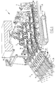
- An apparatus 1 for mechanically harvesting and bunching agricultural and/or market garden produce, such as for instance radish plants, comprises means 2 for successively lifting the plants 21 out of the ground 26, means 27 for reversing the lifted plants 21, means 28 for selecting the reversed plants 21, means 3 for bringing together a determined number of plants 21 into a bunch 29 and means 4 for tying together the thus formed bunch 29.
- the lifting means 2 comprise lifting knives 31 movable under the plants 21 through the ground 26 and guide plates 5 connected thereto.
- the raised plants 21 are received between parallel endless clamping belts 6 which each move along a set of guide rollers 7,8,9,10,11.
- the axes of guide rollers 9 herein lie transversely of the axes of the preceding and following guide rollers 7,8 respectively 10,11, whereby the clamping belts 6 are tilted on their longitudinal axis and the plants 21 are turned over (fig. 2).
- the lifting means are arranged in a sub-frame 32 which is pivotally connected by means of a pivot connection 33 to the main frame 34 of the apparatus.
- Sub-frame 32 can herein be moved up and downward relative to main frame 34 by means of a hoist installation 35.
- the movement of sub-frame 32 is controlled by an optical sensor (not shown) which detects the course of the bed with plants 21.
- the plants 21 with their tubers 22 pointing upward and their haulm 23 pointing downward are transferred to the selection means 28 formed by parallel endless clamping belts 12.
- the mutual distance of the belts 12 herein determines the minimum size of the selected plants.
- the belts 12 are herein adjustable in transverse direction of each other.
- the reversing rollers 36 of belts 12 are arranged for this purpose on rotatable shafts 37 which in turn are bearing mounted in blocks 38 which are slidable in transverse direction along a guide beam 39 (fig. 4).
- Shafts 37 of mutually adjacent selection paths alternately take a relatively short and a relatively long form, whereby the selection paths are situated at different heights in frame 34 (fig.
- each selection path is arranged on the drive shafts 37 of each selection path.
- the selection belts 12 and conveyor belts 19 are herein driven jointly by a continuous chain 41 which runs in a zigzag path over chain wheels 42 arranged on the top of shafts 37.
- the plants 21 can be separated before selection.
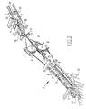
- disentangling means 58 (fig. 8) which are formed by the selection belts 12, which carry the tubers 22, and haulm transporting ropes 59 and 62.
- the distance between haulm transporting ropes 59, 62 respectively and the tuber transporting belts or selection belts 12 herein increases as seen in the transporting direction as a result of the fact that the haulm ropes 59, 62 enclose an angle ⁇ with the selection belt 12.
- the haulm ropes 59 and 62 are herein arranged in stepwise manner in a frame part 66 which is arranged on the front side of the apparatus.
- Each rope 59 is rotatable on two reversing rollers 60, 61, while ropes 62 are rotatable on reversing rollers 63 and 65 and an interposed guide roller 64.
- the forward reversing roller 63 of rope 62 is herein mounted on a common shaft with the rear reversing roller 61 of haulm rope 59, while the rear reversing roller 65 of the upper haulm rope 62 is arranged at the height of the reversing roller 36 of selection belt 12.
- the haulm of each plant 21 is thus clamped between the adjacently located ropes 59 and carried along in the transporting direction.
- the ropes 59 herein move at a higher or lower speed than the selection belts 12, whereby a further additional force is exerted on product 21. Due to this additional force and the fact that the distance between the haulm rope 59 and the selection belt 12 increases, the product 21 with its tuber 22 is tensioned tightly on selection belt 12. Products 21 of which the haulm 23 is mutually entangled are hereby pulled apart, while undersize tubers 22 are moreover pulled through between the selection belts 12 and removed.
- the disentangling means 58 take a double-action form with a lower haulm rope 59 and an upper haulm rope 62, although it will be apparent that more or fewer ropes can also be applied.
- the plants are subsequently guided past a counting means 14, for instance an electronic eye, whereafter they are held back by a restraining member, for instance an arm 15, until a determined, preset number of plants has passed the counting means 14.
- the restraining arm 15, which is arranged on an endless belt 16, is then moved out of the transport path of plants 12, whereby they can move further to the tying means 4.
- the following restraining arm 15 is simultaneously placed in the transport path.
- the arm 15 is herein not only movable with the belt 16 but is also slidable in the direction transversely of the belt 16 to the position 15'.
- arm 15 is arranged on two extending members 46 which are received for sliding in a block 47 and which are biased to the extended position by means of a spring 48.
- On the upper side one of the arms is provided with a roller 59 which runs along a guide track 60 connected to the frame 34 of the apparatus, whereby retraction and subsequent extension of the restraining arms 15 is controlled.
- the arm 15 thus skims over the leading plants of the following group before it is placed into the transport path.
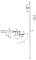
- a single restraining arm 15 is arranged per transport path (fig. 6), which arm can execute a combined pivoting and sliding movement as according to arrows R and L.
- the arm 15 is herein suspended in similar manner as in the embodiment shown in fig. 3. Under the influence of a pneumatic lift cylinder 45 the arm 15 can be retracted counter to the force of spring 48 or be extended under the influence of the spring action, while in addition the whole arm construction can be pivoted round an axis 44 by means of a pneumatic rotating cylinder 43.
- the restraining arm 15 can hereby be pivoted out of the path as according to arrow R, then be retracted by means of cylinder 45, pivoted back by cylinder 43 and finally moved back again into the transport path.
- the group of plants released by restraining arm 15 is carried to the tying means 4 by parallel belts 19 movable along guide rollers 20 and there collected in a practically circular receiving space 24 of a movable discharge member 30. Due to the continuous feed of plants 21 the plants of the group are pressed together in this receiving space to a practically circular bunch 29 which is then tied together with a cord or elastic by a tying member. The discharge member 30 is then pivoted on a transverse pivot shaft 25, whereby the bunch 29 falls out of the receiving space 24 onto the ground 26.
- the discharge member 30 is arranged not pivotally but slidably in the line of the transport path.
- the member 30, which once again has a circle segment-like receiving space 24, is provided for this purpose with fixing points 49 with which it is suspended from a frame movable parallel to the transport path by a pneumatic cylinder.
- the discharge member 30 is herein slidable in stepwise manner in order to prevent damage to the plants for tying together.
- the stepwise sliding movement of discharge member 30 is herein controlled by the counting means 14 which also actuates restraining arm 15.
- a slidable and pivotable pushing member 51 which comprises an arm 56 which is fixed onto an L-shaped head 55 which is in turn fixed to the outer end of a piston 54.
- Piston 54 is received in a cylinder 52 which is connected to the frame via a pivot connection 53.
- the operation of the discharge member is as follows: In the starting position (fig. 7a) the discharge member is situated in its retracted position directly behind the transport path. When now the counting means has detected a first group of for instance 5 or 6 plants, the restraining arm 15 is activated, whereby the whole of this group is allowed through. At that moment the cylinder of the discharge member is also activated, whereby it is moved a step to the rear (fig. 7b) and space is created to receive the first group of plants. The restraining member 15 is now kept in its retracted position whereby a flow of plants is allowed through.
- the counting means 14 counts the number of passing plants and at regular intervals, for instance each time 5 plants have passed, sends a signal to the cylinder of discharge member 30 which is then shifted a step at a time (fig. 7c and 7d).
- a step could optionally be performed per passing plant but this hardly gives a better result in practice.
- the restraining member is re-placed into the transport path and the pushing member 51 is activated with a slight delay.
- the piston 54 is herein extended from cylinder 52 and the head 55 rotated on its fixing points 57 by exerting a tensile force, whereby the arm 56 presses together the tubers (fig. 7e).
- the tying device is then activated, whereby a wire or elastic is wound and fastened round the bunch, whereafter the discharge member is moved to its furthest end position and the bunch released (fig. 7f).
- the bunch can herein fall onto a conveyor belt (not shown) whereby it is carried to a crate.
- a crate can also be arranged directly beneath discharge member 30.
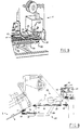
- the pushing member 51 is combined with a closing member 68 which extends in transverse direction over both conveyor belts 19.
- the combined closing and pushing member is once again embodied in the form of a cylinder 52 in which a piston 54 is slidable which is provided on its outer end with the actual pushing element 56 in the form of a pushing slide.
- the closing member 68 is herein fixed to the cylinder housing 52.
- Cylinder housing 52 is connected for pivoting on a lying shaft 53 to a part 67 of the frame.
- the pushing element 56 has the purpose of pushing together the tubers 22 prior to tying together, whereby a compact bunch is formed.
- the closing member 68 serves herein to prevent products, which may possibly still be present between the transporting ropes 19 and which somehow or other have been delayed between the restraining arm 15 and the tying means, from still reaching the tying means at the precise moment that a tying operation is taking place there.
- the tying mechanism could hereby become jammed.
- the closing and pushing member is pivotable transversely of the plane of the transporting ropes 19 between the shown position in which closing member 68 extends over the transport path and closes it off, and an upward pivoted position in which the transport path is left clear.
- the closing and pushing member is therefore pivoted downward with some delay until the closing member 68 is situated in the transport path.
- the delay is herein chosen such that at the moment of downward pivoting during normal operation all products allowed through by restraining arm 15 should have reached the tying means. Only when the closing and pushing member has been pivoted downward and thus closes the transport path, is the pushing element 56 pressed outward by the piston 54 against the bunch of products for tying, whereafter the tying operation can take place.
- the different components described above can be assembled in a frame which is provided with a chassis 17, for instance a caterpillar chassis, and with a drive whereby it is independently mobile.
- the apparatus 1 is herein then further provided with control means 18 for controlling the operation of the different components.
- the control means 18 can be programmable and be formed for instance by a so-called PLC.
Landscapes
- Life Sciences & Earth Sciences (AREA)
- Environmental Sciences (AREA)
- Basic Packing Technique (AREA)
Applications Claiming Priority (4)
| Application Number | Priority Date | Filing Date | Title |
|---|---|---|---|
| NL1000441 | 1995-05-26 | ||
| NL1000441 | 1995-05-26 | ||
| NL1002136 | 1996-01-22 | ||
| NL1002136A NL1002136C2 (nl) | 1995-05-26 | 1996-01-22 | Werkwijze en inrichting voor het oogsten en bundelen van land- en/of tuinbouwprodukten. |
Publications (2)
| Publication Number | Publication Date |
|---|---|
| EP0744120A1 true EP0744120A1 (de) | 1996-11-27 |
| EP0744120B1 EP0744120B1 (de) | 2002-12-11 |
Family
ID=26642085
Family Applications (1)
| Application Number | Title | Priority Date | Filing Date |
|---|---|---|---|
| EP19960201497 Expired - Lifetime EP0744120B1 (de) | 1995-05-26 | 1996-05-28 | Verfahren und Vorrichtung um Gemüsse zu Ernten und zu Bündeln |
Country Status (3)
| Country | Link |
|---|---|
| EP (1) | EP0744120B1 (de) |
| DE (1) | DE69625275T2 (de) |
| NL (1) | NL1002136C2 (de) |
Cited By (5)
| Publication number | Priority date | Publication date | Assignee | Title |
|---|---|---|---|---|
| FR2778526A1 (fr) | 1998-05-18 | 1999-11-19 | Christian Daussan | Machine pour recolter et botteler des produits agricoles |
| DE102014011777A1 (de) | 2014-08-12 | 2016-02-18 | Rudolf Behr | Verfahren zur Detektierung von Schädlingen während des Ernteprozesses von im Boden wachsenden Kulturpflanzen, zum Beispiel von Radieschen |
| DE102014011776A1 (de) | 2014-08-12 | 2016-02-18 | Rudolf Behr | Vorrichtung zur Detektierung von Schädlingen während des Ernteprozesses von im Boden wachsenden Kulturpflanzen, zum Beispiel von Radieschen |
| EP3047737A1 (de) | 2015-01-23 | 2016-07-27 | Denis Abraham Quaak | Automatische maschine zum abschneiden der feinwurzeln unter der zwiebel einer pflanze, einschliesslich führungsfläche zur anpassung der schnitthöhe |
| CN106982593A (zh) * | 2017-04-21 | 2017-07-28 | 伍崇德 | 多行甘蔗立式收割机 |
Families Citing this family (1)
| Publication number | Priority date | Publication date | Assignee | Title |
|---|---|---|---|---|
| DE102013018013A1 (de) | 2013-11-29 | 2015-06-03 | Beat Hauenstein | Verfahren und Vorrichtung zum Bündeln von Pflanzen, Pflanzenteilen sowie Gegenständen aller Art |
Citations (4)
| Publication number | Priority date | Publication date | Assignee | Title |
|---|---|---|---|---|
| US2525018A (en) * | 1946-08-10 | 1950-10-10 | Melvin J Corwin | Vegetable harvester |
| FR2295692A1 (fr) * | 1974-12-23 | 1976-07-23 | Rath Karl | Procede pour la recolte de plantes herbacees ou ligneuses |
| FR2582468A1 (fr) * | 1985-05-28 | 1986-12-05 | Lovato Vito | Machine pour recolter des plantes en rang telles que l'ail |
| FR2594794A1 (fr) * | 1986-02-21 | 1987-08-28 | Guerin Claude | Dispositif permettant la mise en botte de legumes ou plantes de facon continue et automatique |
-
1996
- 1996-01-22 NL NL1002136A patent/NL1002136C2/xx not_active IP Right Cessation
- 1996-05-28 EP EP19960201497 patent/EP0744120B1/de not_active Expired - Lifetime
- 1996-05-28 DE DE1996625275 patent/DE69625275T2/de not_active Expired - Fee Related
Patent Citations (4)
| Publication number | Priority date | Publication date | Assignee | Title |
|---|---|---|---|---|
| US2525018A (en) * | 1946-08-10 | 1950-10-10 | Melvin J Corwin | Vegetable harvester |
| FR2295692A1 (fr) * | 1974-12-23 | 1976-07-23 | Rath Karl | Procede pour la recolte de plantes herbacees ou ligneuses |
| FR2582468A1 (fr) * | 1985-05-28 | 1986-12-05 | Lovato Vito | Machine pour recolter des plantes en rang telles que l'ail |
| FR2594794A1 (fr) * | 1986-02-21 | 1987-08-28 | Guerin Claude | Dispositif permettant la mise en botte de legumes ou plantes de facon continue et automatique |
Cited By (5)
| Publication number | Priority date | Publication date | Assignee | Title |
|---|---|---|---|---|
| FR2778526A1 (fr) | 1998-05-18 | 1999-11-19 | Christian Daussan | Machine pour recolter et botteler des produits agricoles |
| DE102014011777A1 (de) | 2014-08-12 | 2016-02-18 | Rudolf Behr | Verfahren zur Detektierung von Schädlingen während des Ernteprozesses von im Boden wachsenden Kulturpflanzen, zum Beispiel von Radieschen |
| DE102014011776A1 (de) | 2014-08-12 | 2016-02-18 | Rudolf Behr | Vorrichtung zur Detektierung von Schädlingen während des Ernteprozesses von im Boden wachsenden Kulturpflanzen, zum Beispiel von Radieschen |
| EP3047737A1 (de) | 2015-01-23 | 2016-07-27 | Denis Abraham Quaak | Automatische maschine zum abschneiden der feinwurzeln unter der zwiebel einer pflanze, einschliesslich führungsfläche zur anpassung der schnitthöhe |
| CN106982593A (zh) * | 2017-04-21 | 2017-07-28 | 伍崇德 | 多行甘蔗立式收割机 |
Also Published As
| Publication number | Publication date |
|---|---|
| NL1002136C2 (nl) | 1996-11-27 |
| EP0744120B1 (de) | 2002-12-11 |
| DE69625275D1 (de) | 2003-01-23 |
| DE69625275T2 (de) | 2004-01-29 |
Similar Documents
| Publication | Publication Date | Title |
|---|---|---|
| US5025992A (en) | Hay feeding apparatus | |
| BE1020227A3 (nl) | Opraapeenheid met beweegbaar windscherm. | |
| EP3170383B1 (de) | Machine und verfahren zum ernten von obst | |
| NO822826L (no) | Lessevogn for oppsamling og transport av straamateriale | |
| CN105409436A (zh) | 蔬菜有序收获机 | |
| EP0744120B1 (de) | Verfahren und Vorrichtung um Gemüsse zu Ernten und zu Bündeln | |
| EP2223585B1 (de) | Pflanzvorrichtung | |
| EP1222845B1 (de) | Verfahren zum Trennen eckiger Setzlinge, Gerät zum Ausführen des Verfahrens und Pflanzmaschine mit einem solchen Gerät zum Pflanzen von Setzlingen | |
| IES64895B2 (en) | A mushroom harvesting aid | |
| NL7906281A (nl) | Beweegbare oogstmachine. | |
| WO2011142660A1 (en) | Device for wrapping a foil round a bale of mowed material and combination thereof with a baler | |
| NL1010255C2 (nl) | Bollenplanter. | |
| JPH08289641A (ja) | 農産物収穫機 | |
| JP5470722B2 (ja) | 根菜類収穫機 | |
| JPH09295606A (ja) | 花茎結束装置 | |
| CN108432453A (zh) | 可移动半自动式蔬果采集车 | |
| US5901539A (en) | Tomato harvester, with devices for the automatic displacement of the harvest containers | |
| GB2224766A (en) | Litter/leaves collecting device | |
| JPH09207907A (ja) | 結束機 | |
| WO1999024333A1 (en) | Method and device for isolating products and weighing and counting system combined therewith | |
| NL2016879B1 (nl) | Inrichting voor het vormen van bossen van gewassen en binden ervan, in het bijzonder een bos of boeket van snijbloemen | |
| EP1062863A1 (de) | Vorrichtung und Verfahren zur Bearbeitung von zumindest einem mit Folie abgedeckten Spargeldamm | |
| JP3448014B2 (ja) | にら等の物品出荷調製装置 | |
| KR200361575Y1 (ko) | 자주식 볏짚수거·압축·절단장치 | |
| US3979888A (en) | Machine for cutting and harvesting graminaceous plants |
Legal Events
| Date | Code | Title | Description |
|---|---|---|---|
| PUAI | Public reference made under article 153(3) epc to a published international application that has entered the european phase |
Free format text: ORIGINAL CODE: 0009012 |
|
| AK | Designated contracting states |
Kind code of ref document: A1 Designated state(s): BE DE FR GB NL |
|
| RBV | Designated contracting states (corrected) |
Designated state(s): BE DE FR GB NL |
|
| 17P | Request for examination filed |
Effective date: 19970526 |
|
| 17Q | First examination report despatched |
Effective date: 20000126 |
|
| GRAG | Despatch of communication of intention to grant |
Free format text: ORIGINAL CODE: EPIDOS AGRA |
|
| GRAG | Despatch of communication of intention to grant |
Free format text: ORIGINAL CODE: EPIDOS AGRA |
|
| GRAH | Despatch of communication of intention to grant a patent |
Free format text: ORIGINAL CODE: EPIDOS IGRA |
|
| GRAH | Despatch of communication of intention to grant a patent |
Free format text: ORIGINAL CODE: EPIDOS IGRA |
|
| GRAA | (expected) grant |
Free format text: ORIGINAL CODE: 0009210 |
|
| AK | Designated contracting states |
Kind code of ref document: B1 Designated state(s): BE DE FR GB NL |
|
| REG | Reference to a national code |
Ref country code: GB Ref legal event code: FG4D |
|
| REF | Corresponds to: |
Ref document number: 69625275 Country of ref document: DE Date of ref document: 20030123 |
|
| ET | Fr: translation filed | ||
| PLBE | No opposition filed within time limit |
Free format text: ORIGINAL CODE: 0009261 |
|
| STAA | Information on the status of an ep patent application or granted ep patent |
Free format text: STATUS: NO OPPOSITION FILED WITHIN TIME LIMIT |
|
| 26N | No opposition filed |
Effective date: 20030912 |
|
| PGFP | Annual fee paid to national office [announced via postgrant information from national office to epo] |
Ref country code: NL Payment date: 20090529 Year of fee payment: 14 |
|
| PGFP | Annual fee paid to national office [announced via postgrant information from national office to epo] |
Ref country code: FR Payment date: 20090527 Year of fee payment: 14 Ref country code: DE Payment date: 20090528 Year of fee payment: 14 |
|
| PGFP | Annual fee paid to national office [announced via postgrant information from national office to epo] |
Ref country code: BE Payment date: 20090602 Year of fee payment: 14 |
|
| PGFP | Annual fee paid to national office [announced via postgrant information from national office to epo] |
Ref country code: GB Payment date: 20090529 Year of fee payment: 14 |
|
| BERE | Be: lapsed |
Owner name: *KOPPERT MACHINES B.V. Effective date: 20100531 |
|
| REG | Reference to a national code |
Ref country code: NL Ref legal event code: V1 Effective date: 20101201 |
|
| GBPC | Gb: european patent ceased through non-payment of renewal fee |
Effective date: 20100528 |
|
| REG | Reference to a national code |
Ref country code: FR Ref legal event code: ST Effective date: 20110131 |
|
| PG25 | Lapsed in a contracting state [announced via postgrant information from national office to epo] |
Ref country code: NL Free format text: LAPSE BECAUSE OF NON-PAYMENT OF DUE FEES Effective date: 20101201 Ref country code: BE Free format text: LAPSE BECAUSE OF NON-PAYMENT OF DUE FEES Effective date: 20100531 |
|
| PG25 | Lapsed in a contracting state [announced via postgrant information from national office to epo] |
Ref country code: DE Free format text: LAPSE BECAUSE OF NON-PAYMENT OF DUE FEES Effective date: 20101201 |
|
| PG25 | Lapsed in a contracting state [announced via postgrant information from national office to epo] |
Ref country code: FR Free format text: LAPSE BECAUSE OF NON-PAYMENT OF DUE FEES Effective date: 20100531 |
|
| PG25 | Lapsed in a contracting state [announced via postgrant information from national office to epo] |
Ref country code: GB Free format text: LAPSE BECAUSE OF NON-PAYMENT OF DUE FEES Effective date: 20100528 |