EP0744170A2 - Installation autonome de lavage oculaire - Google Patents
Installation autonome de lavage oculaire Download PDFInfo
- Publication number
- EP0744170A2 EP0744170A2 EP96108489A EP96108489A EP0744170A2 EP 0744170 A2 EP0744170 A2 EP 0744170A2 EP 96108489 A EP96108489 A EP 96108489A EP 96108489 A EP96108489 A EP 96108489A EP 0744170 A2 EP0744170 A2 EP 0744170A2
- Authority
- EP
- European Patent Office
- Prior art keywords
- eye wash
- nozzle
- housing
- wash fluid
- flexible container
- Prior art date
- Legal status (The legal status is an assumption and is not a legal conclusion. Google has not performed a legal analysis and makes no representation as to the accuracy of the status listed.)
- Granted
Links
- 239000012530 fluid Substances 0.000 claims abstract description 191
- 238000004891 communication Methods 0.000 claims abstract description 9
- 230000033001 locomotion Effects 0.000 claims description 11
- 230000004044 response Effects 0.000 claims description 5
- 238000003825 pressing Methods 0.000 claims 3
- 230000000903 blocking effect Effects 0.000 claims 2
- 238000012546 transfer Methods 0.000 abstract description 2
- 238000000034 method Methods 0.000 description 14
- 239000002699 waste material Substances 0.000 description 9
- 230000005484 gravity Effects 0.000 description 8
- 238000011010 flushing procedure Methods 0.000 description 6
- 230000007423 decrease Effects 0.000 description 5
- 230000004913 activation Effects 0.000 description 4
- 238000009434 installation Methods 0.000 description 4
- 239000007788 liquid Substances 0.000 description 4
- 230000007774 longterm Effects 0.000 description 4
- 210000002445 nipple Anatomy 0.000 description 4
- 239000007921 spray Substances 0.000 description 4
- 210000003128 head Anatomy 0.000 description 3
- 239000011087 paperboard Substances 0.000 description 3
- 241000894006 Bacteria Species 0.000 description 2
- 230000008901 benefit Effects 0.000 description 2
- 239000000356 contaminant Substances 0.000 description 2
- 230000008713 feedback mechanism Effects 0.000 description 2
- 239000003517 fume Substances 0.000 description 2
- 239000007789 gas Substances 0.000 description 2
- 230000036541 health Effects 0.000 description 2
- 238000010438 heat treatment Methods 0.000 description 2
- 239000000463 material Substances 0.000 description 2
- 230000013011 mating Effects 0.000 description 2
- 230000007246 mechanism Effects 0.000 description 2
- 238000012986 modification Methods 0.000 description 2
- 230000004048 modification Effects 0.000 description 2
- 239000004033 plastic Substances 0.000 description 2
- 229920003023 plastic Polymers 0.000 description 2
- 238000009428 plumbing Methods 0.000 description 2
- 230000008569 process Effects 0.000 description 2
- 239000011343 solid material Substances 0.000 description 2
- 239000000243 solution Substances 0.000 description 2
- XLYOFNOQVPJJNP-UHFFFAOYSA-N water Substances O XLYOFNOQVPJJNP-UHFFFAOYSA-N 0.000 description 2
- ZAMOUSCENKQFHK-UHFFFAOYSA-N Chlorine atom Chemical compound [Cl] ZAMOUSCENKQFHK-UHFFFAOYSA-N 0.000 description 1
- 229920000114 Corrugated plastic Polymers 0.000 description 1
- 239000004698 Polyethylene Substances 0.000 description 1
- FAPWRFPIFSIZLT-UHFFFAOYSA-M Sodium chloride Chemical compound [Na+].[Cl-] FAPWRFPIFSIZLT-UHFFFAOYSA-M 0.000 description 1
- 230000003213 activating effect Effects 0.000 description 1
- 239000000853 adhesive Substances 0.000 description 1
- 230000001070 adhesive effect Effects 0.000 description 1
- 238000005452 bending Methods 0.000 description 1
- 238000000071 blow moulding Methods 0.000 description 1
- 229910052801 chlorine Inorganic materials 0.000 description 1
- 239000000460 chlorine Substances 0.000 description 1
- 238000004140 cleaning Methods 0.000 description 1
- 238000010276 construction Methods 0.000 description 1
- 238000011109 contamination Methods 0.000 description 1
- 230000003247 decreasing effect Effects 0.000 description 1
- 230000000994 depressogenic effect Effects 0.000 description 1
- 239000000428 dust Substances 0.000 description 1
- 230000007613 environmental effect Effects 0.000 description 1
- 230000008014 freezing Effects 0.000 description 1
- 238000007710 freezing Methods 0.000 description 1
- 230000006870 function Effects 0.000 description 1
- 238000001746 injection moulding Methods 0.000 description 1
- JEIPFZHSYJVQDO-UHFFFAOYSA-N iron(III) oxide Inorganic materials O=[Fe]O[Fe]=O JEIPFZHSYJVQDO-UHFFFAOYSA-N 0.000 description 1
- 238000012423 maintenance Methods 0.000 description 1
- 244000005700 microbiome Species 0.000 description 1
- 239000000203 mixture Substances 0.000 description 1
- 239000002991 molded plastic Substances 0.000 description 1
- 238000010137 moulding (plastic) Methods 0.000 description 1
- 239000002245 particle Substances 0.000 description 1
- -1 polyethylene Polymers 0.000 description 1
- 229920000573 polyethylene Polymers 0.000 description 1
- 239000003755 preservative agent Substances 0.000 description 1
- 239000008213 purified water Substances 0.000 description 1
- 230000009467 reduction Effects 0.000 description 1
- 238000001175 rotational moulding Methods 0.000 description 1
- 238000000926 separation method Methods 0.000 description 1
- 239000011780 sodium chloride Substances 0.000 description 1
- 239000007787 solid Substances 0.000 description 1
- 239000000126 substance Substances 0.000 description 1
- 239000008399 tap water Substances 0.000 description 1
- 235000020679 tap water Nutrition 0.000 description 1
- 230000002747 voluntary effect Effects 0.000 description 1
- 239000002759 woven fabric Substances 0.000 description 1
Images


Classifications
-
- A—HUMAN NECESSITIES
- A61—MEDICAL OR VETERINARY SCIENCE; HYGIENE
- A61H—PHYSICAL THERAPY APPARATUS, e.g. DEVICES FOR LOCATING OR STIMULATING REFLEX POINTS IN THE BODY; ARTIFICIAL RESPIRATION; MASSAGE; BATHING DEVICES FOR SPECIAL THERAPEUTIC OR HYGIENIC PURPOSES OR SPECIFIC PARTS OF THE BODY
- A61H35/00—Baths for specific parts of the body
- A61H35/02—Baths for specific parts of the body for the eyes
Definitions
- the present invention generally relates to self-contained emergency eye wash stations. More particularly, the present invention relates to an emergency eye wash station which employs a unique feedback mechanism for maintaining a constant flow of eye wash fluid upon actuation of the eye wash station and which employs a self-contained delivery system for maintaining long-term stability of the eye wash fluid prior to actuation of the eye wash station.
- ANSI American National Standards Institute
- portable eye wash fountains should deliver no less than 0.4 gallons per minute (1.5 liters per minute) of eye wash fluid for a time period of 15 minutes.
- a drawback of the gravity-fed eye wash fountains of the type described above is that they contain fluid significantly in excess of the amount required for actual flushing to meet the ANSI standards because the rate of flow of wash fluid from the gravity-fed eye wash fountains decreases over time.
- the reason for this decrease in fluid flow rate over time is that the fluid head height in the reservoir decreases as the wash fluid is dispensed from the nozzles, thereby decreasing the amount of hydraulic pressure on the wash fluid over time. This reduction in hydraulic pressure over time causes a corresponding decrease in the fluid flow rate.
- the reservoirs of gravity-fed eye wash fountains must hold a sufficient amount of eye wash fluid that the fluid flow rate does not drop below 0.4 gallons per minute prior to 15 minutes from activation.
- a further drawback of gravity-fed portable eye wash fountains is they often waste much of the wash fluid in the reservoir (as much as 30 percent of the initial supply) because there is insufficient hydraulic pressure to force all of the wash fluid from the reservoir through the nozzles.
- the flow of wash fluid through the nozzles substantially stops after only a portion of the wash fluid in the reservoir has been dispensed from the nozzles.
- eye wash fountains typically must be removed from their operating position for draining of unused wash fluid, cleaning, and refilling with fresh wash fluid. Such removal of the eye wash fountains from their operating position is burdensome and time-consuming. When refilled and ready to be returned to their operating position, the units often weigh in excess of 130 pounds.
- the housing supports the flexible container and supports a nozzle in fluid communication with the flexible container.
- the nozzle dispenses the eye wash fluid from the flexible container.
- the housing includes a drain capturing the eye wash fluid dispensed from the nozzle.
- the reservoir collects the eye wash fluid captured by the drain, and the reservoir is slidably mounted to the housing.
- the platen is connected to the reservoir. The platen is slidably movable relative to the housing and is located immediately above the flexible container.
- the platen presses downward on the flexible container with a downward force proportional to a weight of the eye wash fluid collected in the reservoir.
- the transfer of the weight of the eye wash fluid collected in the reservoir to the platen maintains a constant flow of eye wash fluid dispensed from the nozzle.
- the emergency eye wash station employs a self-contained delivery system comprising a flexible container containing an eye wash fluid, a nozzle, a seal element, and an actuation element.
- the nozzle is in fluid communication with the container and is detachably connectable to a housing of the eye wash station.
- the nozzle includes an upper pressure plate and a lower nozzle body.
- the lower nozzle body forms an inlet for receiving the eye wash fluid from the container and forms a plurality in apertures in fluid communication with the inlet.
- the upper pressure plate is detachably linked to the lower nozzle body.
- the seal element is removably coupled to the nozzle.
- the seal element firmly secures the upper pressure plate to the lower nozzle body such that the upper pressure plate blocks the apertures formed in the lower nozzle body.
- the actuation element is coupled to the seal element.
- the self-contained delivery system is able to maintain long-term stability of the eye wash fluid.
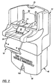
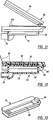
- FIGS. 1-7 illustrate a self-contained emergency eye wash station 10 used to dispense eye wash fluid contained in a pair of flexible containers.
- FIG. 1 is an exploded view depicting various components of the eye wash station 10, including a housing 12, a pair of platens 14, a cover 16, an actuation door 18, and a reservoir 46.
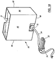
- the eye wash station 10 includes a self-contained eye wash fluid delivery system having a pair of identical delivery arrangements. One of these delivery arrangements is best shown in FIG. 18 prior to installation in the housing 12.
- the delivery arrangement in FIG. 18 includes a box 20, a flexible container 21 holding eye wash fluid, a nozzle 22, and a hose 24.
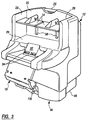
- a top of the housing 12 is provided with a handle 25 for mounting the eye wash station 10 to a vertical wall or mobile cart in an industrial work station, laboratory, or other location where workers are exposed to gaseous fumes, liquids or solid materials which can irritate or injure eyes upon contact therewith (FIGS. 2-4).
- the vertical wall or mobile cart is preferably provided with a conventional J-hook (not shown) supporting the handle 25.
- the top wall of the cover 16 is preferably curved to discourage individuals from laying loose items on the cover 16 which could contaminate the eye wash station 10 (FIGS. 1, 5, 6, and 7).
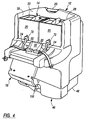
- the housing 12 supports the boxes 20 holding the respective flexible containers 21 and supports the nozzles 22 interconnected to the flexible containers 21 via the hoses 24 (FIG. 4).
- the housing 12 forms a rigid shelf 26 of sufficient width and depth to accommodate the pair of boxes 20 in side-by-side relation to one another (FIGS. 1, 3, and 4).
- the housing 12 provides side walls 28 to support the outer sides of the boxes 20 and a vertical rear wall 30 to support the back sides of the boxes 20 (FIG. 4).
- the side walls 28 are preferably spaced from each other by a distance only slightly greater than the combined width of the boxes 20 so that the boxes 20 snugly fit between the side walls 28. By virtue of this snug fit, the inner sides of the boxes 20 abut each another so that the boxes 20 provide each other with mutual support.
- the front wall of the cover 16 When the cover 16 is slidably mounted to the housing 12 as shown in FIGS. 6 and 7, the front wall of the cover 16 combines with the rear wall 30 (FIG. 4) of the housing 12 to support the respective front and back sides of the boxes 20.
- the front wall of the cover 16 and the rear wall 30 of the housing 12 are preferably spaced from each other by a distance only slightly greater than the depth of the boxes 20 so that the boxes 20 snugly fit between the front wall of the cover 16 and the rear wall 30 of the housing 12.
- each of the boxes 20 is supported on its four vertical sides and its bottom. As will become apparent, this support is desired during operation of the eye wash station 10 to prevent bulging of the boxes 20 as the platens 14 press downward on the flexible containers 21 within the respective boxes 20.
- the housing 12 includes a vertical front wall extending between the side walls 28. This front wall extends upwardly from the shelf 26 to the platens 14 when the platens 14 are in their upper position. Using this front wall, the housing 12 serves substantially the same support function as the boxes 20.
- the front wall may be hinged to the front edge of the shelf 26 to allow the front wall to be rotated downward to a horizontal position and permit front-loading of the flexible containers 21 into the housing 12.
- the platens 14 may be rotatable from their normal horizontal orientation to a vertical orientation to permit top-loading of the containers 21 into the housing 12.
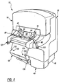
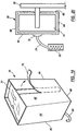
- the housing 12 includes a frontal nozzle mount 32 having a pair of elongated slots 34 formed therein (FIG. 1-3). These slots 34 cooperate with opposing grooves 36 (FIG. 8) formed in each nozzle 22 to slidably engage the nozzles 22 in the respective slots 34 (FIGS. 4, 5, and 7). This sliding engagement of the nozzles 22 in the respective slots 34 positively locates the nozzles 22 with respect to the housing 12.
- the width of each slot 34 is approximately the same as the width of each nozzle 22 in the region of the grooves 36 (FIG. 8) to create a fairly snug fit therebetween.
- the nozzles 22 are first positioned adjacent the outermost edges of the respective slots 34 (i.e., left edge of the left slot 34 and right edge of the right slot 34 in FIGS. 1-3). Next, with the opposing grooves 36 (FIG. 8) of each nozzle 22 aligned with the opposing elongated edges of each respective slot 34, the nozzles 22 are slid inwardly through the respective slots 34 with the opposing grooves 36 of each nozzle 22 slidably receiving the opposing elongated edges of each respective slot 34.
- the nozzles 22 dispense the eye wash fluid contained in the respective flexible containers 21 within the boxes 20 (FIG. 18).
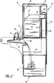
- the eye wash fluid dispensed from the nozzles 22 is captured in a basin 44 having a floor properly sloped to direct the eye wash fluid to a drain 38 (FIGS. 7 and 17).
- the drain 38 includes a pair of holes formed on opposite sides of the frontal nozzle mount 32. The eye wash fluid captured on the floor of the basin 44 flows backward around the nozzle mount 32 to the holes of the drain 38.
- the reservoir 46 includes a tank 48 of sufficient size to hold the volume of eye wash fluid contained in the flexible containers 21 within the boxes 20.
- the upper surface of the tank 48 forms a rectangular opening 50 to receive the eye wash fluid exiting the drain 38.
- the eye wash fluid flows through the holes of the drain 38 with sufficient velocity that the fluid is propelled into the rectangular opening 50 (FIG. 17).
- the drain 38 includes a pair of pipes extending from the respective drain holes to the rectangular opening 50 in the tank 48.
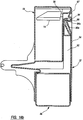
- the bottom of the housing 12 is completely open to permit the tank 48 to extend upward into the housing 12 (FIGS. 2-7 and 17).
- the housing 12 conceals a substantial portion of the tank 48 (FIG. 6).
- the tank 48 moves downward relative to the stationary housing 12 in response to the tank 48 collecting the eye wash fluid therein (FIG. 17).
- the tank 48 is substantially exposed beneath the housing 12.
- the eye wash station 10 When the eye wash station 10 is mounted to a vertical wall or mobile cart in an industrial work station, laboratory, or the like, the eye wash station 10 is mounted at such a height that the tank 48 will not contact the floor or ground prior to being substantially filled with the eye wash fluid.
- the lower surface of the tank 48 is preferably curved to encourage proper mounting of the eye wash station 10 to a vertical wall. With this curved lower surface, the eye wash station 10 will not remain upright if it is allowed to stand freely on the floor or ground.
- the transverse cross-section of the tank 48 is substantially identical in shape to the transverse cross-section of the lowermost portion of the housing 12 (FIGS. 1-7). Moreover, the transverse cross-section of the tank 48 is only slightly smaller in size than the transverse cross-section of the lowermost portion of the housing 12. Thus, a tight tolerance exists between the housing 12 and the tank 48.
- the reservoir 46 further includes a rear support 52 extending upward from a rear portion of the tank 48 (FIGS. 1 and 17). As best shown in FIG. 17, the rear support 52 extends into the housing 12 between the rear wall 30 and a second rear wall 54 parallel to the rear wall 30. The rear walls 30 and 54 define a narrow cavity in the housing 12 for receiving the rear support 52 of the reservoir 46. As the reservoir 46 moves vertically relative to the housing 12, the rear support 52 slides vertically through the cavity. To ensure smooth movement of the reservoir 46 relative to the housing 12, the width and thickness of the rear support 52 are only slight smaller than the corresponding dimensions of the cavity. In accordance with the vertical movement of the tank 48, the rear support 52 slides vertically downward through the cavity as the tank 48 collects the eye wash fluid therein.
- the platens 14 are located immediately above the flexible containers 21 (FIGS. 4, 17, and 20). As described below, the platens 14 are responsible for maintaining a constant flow of the eye wash fluid dispensed from the nozzles 22. The platens 14 press downward on the flexible containers 21 in the respective boxes 20 with a downward force proportional to a weight of the eye wash fluid collected in the reservoir 46. Therefore, the greater the volume of eye wash fluid in the reservoir 46, the greater the downward force that the platens 14 apply to the flexible containers 21.
- the weight of this collected eye wash fluid is essentially transferred by the reservoir 46 to the platens 14 (FIG. 17).
- the reservoir 46 pulls downward on the platens 14 with a force approximately equal to the combination of the weight of the reservoir 46 and the weight of the collected eye wash fluid. Since the platens 14 are located immediately above the flexible containers 21 within the respective boxes 20, pulling downward on the platens 14 causes the platens 14 to press downward on the flexible containers 21 with a force equivalent to the aforementioned weight combination. This downward force maintains a constant flow of the eye wash fluid from the nozzles 22.
- the reservoir 46 and the platens 14 serve as a feedback mechanism using the weight of the collected eye wash fluid to apply downward force to the flexible containers 21.
- the eye wash fluid delivery system Prior to using the eye wash station 10, the eye wash fluid delivery system is loaded into the housing 12.
- the delivery system includes a pair of identical delivery arrangements, one of which is best shown in FIG. 18.
- Each delivery arrangement includes the flexible container 21 within the box 20, the nozzle 22, and the flexible hose 24 interconnecting the nozzle 22 to the flexible container 21.
- Each of the foregoing components of the delivery arrangement is described in detail below.
- the box 20, shown in detail in FIGS. 18 and 19, contains the flexible container 21 substantially filed with eye wash fluid.
- the eye wash fluid is preferably a purified fluid such as a buffered isotonic saline solution, although it could be as simple as purified water.
- An exemplary solution is eye saline ® manufactured by Fendall Company of Arlington Heights, Illinois.
- the purified eye wash fluid may have a special composition directed toward certain types of hazards.
- the flexible container 21 is preferably a metallized MYLARTM bag including a layer of polyethylene.
- the box 20 is preferably composed of corrugated plastic or thick-walled corrugated paperboard.
- the lower portion of the front wall 60 of the box 20 forms a hole sized to accommodate an outlet fitment 72 (FIG. 18).
- One end of the flexible hose 24 is firmly connected to this outlet fitment 72.
- the other end of the flexible hose 24 is firmly connected to an inlet fitment 74 on the nozzle 22.
- the hose 24 has an inner diameter of approximately 0.38 inches (0.95 cm).
- the strap 92 is not adhered to the upper surface of the pressure plate 76 in the region beneath the shrink band 86.
- the manner in which this strap 92 is used to separate the upper pressure plate 76 from the lower nozzle body 78, and thereby permit eye wash fluid to be dispensed from the lower nozzle body 78 via the apertures 82, is described in detail below.
- This lower central portion is taken along a vertical plane of mirror symmetry passing through the center of the tank 48 and the centers of the respective basin 44 and nozzle mount 32 of the housing 12.
- the upper, laterally outward portion is taken along a vertical plane passing through one of the latches 94 and its associated catch 96.
- the cover 16 is preferably designed to automatically disengage each platen-release latch 94 from the associated catch 96 upon closure thereof.
- the cover 16 forms a downwardly extending rear tab 97.
- Mounting the cover 16 to the housing 12 causes the tab 97 to deflect the latch 94 clockwise until the edge 94a of the latch 94 no longer supports the edge 96a of the catch 96, thereby releasing the rear support 52 (FIG. 16c). Since the platens 14 are connected to the rear support 52, disengaging the rear support 52 releases the platens 14 from their upper position so that the platens 14 drop onto the flexible containers 21 within the respective boxes 20 (FIG. 4).
- buttons are mounted to the housing 12 and coupled to the respective latches 94. Prior to mounting the cover 16 to the housing 12, the buttons are depressed to disengage the latches 94 from the respective catches 96.
- the detachable fastening means includes male fasteners 101 attached to the ends of the straps 96 and holes 103 formed in the actuation door 18 slightly inward from the notches 100.
- the male fasteners 101 form barbs to firmly secure these fasteners within the respective holes 103.
- the length of the straps 92 is selected such that the straps 92 are sufficiently slack to avoid placing undue stress on the shrink bands 86, and yet are sufficiently taut to fit within the notches 100 formed in the opposing sides of the door 18 so that slippage is not a problem when the eye wash station 10 is activated.
- the eye wash station 10 is now ready for operation in the event of an emergency requiring a user to flush his or her eyes.
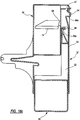
- the actuation door 18 serves as a dust cover protecting the nozzles 22 and basin 44 from contaminants in the environment.
- the user opens the actuation door 18 by grasping onto its integrally-formed handle 102 and pulling the actuation door 18 via the handle 102 to its open position (FIG. 7). Opening the actuation door 18 activates the flow of the eye wash fluid from the nozzles 22 by pulling the straps 92 relative to the respective nozzles 22. More specifically, opening the actuation door 18 pulls each strap 92 in a direction countering the force applied by the associated shrink band 86 to the nozzle 22 (FIGS. 8-10).
- each aperture 82 provides a separate stream of eye wash fluid.
- the user flushes his or her eyes by bending over and positioning his or her eyes over the dispensed streams of eye wash fluid.
- the left eye is flushed with the streams emitted from the left nozzle body, while the right eye is flushed with the streams emitted from the right nozzle body.
- the user While flushing his or her eyes, the user typically leans on the eye wash station 10 for balance and support by placing his or her elbows on right and left arms 105a, 105b (FIG. 7) of the housing 12.
- the user holds his or her eyes open with his or her fingers to permit flushing thereof.
- each nozzle body 78 To prevent the emitted streams from falling back on the apertures 82 in the nozzle bodies 78, the streams are emitted from the lower nozzle bodies 78 at a slight forward angle relative to the vertical direction (FIG. 17). In the preferred embodiment, this angle is approximately eight degrees relative to the vertical direction. Moreover, to minimize wicking between the multiple streams dispensed from each nozzle body 78, the upper surface of each nozzle body 78 forms an array of nipples or standoffs 104 (FIGS. 11 and 15). The apertures 82 extend through the respective nipples 104 so that the streams are emitted from the lower nozzles bodies 78 via the nipples 104.
- the nipples 104 extend approximately 0.063 inches (1.6 mm) above the flat portion of the upper surface of the associated nozzle body 78. Since the apertures 82 are arranged in an elongated array (FIGS. 14 and 15), the streams of eye wash fluid emitted from each nozzle body 78 form an elongated ribbon-like pattern. It has been found that this elongated pattern provides better coverage to the eyes of the user than nozzles having apertures arranged in a circular array.
- the flexible containers 21 contain a sufficient volume of the eye wash fluid so that the nozzles 22 deliver no less than 0.4 gallons per minute (1.5 liters per minute) of eye wash fluid for a time period of 15 minutes.
- the fluid flow rate is approximately 0.45 gallons per minute, and the flow rate does not fluctuate from this value until the flexible containers 21 substantially run out of the eye wash fluid.
- the eye wash station 10, including the size of the flexible containers 21 and the pressure applied by the platens 14, can be modified to achieve a different flow rate for a different time period in order to satisfy any changes in the standards for eye wash stations.
- the platens 14 move vertically downward from their upper position toward their lower position.
- the platens 14 are in their lower position and the emergency use of the eye wash station 10 has been completed.
- the tank 48 is preferably printed with such language as "UNIT DISCHARGED” or "UNIT DISCHARGED - SERVICE IMMEDIATELY" (FIGS. 1 and 2). This language is hidden by the housing 12 prior to use of the station 10 (FIG. 6), but is exposed following use of the station 10.
- the tank 48 is provided with an integral valve 106 at its lower end for draining the waste fluid from the tank 48 into a conventional waste container positioned beneath the tank 48 (FIGS. 1-7). Opening the valve 106 permits the waste fluid to empty into the waste container.
- the valve 106 may be a self-closing valve. If the valve 106 is self-closing, the service personnel must hold the valve 106 while draining the waste fluid from the tank 48.
- the valve 106 may be designed with a lever which only permits the tank 48 to be lifted upward into the housing 12 when the lever is in the closed position. When the valve 106 is in the open position, the lever interferes with the housing 12 when the service personnel attempt to use the tank 48 upward into the housing 12. When the valve 106 is in the closed position, the lever clears the housing 12 when the tank 48 is lifted upward.
- the cover 16 is slidably removed from the housing 12 to permit access to the interior of the housing 12.
- the tank 48 lifted upward into the housing 12 until the latches 94 engage the respective catches 96 in the rear support 52. Since the tank 48 is connected to the platens 14 via the rear support 52, lifting the tank 48 effectively moves the platens 14 from their lower position to their upper position. Engagement of the catches 96 by the respective latches 94 maintains the platens 14 in their upper position.
- the lower nozzle bodies 78 of the nozzles 22 are then slidably disengaged from their respective slots 34, and the straps 92 are disconnected from the actuation door 18 to detach the upper pressure plates 76 of the nozzles 22 from the door 18.
- a fresh (unused) eye wash fluid delivery system is loaded into the housing 12 (FIGS. 4-6). Since the procedure for loading the delivery system into the housing 12 is described above, it will not be repeated in detail herein. It suffices to state that new boxes 20 holding new flexible containers 21 containing fresh eye wash fluid are placed within the housing 12 on the shelf 26 beneath the respective platens 14, and new nozzles 22 are slidably mounted to the frontal nozzle mount 32. Next, the cover 16 is mounted to the housing 12 to disengage the latches 94 from the respective catches 96 and cause the platens 14 to drop onto the new flexible containers 21. Finally, the actuation door 18 is closed, and new straps 92 extending from the new nozzles 22 are fastened to the actuation door 18. The eye wash station 10 is now ready for emergency use.
- the eye wash station 10 is manufactured using conventional plastic molding techniques.
- the housing 12, the platens 14, the cover 16, and the actuation door 18 are composed of plastic and are manufactured using conventional rotational molding or blow molding techniques.
- the nozzles 22 are composed of molded plastic and are manufactured using conventional injection molding techniques.
- the straps 92 are preferably labelled with a batch identification number and an expiration date to provide a means for informing the user of the freshness of the eye wash fluid in the flexible containers 21.
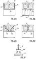
- FIG. 21b schematically depicts a gas cylinder-lifted support method where the extension springs 112 in FIG. 21a are replaced with gas cylinders 114 which force the shelf 108 upward so that the shelf 108 presses the flexible containers 21 against the stationary top wall 110.
- FIG. 21c schematically depicts a spring-lifted hinged shelf method where the flexible containers 21 sit on respective shelves 116 hingedly connected to respective opposing side walls 118.
- FIG. 22 Yet another technique for maintaining a constant fluid flow rate is schematically illustrated in FIG. 22.
- pressure is not applied to the flexible containers 21.
- a deformable flow restrictor 126 is connected in the fluid flow path between each flexible container 21 and the associated nozzle 22.
- the deformable flow restrictor 126 may be connected to the nozzle 22, and the hose 24 may, in turn, be connected to an input end of the deformable flow restrictor 126.
- the deformable flow restrictor 126 contains a flexible valve which gradually deforms (opens) as indicated by the arrows in FIG. 22.
- the self-contained delivery system depicted in FIG. 23 may be used as a stand alone eye wash system.
- the box 20 holding a fluid-filled flexible container is hung on a wall or in a vehicle using a hanging strap 128.
- the nozzle 22 is mounted to the box 20 using a retainer clip 130.
- the actuation strap 92 is affixed to the box by adhesive or the like.
- the stand alone system in FIG. 23 is preferably employed as a secondary eye wash station which would allow the user to quickly flush his or her eyes until he or she has access to a primary eye wash station, such as the eye wash station in FIG. 6.
- An advantage of the stand alone system in FIG. 23 is that it can be readily carried in a vehicle or to a remote site.
Landscapes
- Health & Medical Sciences (AREA)
- Ophthalmology & Optometry (AREA)
- Epidemiology (AREA)
- Pain & Pain Management (AREA)
- Physical Education & Sports Medicine (AREA)
- Rehabilitation Therapy (AREA)
- Life Sciences & Earth Sciences (AREA)
- Animal Behavior & Ethology (AREA)
- General Health & Medical Sciences (AREA)
- Public Health (AREA)
- Veterinary Medicine (AREA)
- Devices For Medical Bathing And Washing (AREA)
- Infusion, Injection, And Reservoir Apparatuses (AREA)
Priority Applications (2)
| Application Number | Priority Date | Filing Date | Title |
|---|---|---|---|
| EP05000620A EP1547569A2 (fr) | 1995-05-26 | 1996-05-28 | Système de distribution de fluide pour le lavage oculaire |
| EP01109792A EP1118317B1 (fr) | 1995-05-26 | 1996-05-28 | Système de distribution de fluide pour le lavage oculaire |
Applications Claiming Priority (2)
| Application Number | Priority Date | Filing Date | Title |
|---|---|---|---|
| US08/451,191 US5566406A (en) | 1995-05-26 | 1995-05-26 | Self-contained emergency eye wash station |
| US451191 | 1995-05-26 |
Related Child Applications (1)
| Application Number | Title | Priority Date | Filing Date |
|---|---|---|---|
| EP01109792A Division EP1118317B1 (fr) | 1995-05-26 | 1996-05-28 | Système de distribution de fluide pour le lavage oculaire |
Publications (3)
| Publication Number | Publication Date |
|---|---|
| EP0744170A2 true EP0744170A2 (fr) | 1996-11-27 |
| EP0744170A3 EP0744170A3 (fr) | 1997-08-20 |
| EP0744170B1 EP0744170B1 (fr) | 2002-07-31 |
Family
ID=23791177
Family Applications (3)
| Application Number | Title | Priority Date | Filing Date |
|---|---|---|---|
| EP01109792A Expired - Lifetime EP1118317B1 (fr) | 1995-05-26 | 1996-05-28 | Système de distribution de fluide pour le lavage oculaire |
| EP05000620A Withdrawn EP1547569A2 (fr) | 1995-05-26 | 1996-05-28 | Système de distribution de fluide pour le lavage oculaire |
| EP96108489A Expired - Lifetime EP0744170B1 (fr) | 1995-05-26 | 1996-05-28 | Installation autonome de lavage oculaire |
Family Applications Before (2)
| Application Number | Title | Priority Date | Filing Date |
|---|---|---|---|
| EP01109792A Expired - Lifetime EP1118317B1 (fr) | 1995-05-26 | 1996-05-28 | Système de distribution de fluide pour le lavage oculaire |
| EP05000620A Withdrawn EP1547569A2 (fr) | 1995-05-26 | 1996-05-28 | Système de distribution de fluide pour le lavage oculaire |
Country Status (4)
| Country | Link |
|---|---|
| US (3) | US5566406A (fr) |
| EP (3) | EP1118317B1 (fr) |
| CA (1) | CA2177094C (fr) |
| DE (2) | DE69622639T2 (fr) |
Families Citing this family (34)
| Publication number | Priority date | Publication date | Assignee | Title |
|---|---|---|---|---|
| US6296626B1 (en) | 1998-11-13 | 2001-10-02 | Bradley Fixtures Corporation | Eye wash station |
| USD438983S1 (en) | 1998-11-13 | 2001-03-13 | Bradley Corporation | Eye wash station |
| US6070279A (en) * | 1999-10-01 | 2000-06-06 | Fendall Company | Method and kit for retrofitting a plumbed eyewash station |
| US6520431B2 (en) | 2001-05-25 | 2003-02-18 | Speakman Company | Emergency eyewash apparatus |
| US7011652B1 (en) | 2002-12-18 | 2006-03-14 | Berke-Tec, Inc. | Eye wash station |
| US6976279B1 (en) | 2003-08-08 | 2005-12-20 | Berke-Tec, Inc. | Eye injury treatment station |
| US7181370B2 (en) * | 2003-08-26 | 2007-02-20 | Siemens Energy & Automation, Inc. | System and method for remotely obtaining and managing machine data |
| US7244246B2 (en) * | 2003-09-05 | 2007-07-17 | Bradley Fixtures Corporation | Eyewash system |
| US7254848B2 (en) * | 2004-04-01 | 2007-08-14 | Encon Safety Products, Inc. | Emergency eye wash system |
| USD529185S1 (en) * | 2004-11-16 | 2006-09-26 | Haws Drinking Faucet Company | Eyewash unit |
| US7278177B1 (en) | 2005-04-29 | 2007-10-09 | Ken Duffie | Emergency eye wash station |
| US20070089231A1 (en) * | 2005-10-24 | 2007-04-26 | Fendall, Inc. | Emergency eyewash station having a peircing mechanism to puncture a sealed fluid bladder |
| WO2007050525A1 (fr) * | 2005-10-24 | 2007-05-03 | Sperian Eye & Face Protection, Inc. | Poste de lavage oculaire d'urgence comprenant un systeme de collecte de dechets extensible a soufflets |
| WO2007050524A1 (fr) * | 2005-10-24 | 2007-05-03 | Sperian Eye & Face Protection, Inc. | Ensemble pompe pour douche oculaire d'urgence |
| WO2007050523A1 (fr) * | 2005-10-24 | 2007-05-03 | Sperian Eye & Face Protection, Inc. | Ensemble cartouche conçu pour un poste de lavage oculaire d'urgence autonome |
| US20070089234A1 (en) * | 2005-10-24 | 2007-04-26 | Fendall, Inc. | Emergency eyewash station having an integrated head rest |
| US20070108228A1 (en) * | 2005-11-15 | 2007-05-17 | Willam Kleyne | Method and apparatus for flushing eyes and skin |
| US8313472B2 (en) * | 2006-03-15 | 2012-11-20 | Sperian Eye & Face Protection, Inc. a Delaware corporation | Emergency eyewash station and dispensing structure therefor |
| GB2455684B (en) * | 2006-10-30 | 2011-11-16 | Bradley Fixtures Corp | Eyewash system |
| WO2008124451A1 (fr) * | 2007-04-05 | 2008-10-16 | Bradley Fixtures Corporation | Système de lavage oculaire |
| US8034036B2 (en) * | 2007-04-10 | 2011-10-11 | Tom Osborne | Portable eye flushing system and method |
| USD618342S1 (en) | 2007-10-29 | 2010-06-22 | Bradley Fixtures Corporation | Tank for eyewash system |
| AU2009249423B2 (en) | 2008-05-20 | 2014-02-13 | Haws Corporation | Emergency eyewash unit |
| USD612064S1 (en) * | 2008-06-06 | 2010-03-16 | Haws Corporation | Emergency eyewash unit |
| USD662220S1 (en) * | 2009-09-08 | 2012-06-19 | Bradley Fixtures Corporation | Sprayhead |
| USD662219S1 (en) * | 2009-09-08 | 2012-06-19 | Bradley Fixtures Corporation | Basin for wash system |
| USD662605S1 (en) * | 2009-09-08 | 2012-06-26 | Bradley Fixtures Corporation | Sprayhead |
| USD642698S1 (en) * | 2010-10-21 | 2011-08-02 | Haws Corporation | Faucet mounted eyewash unit |
| US8590751B2 (en) * | 2011-03-07 | 2013-11-26 | Gojo Industries, Inc. | Utility panel for a dispenser |
| US20140266716A1 (en) * | 2013-03-15 | 2014-09-18 | Honeywell International Inc. | Eyewash station with automatic expiration warning |
| US10882773B1 (en) | 2014-02-25 | 2021-01-05 | Waterfleet, LLC | Water purification system |
| US10115490B1 (en) | 2017-04-06 | 2018-10-30 | Mwd-Ip Holdings, Llc | Method for nuclear waste storage and monitoring |
| CN210124996U (zh) | 2018-12-29 | 2020-03-06 | 霍尼韦尔国际公司 | 移动式眼部清洗台 |
| WO2022165753A1 (fr) * | 2021-02-05 | 2022-08-11 | 中国科学院深圳先进技术研究院 | Appareil souple permettant d'ouvrir les paupières et son procédé |
Citations (3)
| Publication number | Priority date | Publication date | Assignee | Title |
|---|---|---|---|---|
| FR80792E (fr) | 1961-12-14 | 1963-06-14 | Commissariat Energie Atomique | Appareil pour le lavage des yeux |
| US4012798A (en) | 1975-09-29 | 1977-03-22 | Liautaud John R | Portable emergency eye wash fountain |
| US4363146A (en) | 1980-07-06 | 1982-12-14 | Liautaud John R | Eye wash fountain |
Family Cites Families (23)
| Publication number | Priority date | Publication date | Assignee | Title |
|---|---|---|---|---|
| US396708A (en) * | 1889-01-22 | payne | ||
| US289528A (en) * | 1883-12-04 | Goodneb | ||
| US852827A (en) * | 1906-11-17 | 1907-05-07 | Frank C Dorment | Eye massage apparatus and medicator combined. |
| US1759459A (en) * | 1927-05-02 | 1930-05-20 | James A Murdock | Dispensing top for bottled carbonated liquids |
| FR1281309A (fr) * | 1960-11-24 | 1962-01-12 | Boîte-support pour récipient de solutions médicamenteuses | |
| US3261355A (en) * | 1964-03-11 | 1966-07-19 | Burbig Henry | Aerated eye cup with air storage vessel |
| US3871554A (en) * | 1974-02-04 | 1975-03-18 | Sybron Corp | Eye wash station |
| US3963147A (en) * | 1975-01-08 | 1976-06-15 | The Raymond Lee Organization, Inc. | Dispenser for amorphous material |
| US4131115A (en) * | 1976-09-20 | 1978-12-26 | Peng Sung S | Eyelids-turning and eye-washing fixture |
| DE2744545A1 (de) * | 1977-10-04 | 1979-04-12 | Gerhard Beutel | Vorrichtung zur gezielten abgabe einer fluessigkeit aus einem behaelter |
| US4278089A (en) * | 1978-11-09 | 1981-07-14 | Howmedica, Inc. | Wound drainage device |
| US4632276A (en) * | 1983-12-30 | 1986-12-30 | Yukio Makino | Liquid dispensing device |
| US4798599A (en) * | 1984-01-03 | 1989-01-17 | George Thomas | Eye washing method and apparatus |
| SE451295B (sv) * | 1985-03-27 | 1987-09-28 | Fagersta El & Diesel Ab | Ogondusch |
| CA1272918A (fr) * | 1986-04-15 | 1990-08-21 | Paul Y. Wang | Dispositif de compression pour emballages souples de solutions aux fins de leur vidage a un rythme constant |
| US4939800A (en) * | 1987-06-19 | 1990-07-10 | Mckesson Corporation | Eye wash station |
| US4881283A (en) * | 1988-09-09 | 1989-11-21 | Liautaud John R | Self contained eye wash fountain |
| US4991742A (en) * | 1989-08-01 | 1991-02-12 | Chang Chin Fu | Automatic drip bottle set |
| US5030214A (en) * | 1990-11-01 | 1991-07-09 | Larry Spector | Ocular delivery system |
| CH680360A5 (fr) * | 1991-09-17 | 1992-08-14 | Supermatic Kunststoff Ag | |
| US5346132A (en) * | 1992-11-12 | 1994-09-13 | Gary S. Hahn | Mist generator |
| US5607410A (en) * | 1993-02-16 | 1997-03-04 | Branch; John D. | Vision directed eye wash |
| US5381567A (en) * | 1993-09-20 | 1995-01-17 | Encon Safety Products | Mobile emergency eyewash and body splash apparatus |
-
1995
- 1995-05-26 US US08/451,191 patent/US5566406A/en not_active Expired - Lifetime
-
1996
- 1996-05-22 CA CA002177094A patent/CA2177094C/fr not_active Expired - Lifetime
- 1996-05-28 EP EP01109792A patent/EP1118317B1/fr not_active Expired - Lifetime
- 1996-05-28 DE DE69622639T patent/DE69622639T2/de not_active Expired - Fee Related
- 1996-05-28 EP EP05000620A patent/EP1547569A2/fr not_active Withdrawn
- 1996-05-28 DE DE69635497T patent/DE69635497T2/de not_active Expired - Fee Related
- 1996-05-28 EP EP96108489A patent/EP0744170B1/fr not_active Expired - Lifetime
- 1996-05-30 US US08/655,764 patent/US5695124A/en not_active Expired - Lifetime
-
1997
- 1997-08-06 US US08/906,997 patent/US5850641A/en not_active Expired - Lifetime
Patent Citations (3)
| Publication number | Priority date | Publication date | Assignee | Title |
|---|---|---|---|---|
| FR80792E (fr) | 1961-12-14 | 1963-06-14 | Commissariat Energie Atomique | Appareil pour le lavage des yeux |
| US4012798A (en) | 1975-09-29 | 1977-03-22 | Liautaud John R | Portable emergency eye wash fountain |
| US4363146A (en) | 1980-07-06 | 1982-12-14 | Liautaud John R | Eye wash fountain |
Also Published As
| Publication number | Publication date |
|---|---|
| DE69622639T2 (de) | 2002-12-05 |
| US5695124A (en) | 1997-12-09 |
| EP0744170B1 (fr) | 2002-07-31 |
| EP0744170A3 (fr) | 1997-08-20 |
| US5850641A (en) | 1998-12-22 |
| DE69635497T2 (de) | 2006-07-27 |
| DE69635497D1 (de) | 2005-12-29 |
| CA2177094A1 (fr) | 1996-11-27 |
| EP1547569A2 (fr) | 2005-06-29 |
| DE69622639D1 (de) | 2002-09-05 |
| CA2177094C (fr) | 2007-11-06 |
| EP1118317A2 (fr) | 2001-07-25 |
| EP1118317A3 (fr) | 2003-11-26 |
| US5566406A (en) | 1996-10-22 |
| EP1118317B1 (fr) | 2005-11-23 |
Similar Documents
| Publication | Publication Date | Title |
|---|---|---|
| US5566406A (en) | Self-contained emergency eye wash station | |
| US7588168B2 (en) | Combination dispenser for carrying product dispensers | |
| US6070279A (en) | Method and kit for retrofitting a plumbed eyewash station | |
| EP1292484B1 (fr) | Appareil mobile conforme aux reglements de securite | |
| MXPA97002302A (es) | Sistema de llenado de solucion quimica | |
| MXPA05013033A (es) | Conjunto de trapeador y carro. | |
| MX2008015699A (es) | Sistema surtiudor de productos multiples. | |
| US9259139B2 (en) | Sanitary foot sprayer for dry powder plants | |
| CA2571661C (fr) | Poste autonome de rincage oculaire d'urgence | |
| US8313472B2 (en) | Emergency eyewash station and dispensing structure therefor | |
| AU2003262890A1 (en) | Procedure and device for cleaning floors with flat cleaning mops | |
| US7278177B1 (en) | Emergency eye wash station | |
| US6719216B2 (en) | Handle strap | |
| EP1945088B1 (fr) | Manche de balai a franges avec reservoir integre et poste de remplissage | |
| KR20190009545A (ko) | 직수 방식 토출과 스프레이 방식 분사가 가능토록 하는 다단 마개 | |
| Jonkoniec | Spacecraft utensil/hand cleansing fixture | |
| EP0295963A2 (fr) | Installation de lavage oculaire | |
| US20050183742A1 (en) | Procedure and device for cleaning floors with flat cleaning mops | |
| MXPA04003364A (es) | Soporte de pared para ensamble de abastecimiento. |
Legal Events
| Date | Code | Title | Description |
|---|---|---|---|
| PUAI | Public reference made under article 153(3) epc to a published international application that has entered the european phase |
Free format text: ORIGINAL CODE: 0009012 |
|
| AK | Designated contracting states |
Kind code of ref document: A2 Designated state(s): DE FR GB IT |
|
| PUAL | Search report despatched |
Free format text: ORIGINAL CODE: 0009013 |
|
| AK | Designated contracting states |
Kind code of ref document: A3 Designated state(s): DE FR GB IT |
|
| 17P | Request for examination filed |
Effective date: 19980212 |
|
| 17Q | First examination report despatched |
Effective date: 20000921 |
|
| GRAG | Despatch of communication of intention to grant |
Free format text: ORIGINAL CODE: EPIDOS AGRA |
|
| GRAG | Despatch of communication of intention to grant |
Free format text: ORIGINAL CODE: EPIDOS AGRA |
|
| GRAH | Despatch of communication of intention to grant a patent |
Free format text: ORIGINAL CODE: EPIDOS IGRA |
|
| GRAH | Despatch of communication of intention to grant a patent |
Free format text: ORIGINAL CODE: EPIDOS IGRA |
|
| GRAA | (expected) grant |
Free format text: ORIGINAL CODE: 0009210 |
|
| AK | Designated contracting states |
Kind code of ref document: B1 Designated state(s): DE FR GB IT |
|
| REG | Reference to a national code |
Ref country code: GB Ref legal event code: FG4D |
|
| REF | Corresponds to: |
Ref document number: 69622639 Country of ref document: DE Date of ref document: 20020905 |
|
| ET | Fr: translation filed | ||
| PLBE | No opposition filed within time limit |
Free format text: ORIGINAL CODE: 0009261 |
|
| STAA | Information on the status of an ep patent application or granted ep patent |
Free format text: STATUS: NO OPPOSITION FILED WITHIN TIME LIMIT |
|
| 26N | No opposition filed |
Effective date: 20030506 |
|
| PGFP | Annual fee paid to national office [announced via postgrant information from national office to epo] |
Ref country code: DE Payment date: 20070524 Year of fee payment: 12 |
|
| PGFP | Annual fee paid to national office [announced via postgrant information from national office to epo] |
Ref country code: GB Payment date: 20070523 Year of fee payment: 12 |
|
| PGFP | Annual fee paid to national office [announced via postgrant information from national office to epo] |
Ref country code: IT Payment date: 20070528 Year of fee payment: 12 |
|
| PGFP | Annual fee paid to national office [announced via postgrant information from national office to epo] |
Ref country code: FR Payment date: 20070510 Year of fee payment: 12 |
|
| GBPC | Gb: european patent ceased through non-payment of renewal fee |
Effective date: 20080528 |
|
| REG | Reference to a national code |
Ref country code: FR Ref legal event code: ST Effective date: 20090119 |
|
| PG25 | Lapsed in a contracting state [announced via postgrant information from national office to epo] |
Ref country code: FR Free format text: LAPSE BECAUSE OF NON-PAYMENT OF DUE FEES Effective date: 20080602 Ref country code: DE Free format text: LAPSE BECAUSE OF NON-PAYMENT OF DUE FEES Effective date: 20081202 |
|
| PG25 | Lapsed in a contracting state [announced via postgrant information from national office to epo] |
Ref country code: GB Free format text: LAPSE BECAUSE OF NON-PAYMENT OF DUE FEES Effective date: 20080528 |
|
| PG25 | Lapsed in a contracting state [announced via postgrant information from national office to epo] |
Ref country code: IT Free format text: LAPSE BECAUSE OF NON-PAYMENT OF DUE FEES Effective date: 20080528 |