EP0744228A1 - Bloc pour courber et balancer dans une cage quarto pour laminer des feuillards ou des tÔles - Google Patents
Bloc pour courber et balancer dans une cage quarto pour laminer des feuillards ou des tÔles Download PDFInfo
- Publication number
- EP0744228A1 EP0744228A1 EP96107529A EP96107529A EP0744228A1 EP 0744228 A1 EP0744228 A1 EP 0744228A1 EP 96107529 A EP96107529 A EP 96107529A EP 96107529 A EP96107529 A EP 96107529A EP 0744228 A1 EP0744228 A1 EP 0744228A1
- Authority
- EP
- European Patent Office
- Prior art keywords
- curvature
- block
- rolls
- balancing
- jack means
- Prior art date
- Legal status (The legal status is an assumption and is not a legal conclusion. Google has not performed a legal analysis and makes no representation as to the accuracy of the status listed.)
- Granted
Links
- 238000005096 rolling process Methods 0.000 title claims abstract description 33
- 238000000034 method Methods 0.000 title 1
- 239000002775 capsule Substances 0.000 description 4
- 238000010586 diagram Methods 0.000 description 2
- 230000001419 dependent effect Effects 0.000 description 1
- 230000000694 effects Effects 0.000 description 1
- 230000008030 elimination Effects 0.000 description 1
- 238000003379 elimination reaction Methods 0.000 description 1
- 238000004519 manufacturing process Methods 0.000 description 1
- 238000004904 shortening Methods 0.000 description 1
Images
Classifications
-
- B—PERFORMING OPERATIONS; TRANSPORTING
- B21—MECHANICAL METAL-WORKING WITHOUT ESSENTIALLY REMOVING MATERIAL; PUNCHING METAL
- B21B—ROLLING OF METAL
- B21B29/00—Counter-pressure devices acting on rolls to inhibit deflection of same under load, e.g. backing rolls ; Roll bending devices, e.g. hydraulic actuators acting on roll shaft ends
-
- B—PERFORMING OPERATIONS; TRANSPORTING
- B21—MECHANICAL METAL-WORKING WITHOUT ESSENTIALLY REMOVING MATERIAL; PUNCHING METAL
- B21B—ROLLING OF METAL
- B21B13/00—Metal-rolling stands, i.e. an assembly composed of a stand frame, rolls, and accessories
-
- B—PERFORMING OPERATIONS; TRANSPORTING
- B21—MECHANICAL METAL-WORKING WITHOUT ESSENTIALLY REMOVING MATERIAL; PUNCHING METAL
- B21B—ROLLING OF METAL
- B21B31/00—Rolling stand structures; Mounting, adjusting, or interchanging rolls, roll mountings, or stand frames
- B21B31/16—Adjusting or positioning rolls
- B21B31/20—Adjusting or positioning rolls by moving rolls perpendicularly to roll axis
- B21B31/203—Balancing rolls
-
- B—PERFORMING OPERATIONS; TRANSPORTING
- B21—MECHANICAL METAL-WORKING WITHOUT ESSENTIALLY REMOVING MATERIAL; PUNCHING METAL
- B21B—ROLLING OF METAL
- B21B13/00—Metal-rolling stands, i.e. an assembly composed of a stand frame, rolls, and accessories
- B21B13/001—Convertible or tiltable stands, e.g. from duo to universal stands, from horizontal to vertical stands
-
- B—PERFORMING OPERATIONS; TRANSPORTING
- B21—MECHANICAL METAL-WORKING WITHOUT ESSENTIALLY REMOVING MATERIAL; PUNCHING METAL
- B21B—ROLLING OF METAL
- B21B2203/00—Auxiliary arrangements, devices or methods in combination with rolling mills or rolling methods
- B21B2203/36—Spacers
-
- B—PERFORMING OPERATIONS; TRANSPORTING
- B21—MECHANICAL METAL-WORKING WITHOUT ESSENTIALLY REMOVING MATERIAL; PUNCHING METAL
- B21B—ROLLING OF METAL
- B21B31/00—Rolling stand structures; Mounting, adjusting, or interchanging rolls, roll mountings, or stand frames
- B21B31/08—Interchanging rolls, roll mountings, or stand frames, e.g. using C-hooks; Replacing roll chocks on roll shafts
- B21B31/10—Interchanging rolls, roll mountings, or stand frames, e.g. using C-hooks; Replacing roll chocks on roll shafts by horizontally displacing, i.e. horizontal roll changing
-
- B—PERFORMING OPERATIONS; TRANSPORTING
- B21—MECHANICAL METAL-WORKING WITHOUT ESSENTIALLY REMOVING MATERIAL; PUNCHING METAL
- B21B—ROLLING OF METAL
- B21B31/00—Rolling stand structures; Mounting, adjusting, or interchanging rolls, roll mountings, or stand frames
- B21B31/16—Adjusting or positioning rolls
- B21B31/18—Adjusting or positioning rolls by moving rolls axially
Definitions
- This invention concerns a block to provide curvature and balancing for four-high rolling mill stands to produce strip or plate, as set forth in the main claim.
- the curvature and balancing block according to the invention is employed to create in relation to the rolling plane a pre-curvature of the rolling rolls inwards, namely towards the other roll " IN “ or outwards " OUT “ so as to oppose or enhance the deflections generated in the processing rolls during the rolling operations.
- the field of rolling covers the problem caused by the deflections generated by the rolling force in the processing rolls.
- four-high rolling mill stands which comprise two back-up rolls, an upper back-up roll and a lower back-up roll respectively, which act on the respective processing rolls and through which is applied the rolling pressure against the processing rolls.
- US-A-4,038,857 discloses curvature and balancing blocks which are arranged as counterparts and laterally on one side and the other of the chocks of the rolls and which have a substantially E-shaped cross-section and with which there cooperate the chocks associated with the ends of the processing rolls and back-up rolls; these blocks support a plurality of jacks to provide curvature and balancing.
- This E-shaped block defines with its three ribs, namely an upper, intermediate and lower rib respectively, two spaces in which are positioned respective lateral extensions provided in the chocks of the processing rolls.
- E-shaped blocks also include upper and lower supporting jacks with which act on the chocks of the back-up rolls.
- the jacks to provide curvature and balancing are arranged respectively on the lower surface of the upper rib, on the upper surface of the lower rib and on the lower and upper surfaces of the central rib; the purpose is to act from above or from below, according to the requirements, on the lateral extensions of the chocks positioned within the spaces defined by the ribs of the E-shaped block.
- a pre-curvature of the axis of the processing roll is generated upwards or downwards in relation to the rolling plane according to the particular rolling requirements.
- E-shaped blocks entail a problem linked to the fact that, when the outer jacks, namely the jacks associated with the lower surface of the upper rib and with the upper surface of the lower rib, are actuated to determine an " OUT " curvature of the processing rolls, these upper and lower ribs of the E-shaped block tend, under the action exerted by the outer jacks, to yield and to be deformed outwards resiliently.
- This axial traversing has the effect that the force of feedback arising from the action of the curvature jacks may be offset from the axis of the bearings supporting the processing rolls associated with the relative chocks, thus causing problems of the working life of the bearings of the processing rolls.
- the wear on the processing rolls where E-shaped blocks are involved is limited by the geometric configuration of the E-shaped block and of the chocks of the processing rolls.
- FR-A-1.363.766 too discloses a device substantially like that described above with the difference that the curvature and balancing block is an integral part of the supporting structure of the rolling mill stand and is substantially C-shaped; on the chock of the lower processing roll there acts only a jack from above, and only an " IN " curvature can be generated in that lower processing roll.
- JP-A-59-056910 discloses a curvature and balancing block which includes jacks that can generate only an " IN " curvature in the processing rolls.
- the purpose of this invention is to provide a curvature and balancing block fitted to a four-high rolling mill stand for the processing of strip or plate so as to generate the required pre-curvature in the processing rolls.
- the block according to the invention always ensures a correct balance and eliminates the unbalanced forces acting on the bearings within the chocks of the processing rolls.
- the rolling mill stands to which the curvature and balancing blocks according to the invention are applied include advantageously hydraulic actuator capsules positioned between the chock of the lower or upper back-up roll and the relative housing, these capsules being actuated to control the rolls in position.
- the curvature and balancing block according to the invention makes it possible to ensure that the feedback exerted by the chock is substantially always positioned on the centreline of the bearing of the processing roll.
- the thrust exerted by the balancing jacks is substantially on the same axis as the hydraulic actuator capsules associated with the housings, irrespective of the axial position of the processing rolls, thus ensuring a correct balancing and an excellent stability of the rolling mill stand.
- the block according to the invention makes possible the elimination of the resilient deflections of the upper and lower ribs of the blocks of the state of the art, these deflections being due to unbalanced thrusts generated by the curvature jacks when an " OUT " curvature is imparted to the processing rolls.
- the block according to the invention includes, at least on the outer surface of the upper or lower rib of the block, compensation jack means which have the function of opposing the unbalanced thrusts acting on that rib and of eliminating the deflection.
- the curvature and balancing block has a C-shaped conformation and is associated with the ends of a processing roll, whether that roll be the upper or lower processing roll.
- the C-shaped block includes curvature jack means arranged on the inner surface of the respective upper and lower ribs and on the outer surface of the rib associated with the other processing roll, while the other rib includes on its outer surface compensation jack means.
- the curvature and balancing block according to the invention has an E-shaped conformation, in which the respective upper and lower ribs include compensation jack means associated with the respective outer surfaces of those ribs.
- the compensation jack means associated respectively with the upper surface of the upper rib and the lower surface of the lower rib have the task of balancing the thrust generated by the curvature jack means when an " OUT " curvature is imparted to the processing rolls.
- the compensation jack means prevent the respective upper and lower ribs of the E-shaped block from being stressed with high values.
- the jack means consist of two parallel actuators spaced apart along the axis of the processing rolls.
- two-positional attachment means are included in the curvature and balancing block according to the invention.
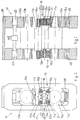
- the reference number 10 denotes generally a curvature and balancing block associated with processing rolls 11 of a rolling mill stand 12 which comprises a pair of processing rolls 11, each of which cooperates with a respective back-up roll 13.
- the block 10 according to the invention is fitted to the rolling mill stand 12 so as to determine a desired curvature in the processing rolls 11 and to balance the thrusts due to the rolling.
- the rolling mill stand 12 comprises a pair of processing rolls 11, namely a lower roll 11a and an upper roll 11b respectively, each of which is in contact with a respective back-up roll 13a and 13b; the ends of those rolls 11, 13 are associated with respective chocks 15, 16 associated in turn with the uprights of the housings 17 of the rolling mill stand 12.
- the block 10 has a C-shaped transverse conformation and is applied to only one processing roll, which in this case is the lower processing roll 11a.
- the C-shaped block 10 includes a lower rib 18a and an upper rib 18b defining between then an intermediate space 19 with which there cooperates a chock 15a associated with the lower processing roll 11a.
- the upper rib 18b includes on its upper side first jack means 20a to provide curvature of the upper processing roll 11b and on its lower side second jack means 20b to provide curvature of the lower processing roll 11a.
- the lower rib 18a includes on its upper side third jack means 20c to provide curvature of the lower processing roll 11a and on its lower side compensation jack means 21.
- the first curvature jack means 20a and the second curvature jack means 20b are actuated to impart an " IN " curvature to the processing rolls 11a, 11b; the actions of these curvature jack means 20a, 20b balance and cancel each other.
- the processing rolls 11, when they have been correctly curved, are controlled in position by acting on hydraulic actuator capsules 23, which adjust the rolling pass and are associated with an upper cross-member of the housing 24 of the rolling mill stand 12.
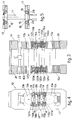
- Figs.3 and 4 show a second E-shaped form of embodiment of a block 110 providing curvature and balancing.
- This E-shaped block 110 includes three ribs 118, namely a lower rib 118a, an upper rib 118b and a central rib 118c respectively, which, two by two, define respective lower 119a and upper 119b spaces.
- supporting jacks 14 which cooperate with chocks 16a, 16b of the respective back-up rolls 13a, 13b.
- the E-shaped block 110 includes jack means 120 to provide curvature and jack means 121 to provide compensation.
- the central rib 118c includes on its two surfaces the curvature jack means 120a and 120b which are actuated to impart an " IN " curvature to the two processing rolls 11a, 11b; these two actions cancel each other and thus keep the block 110 substantially undeformed and balanced.
- the inner surfaces of the lower rib 118a and of the upper rib 118b include respective curvature jack means 120c and 120d, which are actuated to impart an " OUT " curvature to the processing rolls 11; the actions of these curvature jack means 120c and 120d are balanced by compensation jack means 121a, 121b associated respectively with the lower surface of the lower rib 118a and with the upper surface of the upper rib 118b.
- each of the curvature jack means 20, 120 and of the compensation jack means 21, 121 comprises a pair of actuators parallel to each other and spaced apart along the axis of the processing rolls 11.
- two-positional attachment means 26 are included on the curvature and balancing block 10.
- attachment means 26 in a first position enable the curvature and balancing block 10 to be secured to the relative chock 15 so as to carry out, in the processing step, the shifting of the processing rolls 11, that is to say, the axial movement of the processing rolls 11 so as to change the processing surface of those rolls 11 in relation to the product being processed.
- attachment means 26 enable the curvature and balancing block 10 to be secured to the relative housing 17.
Landscapes
- Engineering & Computer Science (AREA)
- Mechanical Engineering (AREA)
- Reduction Rolling/Reduction Stand/Operation Of Reduction Machine (AREA)
- Metal Rolling (AREA)
- Bending Of Plates, Rods, And Pipes (AREA)
- Food-Manufacturing Devices (AREA)
- Winding Of Webs (AREA)
- Centrifugal Separators (AREA)
- Straightening Metal Sheet-Like Bodies (AREA)
- Lining Or Joining Of Plastics Or The Like (AREA)
Applications Claiming Priority (2)
| Application Number | Priority Date | Filing Date | Title |
|---|---|---|---|
| ITUD950095 | 1995-05-25 | ||
| IT95UD000095A IT1280176B1 (it) | 1995-05-25 | 1995-05-25 | Blocco di curvatura-bilanciamento per gabbia di laminazione a quarto per nastri o lamiere |
Publications (2)
| Publication Number | Publication Date |
|---|---|
| EP0744228A1 true EP0744228A1 (fr) | 1996-11-27 |
| EP0744228B1 EP0744228B1 (fr) | 2000-08-02 |
Family
ID=11421836
Family Applications (1)
| Application Number | Title | Priority Date | Filing Date |
|---|---|---|---|
| EP96107529A Expired - Lifetime EP0744228B1 (fr) | 1995-05-25 | 1996-05-10 | Bloc pour courber et balancer dans une cage quarto pour laminer des feuillards ou des tôles |
Country Status (10)
| Country | Link |
|---|---|
| US (1) | US5813268A (fr) |
| EP (1) | EP0744228B1 (fr) |
| KR (1) | KR960040483A (fr) |
| CN (1) | CN1143546A (fr) |
| AT (1) | ATE195084T1 (fr) |
| BR (1) | BR9601723A (fr) |
| DE (1) | DE69609565T2 (fr) |
| ES (1) | ES2148630T3 (fr) |
| IT (1) | IT1280176B1 (fr) |
| MY (1) | MY132169A (fr) |
Cited By (1)
| Publication number | Priority date | Publication date | Assignee | Title |
|---|---|---|---|---|
| WO1999033586A1 (fr) * | 1997-12-24 | 1999-07-08 | Danieli & C. Officine Meccaniche S.P.A. | Bloc de pliage pour colonne de cage de laminoir quarto |
Families Citing this family (3)
| Publication number | Priority date | Publication date | Assignee | Title |
|---|---|---|---|---|
| KR100673799B1 (ko) * | 2005-08-24 | 2007-01-25 | 주식회사 명성금속 | 단조기의 다이블록 구조. |
| DE102008007247A1 (de) * | 2007-09-13 | 2009-03-19 | Siemens Aktiengesellschaft | Betriebsverfahren für eine Walzstraße mit Krümmungserkennung |
| FR3006211B1 (fr) * | 2013-05-28 | 2015-05-15 | Fives Dms | Procede de changement de configuration d'un laminoir et laminoir pour la mise en oeuvre du procede. |
Citations (6)
| Publication number | Priority date | Publication date | Assignee | Title |
|---|---|---|---|---|
| FR1363766A (fr) * | 1962-07-20 | 1964-06-12 | Canada Steel Co | Perfectionnements aux laminoirs quarto |
| DE1527689A1 (de) * | 1966-03-30 | 1970-03-26 | Siemag Siegener Maschb Gmbh | Walzgeruest mit Vorrichtungen zum Ausbalancieren sowie zur Beeinflussung der Walzendurchbiegung |
| US4038857A (en) * | 1976-04-26 | 1977-08-02 | Blaw-Knox Foundry & Mill Machinery, Inc. | Hydraulic mill stand |
| JPS5636303A (en) * | 1980-06-26 | 1981-04-09 | Kobe Steel Ltd | Four high rolling mill |
| JPS58209405A (ja) * | 1982-05-28 | 1983-12-06 | Ishikawajima Harima Heavy Ind Co Ltd | 圧延機 |
| JPS5956910A (ja) * | 1982-09-27 | 1984-04-02 | Kawasaki Steel Corp | ロ−ルベンデイング押力制御方法 |
Family Cites Families (5)
| Publication number | Priority date | Publication date | Assignee | Title |
|---|---|---|---|---|
| US3307386A (en) * | 1962-07-20 | 1967-03-07 | Canada Steel Co | Four-high rolling mill |
| US4202192A (en) * | 1978-06-21 | 1980-05-13 | Nippon Steel Corporation | Apparatus for controlling the position of roll in the direction of the roll axis |
| US4676085A (en) * | 1985-07-31 | 1987-06-30 | Wean United Rolling Mills, Inc. | Rolling mill for controlling the contour of a workpiece |
| FR2594359B1 (fr) * | 1986-02-14 | 1988-06-10 | Clecim Sa | Procede de reglage du profil de cylindres deplacables dans un laminoir et laminoir perfectionne pour la mise en oeuvre du procede |
| US4976128A (en) * | 1989-07-06 | 1990-12-11 | Hitachi, Ltd. | Rolling mill and method of exchanging rolls of rolling mill |
-
1995
- 1995-05-25 IT IT95UD000095A patent/IT1280176B1/it active IP Right Grant
-
1996
- 1996-05-10 AT AT96107529T patent/ATE195084T1/de not_active IP Right Cessation
- 1996-05-10 EP EP96107529A patent/EP0744228B1/fr not_active Expired - Lifetime
- 1996-05-10 DE DE69609565T patent/DE69609565T2/de not_active Expired - Fee Related
- 1996-05-10 ES ES96107529T patent/ES2148630T3/es not_active Expired - Lifetime
- 1996-05-13 MY MYPI96001804A patent/MY132169A/en unknown
- 1996-05-23 BR BR9601723A patent/BR9601723A/pt not_active IP Right Cessation
- 1996-05-24 US US08/653,396 patent/US5813268A/en not_active Expired - Fee Related
- 1996-05-24 CN CN96107891A patent/CN1143546A/zh active Pending
- 1996-05-25 KR KR1019960017844A patent/KR960040483A/ko not_active Withdrawn
Patent Citations (6)
| Publication number | Priority date | Publication date | Assignee | Title |
|---|---|---|---|---|
| FR1363766A (fr) * | 1962-07-20 | 1964-06-12 | Canada Steel Co | Perfectionnements aux laminoirs quarto |
| DE1527689A1 (de) * | 1966-03-30 | 1970-03-26 | Siemag Siegener Maschb Gmbh | Walzgeruest mit Vorrichtungen zum Ausbalancieren sowie zur Beeinflussung der Walzendurchbiegung |
| US4038857A (en) * | 1976-04-26 | 1977-08-02 | Blaw-Knox Foundry & Mill Machinery, Inc. | Hydraulic mill stand |
| JPS5636303A (en) * | 1980-06-26 | 1981-04-09 | Kobe Steel Ltd | Four high rolling mill |
| JPS58209405A (ja) * | 1982-05-28 | 1983-12-06 | Ishikawajima Harima Heavy Ind Co Ltd | 圧延機 |
| JPS5956910A (ja) * | 1982-09-27 | 1984-04-02 | Kawasaki Steel Corp | ロ−ルベンデイング押力制御方法 |
Non-Patent Citations (3)
| Title |
|---|
| PATENT ABSTRACTS OF JAPAN vol. 5, no. 90 (M - 762) 12 June 1981 (1981-06-12) * |
| PATENT ABSTRACTS OF JAPAN vol. 8, no. 160 (M - 312) 25 July 1984 (1984-07-25) * |
| PATENT ABSTRACTS OF JAPAN vol. 8, no. 57 (M - 283) 15 March 1984 (1984-03-15) * |
Cited By (4)
| Publication number | Priority date | Publication date | Assignee | Title |
|---|---|---|---|---|
| WO1999033586A1 (fr) * | 1997-12-24 | 1999-07-08 | Danieli & C. Officine Meccaniche S.P.A. | Bloc de pliage pour colonne de cage de laminoir quarto |
| US6247345B1 (en) | 1997-12-24 | 2001-06-19 | Danieli & C. Officine Meccaniche | Bending block for four-high rolling stand |
| AU737315B2 (en) * | 1997-12-24 | 2001-08-16 | Danieli & C. Officine Meccaniche S.P.A. | Bending block for four-high rolling stand |
| AU737315C (en) * | 1997-12-24 | 2002-08-08 | Danieli & C. Officine Meccaniche S.P.A. | Bending block for four-high rolling stand |
Also Published As
| Publication number | Publication date |
|---|---|
| BR9601723A (pt) | 1998-03-31 |
| ES2148630T3 (es) | 2000-10-16 |
| EP0744228B1 (fr) | 2000-08-02 |
| CN1143546A (zh) | 1997-02-26 |
| DE69609565T2 (de) | 2001-04-19 |
| KR960040483A (ko) | 1996-12-17 |
| DE69609565D1 (de) | 2000-09-07 |
| AU5237896A (en) | 1996-12-05 |
| ATE195084T1 (de) | 2000-08-15 |
| AU699572B2 (en) | 1998-12-10 |
| US5813268A (en) | 1998-09-29 |
| MY132169A (en) | 2007-09-28 |
| ITUD950095A0 (it) | 1995-05-25 |
| ITUD950095A1 (it) | 1996-11-25 |
| IT1280176B1 (it) | 1998-01-05 |
Similar Documents
| Publication | Publication Date | Title |
|---|---|---|
| EP0094104B1 (fr) | Laminoir et méthode pour laminer des tôles | |
| US3171305A (en) | Rolling mill | |
| CA2738713C (fr) | Dispositif de laminage | |
| US3373588A (en) | Crown control for rolling mill | |
| EP1425118B1 (fr) | Cage universelle avec regulation de l'intervalle entre les cylindres | |
| US5813268A (en) | Block to provide curvature and balancing for four-high rolling mill stands to process strip or plate | |
| US2271459A (en) | Rolling mill | |
| US3364715A (en) | Crown control for rolling mill | |
| US4407151A (en) | Rolling mill | |
| US5752404A (en) | Roll shifting system for rolling mills | |
| US3130613A (en) | Overload protection device | |
| JP2001520586A (ja) | 平らな製品の圧延設備 | |
| US4162627A (en) | Rolling mill | |
| JP7352746B2 (ja) | 圧延装置 | |
| US3394575A (en) | Prestressed rolling mill | |
| EP0248604B1 (fr) | Dispositif pour changer les cylindres d'un laminoir à poutrelles | |
| KR101151248B1 (ko) | 롤 스탠드 | |
| JPS5831241B2 (ja) | ペア−クロス式4段圧延機 | |
| US3702557A (en) | Apparatus for supporting yokes for a rolling mill having roll contour control | |
| JP2592176B2 (ja) | 多段圧延機のロール支持構造 | |
| JPH06269818A (ja) | 圧延機 | |
| EP0072385A1 (fr) | Laminoir à 4 cylindres du type à cylindres croisés | |
| EP0815967B1 (fr) | Dispositif de compensation pour empoises dans des cages quartos avec croisement de cylindres | |
| CN101282796A (zh) | 弯辊装置 | |
| EP0400145A1 (fr) | Cage de laminoir |
Legal Events
| Date | Code | Title | Description |
|---|---|---|---|
| PUAI | Public reference made under article 153(3) epc to a published international application that has entered the european phase |
Free format text: ORIGINAL CODE: 0009012 |
|
| AK | Designated contracting states |
Kind code of ref document: A1 Designated state(s): AT BE DE ES FR GB IT SE |
|
| 17P | Request for examination filed |
Effective date: 19970422 |
|
| 17Q | First examination report despatched |
Effective date: 19981020 |
|
| GRAG | Despatch of communication of intention to grant |
Free format text: ORIGINAL CODE: EPIDOS AGRA |
|
| GRAG | Despatch of communication of intention to grant |
Free format text: ORIGINAL CODE: EPIDOS AGRA |
|
| GRAH | Despatch of communication of intention to grant a patent |
Free format text: ORIGINAL CODE: EPIDOS IGRA |
|
| GRAH | Despatch of communication of intention to grant a patent |
Free format text: ORIGINAL CODE: EPIDOS IGRA |
|
| GRAA | (expected) grant |
Free format text: ORIGINAL CODE: 0009210 |
|
| AK | Designated contracting states |
Kind code of ref document: B1 Designated state(s): AT BE DE ES FR GB IT SE |
|
| REF | Corresponds to: |
Ref document number: 195084 Country of ref document: AT Date of ref document: 20000815 Kind code of ref document: T |
|
| REF | Corresponds to: |
Ref document number: 69609565 Country of ref document: DE Date of ref document: 20000907 |
|
| ET | Fr: translation filed | ||
| ITF | It: translation for a ep patent filed | ||
| REG | Reference to a national code |
Ref country code: ES Ref legal event code: FG2A Ref document number: 2148630 Country of ref document: ES Kind code of ref document: T3 |
|
| PLBE | No opposition filed within time limit |
Free format text: ORIGINAL CODE: 0009261 |
|
| STAA | Information on the status of an ep patent application or granted ep patent |
Free format text: STATUS: NO OPPOSITION FILED WITHIN TIME LIMIT |
|
| 26N | No opposition filed | ||
| REG | Reference to a national code |
Ref country code: GB Ref legal event code: IF02 |
|
| PGFP | Annual fee paid to national office [announced via postgrant information from national office to epo] |
Ref country code: SE Payment date: 20030424 Year of fee payment: 8 |
|
| PGFP | Annual fee paid to national office [announced via postgrant information from national office to epo] |
Ref country code: GB Payment date: 20030425 Year of fee payment: 8 |
|
| PGFP | Annual fee paid to national office [announced via postgrant information from national office to epo] |
Ref country code: BE Payment date: 20030430 Year of fee payment: 8 |
|
| PGFP | Annual fee paid to national office [announced via postgrant information from national office to epo] |
Ref country code: ES Payment date: 20030527 Year of fee payment: 8 |
|
| PG25 | Lapsed in a contracting state [announced via postgrant information from national office to epo] |
Ref country code: GB Free format text: LAPSE BECAUSE OF NON-PAYMENT OF DUE FEES Effective date: 20040510 |
|
| PG25 | Lapsed in a contracting state [announced via postgrant information from national office to epo] |
Ref country code: SE Free format text: LAPSE BECAUSE OF NON-PAYMENT OF DUE FEES Effective date: 20040511 Ref country code: ES Free format text: LAPSE BECAUSE OF NON-PAYMENT OF DUE FEES Effective date: 20040511 |
|
| PG25 | Lapsed in a contracting state [announced via postgrant information from national office to epo] |
Ref country code: BE Free format text: LAPSE BECAUSE OF NON-PAYMENT OF DUE FEES Effective date: 20040531 |
|
| BERE | Be: lapsed |
Owner name: *DANIELI & C. OFFICINE MECCANICHE S.P.A. Effective date: 20040531 |
|
| EUG | Se: european patent has lapsed | ||
| GBPC | Gb: european patent ceased through non-payment of renewal fee |
Effective date: 20040510 |
|
| REG | Reference to a national code |
Ref country code: ES Ref legal event code: FD2A Effective date: 20040511 |
|
| PGFP | Annual fee paid to national office [announced via postgrant information from national office to epo] |
Ref country code: IT Payment date: 20090424 Year of fee payment: 14 Ref country code: FR Payment date: 20090527 Year of fee payment: 14 Ref country code: DE Payment date: 20090603 Year of fee payment: 14 Ref country code: AT Payment date: 20090424 Year of fee payment: 14 |
|
| PG25 | Lapsed in a contracting state [announced via postgrant information from national office to epo] |
Ref country code: AT Free format text: LAPSE BECAUSE OF NON-PAYMENT OF DUE FEES Effective date: 20100510 |
|
| REG | Reference to a national code |
Ref country code: FR Ref legal event code: ST Effective date: 20110131 |
|
| PG25 | Lapsed in a contracting state [announced via postgrant information from national office to epo] |
Ref country code: IT Free format text: LAPSE BECAUSE OF NON-PAYMENT OF DUE FEES Effective date: 20100510 |
|
| PG25 | Lapsed in a contracting state [announced via postgrant information from national office to epo] |
Ref country code: DE Free format text: LAPSE BECAUSE OF NON-PAYMENT OF DUE FEES Effective date: 20101201 |
|
| PG25 | Lapsed in a contracting state [announced via postgrant information from national office to epo] |
Ref country code: FR Free format text: LAPSE BECAUSE OF NON-PAYMENT OF DUE FEES Effective date: 20100531 |