EP0744242A2 - Metallschneideinsätze mit superharten Schleifkörpern und dessen Herstellungsverfahren - Google Patents
Metallschneideinsätze mit superharten Schleifkörpern und dessen Herstellungsverfahren Download PDFInfo
- Publication number
- EP0744242A2 EP0744242A2 EP96850094A EP96850094A EP0744242A2 EP 0744242 A2 EP0744242 A2 EP 0744242A2 EP 96850094 A EP96850094 A EP 96850094A EP 96850094 A EP96850094 A EP 96850094A EP 0744242 A2 EP0744242 A2 EP 0744242A2
- Authority
- EP
- European Patent Office
- Prior art keywords
- substrate
- abrasive material
- insert
- edge surface
- superhard abrasive
- Prior art date
- Legal status (The legal status is an assumption and is not a legal conclusion. Google has not performed a legal analysis and makes no representation as to the accuracy of the status listed.)
- Withdrawn
Links
Images


Classifications
-
- B—PERFORMING OPERATIONS; TRANSPORTING
- B24—GRINDING; POLISHING
- B24D—TOOLS FOR GRINDING, BUFFING OR SHARPENING
- B24D99/00—Subject matter not provided for in other groups of this subclass
- B24D99/005—Segments of abrasive wheels
-
- B—PERFORMING OPERATIONS; TRANSPORTING
- B23—MACHINE TOOLS; METAL-WORKING NOT OTHERWISE PROVIDED FOR
- B23B—TURNING; BORING
- B23B27/00—Tools for turning or boring machines; Tools of a similar kind in general; Accessories therefor
- B23B27/14—Cutting tools of which the bits or tips or cutting inserts are of special material
- B23B27/141—Specially shaped plate-like cutting inserts, i.e. length greater or equal to width, width greater than or equal to thickness
- B23B27/145—Specially shaped plate-like cutting inserts, i.e. length greater or equal to width, width greater than or equal to thickness characterised by having a special shape
-
- B—PERFORMING OPERATIONS; TRANSPORTING
- B23—MACHINE TOOLS; METAL-WORKING NOT OTHERWISE PROVIDED FOR
- B23C—MILLING
- B23C5/00—Milling-cutters
- B23C5/16—Milling-cutters characterised by physical features other than shape
- B23C5/20—Milling-cutters characterised by physical features other than shape with removable cutter bits or teeth or cutting inserts
- B23C5/202—Plate-like cutting inserts with special form
-
- B—PERFORMING OPERATIONS; TRANSPORTING
- B23—MACHINE TOOLS; METAL-WORKING NOT OTHERWISE PROVIDED FOR
- B23P—METAL-WORKING NOT OTHERWISE PROVIDED FOR; COMBINED OPERATIONS; UNIVERSAL MACHINE TOOLS
- B23P15/00—Making specific metal objects by operations not covered by a single other subclass or a group in this subclass
- B23P15/28—Making specific metal objects by operations not covered by a single other subclass or a group in this subclass cutting tools
-
- C—CHEMISTRY; METALLURGY
- C04—CEMENTS; CONCRETE; ARTIFICIAL STONE; CERAMICS; REFRACTORIES
- C04B—LIME, MAGNESIA; SLAG; CEMENTS; COMPOSITIONS THEREOF, e.g. MORTARS, CONCRETE OR LIKE BUILDING MATERIALS; ARTIFICIAL STONE; CERAMICS; REFRACTORIES; TREATMENT OF NATURAL STONE
- C04B35/00—Shaped ceramic products characterised by their composition; Ceramics compositions; Processing powders of inorganic compounds preparatory to the manufacturing of ceramic products
- C04B35/515—Shaped ceramic products characterised by their composition; Ceramics compositions; Processing powders of inorganic compounds preparatory to the manufacturing of ceramic products based on non-oxide ceramics
- C04B35/56—Shaped ceramic products characterised by their composition; Ceramics compositions; Processing powders of inorganic compounds preparatory to the manufacturing of ceramic products based on non-oxide ceramics based on carbides or oxycarbides
- C04B35/5607—Shaped ceramic products characterised by their composition; Ceramics compositions; Processing powders of inorganic compounds preparatory to the manufacturing of ceramic products based on non-oxide ceramics based on carbides or oxycarbides based on refractory metal carbides
- C04B35/5626—Shaped ceramic products characterised by their composition; Ceramics compositions; Processing powders of inorganic compounds preparatory to the manufacturing of ceramic products based on non-oxide ceramics based on carbides or oxycarbides based on refractory metal carbides based on tungsten carbides
-
- B—PERFORMING OPERATIONS; TRANSPORTING
- B23—MACHINE TOOLS; METAL-WORKING NOT OTHERWISE PROVIDED FOR
- B23B—TURNING; BORING
- B23B2226/00—Materials of tools or workpieces not comprising a metal
- B23B2226/12—Boron nitride
- B23B2226/125—Boron nitride cubic [CBN]
-
- B—PERFORMING OPERATIONS; TRANSPORTING
- B23—MACHINE TOOLS; METAL-WORKING NOT OTHERWISE PROVIDED FOR
- B23B—TURNING; BORING
- B23B2226/00—Materials of tools or workpieces not comprising a metal
- B23B2226/31—Diamond
- B23B2226/315—Diamond polycrystalline [PCD]
-
- B—PERFORMING OPERATIONS; TRANSPORTING
- B23—MACHINE TOOLS; METAL-WORKING NOT OTHERWISE PROVIDED FOR
- B23C—MILLING
- B23C2222/00—Materials of tools or workpieces composed of metals, alloys or metal matrices
- B23C2222/28—Details of hard metal, i.e. cemented carbide
-
- B—PERFORMING OPERATIONS; TRANSPORTING
- B23—MACHINE TOOLS; METAL-WORKING NOT OTHERWISE PROVIDED FOR
- B23C—MILLING
- B23C2226/00—Materials of tools or workpieces not comprising a metal
- B23C2226/12—Boron nitride
- B23C2226/125—Boron nitride cubic [CBN]
-
- B—PERFORMING OPERATIONS; TRANSPORTING
- B23—MACHINE TOOLS; METAL-WORKING NOT OTHERWISE PROVIDED FOR
- B23C—MILLING
- B23C2226/00—Materials of tools or workpieces not comprising a metal
- B23C2226/31—Diamond
-
- C—CHEMISTRY; METALLURGY
- C04—CEMENTS; CONCRETE; ARTIFICIAL STONE; CERAMICS; REFRACTORIES
- C04B—LIME, MAGNESIA; SLAG; CEMENTS; COMPOSITIONS THEREOF, e.g. MORTARS, CONCRETE OR LIKE BUILDING MATERIALS; ARTIFICIAL STONE; CERAMICS; REFRACTORIES; TREATMENT OF NATURAL STONE
- C04B2235/00—Aspects relating to ceramic starting mixtures or sintered ceramic products
- C04B2235/02—Composition of constituents of the starting material or of secondary phases of the final product
- C04B2235/30—Constituents and secondary phases not being of a fibrous nature
- C04B2235/40—Metallic constituents or additives not added as binding phase
- C04B2235/405—Iron group metals
-
- C—CHEMISTRY; METALLURGY
- C04—CEMENTS; CONCRETE; ARTIFICIAL STONE; CERAMICS; REFRACTORIES
- C04B—LIME, MAGNESIA; SLAG; CEMENTS; COMPOSITIONS THEREOF, e.g. MORTARS, CONCRETE OR LIKE BUILDING MATERIALS; ARTIFICIAL STONE; CERAMICS; REFRACTORIES; TREATMENT OF NATURAL STONE
- C04B2235/00—Aspects relating to ceramic starting mixtures or sintered ceramic products
- C04B2235/70—Aspects relating to sintered or melt-casted ceramic products
- C04B2235/94—Products characterised by their shape
-
- Y—GENERAL TAGGING OF NEW TECHNOLOGICAL DEVELOPMENTS; GENERAL TAGGING OF CROSS-SECTIONAL TECHNOLOGIES SPANNING OVER SEVERAL SECTIONS OF THE IPC; TECHNICAL SUBJECTS COVERED BY FORMER USPC CROSS-REFERENCE ART COLLECTIONS [XRACs] AND DIGESTS
- Y10—TECHNICAL SUBJECTS COVERED BY FORMER USPC
- Y10T—TECHNICAL SUBJECTS COVERED BY FORMER US CLASSIFICATION
- Y10T29/00—Metal working
- Y10T29/49—Method of mechanical manufacture
- Y10T29/49787—Obtaining plural composite product pieces from preassembled workpieces
-
- Y—GENERAL TAGGING OF NEW TECHNOLOGICAL DEVELOPMENTS; GENERAL TAGGING OF CROSS-SECTIONAL TECHNOLOGIES SPANNING OVER SEVERAL SECTIONS OF THE IPC; TECHNICAL SUBJECTS COVERED BY FORMER USPC CROSS-REFERENCE ART COLLECTIONS [XRACs] AND DIGESTS
- Y10—TECHNICAL SUBJECTS COVERED BY FORMER USPC
- Y10T—TECHNICAL SUBJECTS COVERED BY FORMER US CLASSIFICATION
- Y10T29/00—Metal working
- Y10T29/49—Method of mechanical manufacture
- Y10T29/49789—Obtaining plural product pieces from unitary workpiece
-
- Y—GENERAL TAGGING OF NEW TECHNOLOGICAL DEVELOPMENTS; GENERAL TAGGING OF CROSS-SECTIONAL TECHNOLOGIES SPANNING OVER SEVERAL SECTIONS OF THE IPC; TECHNICAL SUBJECTS COVERED BY FORMER USPC CROSS-REFERENCE ART COLLECTIONS [XRACs] AND DIGESTS
- Y10—TECHNICAL SUBJECTS COVERED BY FORMER USPC
- Y10T—TECHNICAL SUBJECTS COVERED BY FORMER US CLASSIFICATION
- Y10T407/00—Cutters, for shaping
- Y10T407/26—Cutters, for shaping comprising cutting edge bonded to tool shank
-
- Y—GENERAL TAGGING OF NEW TECHNOLOGICAL DEVELOPMENTS; GENERAL TAGGING OF CROSS-SECTIONAL TECHNOLOGIES SPANNING OVER SEVERAL SECTIONS OF THE IPC; TECHNICAL SUBJECTS COVERED BY FORMER USPC CROSS-REFERENCE ART COLLECTIONS [XRACs] AND DIGESTS
- Y10—TECHNICAL SUBJECTS COVERED BY FORMER USPC
- Y10T—TECHNICAL SUBJECTS COVERED BY FORMER US CLASSIFICATION
- Y10T407/00—Cutters, for shaping
- Y10T407/27—Cutters, for shaping comprising tool of specific chemical composition
-
- Y—GENERAL TAGGING OF NEW TECHNOLOGICAL DEVELOPMENTS; GENERAL TAGGING OF CROSS-SECTIONAL TECHNOLOGIES SPANNING OVER SEVERAL SECTIONS OF THE IPC; TECHNICAL SUBJECTS COVERED BY FORMER USPC CROSS-REFERENCE ART COLLECTIONS [XRACs] AND DIGESTS
- Y10—TECHNICAL SUBJECTS COVERED BY FORMER USPC
- Y10T—TECHNICAL SUBJECTS COVERED BY FORMER US CLASSIFICATION
- Y10T408/00—Cutting by use of rotating axially moving tool
- Y10T408/78—Tool of specific diverse material
-
- Y—GENERAL TAGGING OF NEW TECHNOLOGICAL DEVELOPMENTS; GENERAL TAGGING OF CROSS-SECTIONAL TECHNOLOGIES SPANNING OVER SEVERAL SECTIONS OF THE IPC; TECHNICAL SUBJECTS COVERED BY FORMER USPC CROSS-REFERENCE ART COLLECTIONS [XRACs] AND DIGESTS
- Y10—TECHNICAL SUBJECTS COVERED BY FORMER USPC
- Y10T—TECHNICAL SUBJECTS COVERED BY FORMER US CLASSIFICATION
- Y10T408/00—Cutting by use of rotating axially moving tool
- Y10T408/81—Tool having crystalline cutting edge
Definitions
- the present invention relates to metal-cutting inserts having cutting edges formed of a superhard abrasive, such as polycrystalline cubic boron nitride (i.e., PCBN) or polycrystalline diamond (i.e., PCD), for example, and a method of making same.
- a superhard abrasive such as polycrystalline cubic boron nitride (i.e., PCBN) or polycrystalline diamond (i.e., PCD), for example, and a method of making same.
- Metal cutting inserts having cutting edges formed of PCD are usually used for machining of non-ferrous alloys such as brass, magnesium and aluminium, and the like, whereas inserts with cutting edges formed of PCBN are usually used for machining of cast iron and hardened steel and the like.
- the inserts are made in two different ways, namely (i) by sintering, under elevated pressure and temperature, a PCBN or PCD material into a solid body that is finished to form the final insert shape, or (ii) by bonding a layer of PCBN or PCD, under elevated pressure and temperature to a substrate (usually a cemented carbide disc), from which smaller pieces (chips) are cut out. These chips are then brazed onto a regular cemented carbide insert and ground to the finished size. Inserts are relatively expensive to produce in that way due to the many steps the product must undergo before it is finished. Also, usually only one or two superhard corners per insert are available.
- US 4,866,885 Disclosed in US 4,866,885 is a technique for making metal-cutting inserts wherein shallow recesses are formed in a surface of a cemented carbide substrate at locations spaced inwardly from an outer periphery of the substrate. Each recess is filled with hard abrasive particles such as PCD or cBN. The substrate and abrasive particles are then subjected to a sintering operation at elevated temperature and pressure conditions, whereupon the abrasive particles become sintered to each other and bonded to the cemented carbide body. The substrate is then severed along lines extending through the abrasive bodies to produce generally square cutting inserts having a cemented carbide substrate and abrasive cutting bodies on one side of the substrate.
- abrasive particles such as PCD or cBN
- the insert has abrasive bodies on only one side.
- additional recesses would have to be formed on that side and filled with superhard abrasive material.
- the wire cutting involves an additional processing step.
- the present invention relates to a metal cutting insert and methods for making the insert.
- the insert comprises a substrate having first and second side surfaces interconnected by an edge surface and a body of superhard abrasive material bonded to the edge surface and extending from the first side surface to the second side surface.
- the first and second side surfaces are of polygonal shape such that the edge surface comprises a plurality of segments interconnected to form corners of the insert, with the superhard abrasive body being disposed at least at one of the corners. Most preferably, there is a body at more than one of the corners.
- the superhard abrasive bodies may be provided in a groove formed in the edge surface of the substrate and extending from the first side surface to the second side surface.
- the superhard abrasive material is preferably selected from a group comprising PCD and PCBN.
- the method of making the metal cutting insert involves causing the superhard abrasive material to be sintered together and simultaneously bonded to the substrate inside a container under elevated pressure and temperature conditions.
- the substrate has first and second side surfaces interconnected by an edge surface.
- the superhard abrasive material is applied to the substrate so as to extend along the edge surface from the first side surface to the second side surface.
- the substrate may be in the form of an elongate rod which is sliced transversely into a plurality of inserts, each having a pair of opposite side surfaces interconnected by an edge surface, with the body extending from one side surface to the other.
- the container there could be provided in the container a plurality of substrates arranged one above the other.
- the substrates would be separated from one another by a separator.
- the substrates would be separated from the separator following the application of elevated temperature and pressure.
- the substrate within the container could be provided with holes spaced from the edge surface and extending therethrough from the first side surface to the second side surface.
- the holes would be filled with superhard abrasive material.
- a portion of the substrate would be removed to expose a portion of the superhard abrasive material extending from the first side surface to the second side surface.
- the substrates could be loaded into the container in a manner providing a space between the container and the edge surface of each substrate.
- the superhard abrasive material would be introduced into the space.
- the container could be provided with a plurality of coplanar chambers.
- the substrates would be inserted into respective chambers and the elevated temperature and pressure would be applied to the chambers simultaneously.
- FIGs. 1A through 5 Depicted in Figs. 1A through 5 are steps involved in the making of a first preferred embodiment of a metal cutting insert.
- a blank or substrate in the form of a circular disc 10 (preferably cemented carbide) is provided as shown in Fig. 1.
- the edge surface 12 of the substrate which interconnects the side surfaces 16, 18 thereof is provided with at least one longitudinal groove 14 extending along its entire length, i.e., from one side surface 16 to the other side surfaces 18.
- the grooves 14 can be of any shape such as multi-sided or semi-circular as shown. Four such grooves are shown in Figs. 2A, 2B at 90° intervals.
- the substrate 10 is placed in a correspondingly shaped container 20 (Figs.
- a material 13 which includes superhard (ultrahard) abrasive particles (hereinafter referred to as an "abrasive particles") such as PCD (with a binder metal) or PCBN.
- the material 13 can be in the form of a loose powder, or pre-pressed green compacts.
- the container 20 is then sealed and a conventional sintering operation is performed at elevated temperature and pressure conditions, whereupon the abrasive particles become bonded to each other and to the side walls of the grooves 14.
- the substrate 10 is removed from the container (see Fig. 4) and machined (preferably by grinding) along lines 26 to form an insert 24.
- the insert 24 has abrasive bodies extending for the entire thickness of the substrate, so those abrasive bodies are available for cutting at both side surfaces of the insert.
- a conventional method e.g., the method disclosed in the aforementioned Patent No. 4,866,885 wherein abrasive portions are formed in shallow recesses, it would be necessary to form eight separate recesses, rather than the four grooves of the present invention.
- the present invention provides significant savings in terms of manufacturing cost and effort.
- the abrasive bodies functioned in an acceptable manner while remaining adhered to the sides of the grooves 14. That is, the bonds formed between those sides and the abrasive bodies were able to withstand the forces imposed during a typical metal- cutting operation which would tend to shear the bodies from the substrate.
- the number of abrasive bodies and their location can be chosen in accordance with the type of insert that is to be produced. It would be preferable to provide as many abrasive bodies as possible to maximize the number of abrasive edges per insert.
- the substrate could be in the form of a cylindrical rod 10A as shown in Fig. 6.
- the recesses would be in the form of longitudinally elongated grooves 14A filled with a superhard abrasive particles.
- the substrate would be sliced along parallel planes P oriented perpendicular to the longitudinal axis of the substrate to form individual inserts.
- the inserts can be of any desired shape.
- two insert embodiments 30A and 30B, respectively, are depicted each of which is of circular shape and has two abrasive bodies 30A' and 30B'.
- the substrate 32 could be dimensioned so that one or more segments 33 of the outer periphery thereof are spaced from opposing sides of the container 20 to form spaces 34 therewith, as shown in Fig. 9.
- the spaces would be filled with a material 35 containing superhard abrasive particles and then the sintering step would be performed to form the insert 30B shown in Fig. 8.
- Fig. 10A a rectangular substrate 40 disposed in a container 41 with recesses 42 formed at respective corners of the substrate, the recesses filled with superhard abrasive material 44.
- Fig. 10B an insert 46 as shown in Fig. 10B (with the corners ground smooth).
- This embodiment is presently less preferred, since during the sintering of a multi-cornered substrate within the container, the corners can act as stress risers that cause cracking.
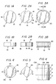
- FIG. 11A and 11B Another way to form abrasive bodies at the corners of an insert is depicted in Figs. 11A and 11B.
- the corner portions 70 of a cemented carbide substrate 72 are truncated and the resulting triangular spaces formed between the rod and container 20 are filled with the abrasive powder 74 (or pre-pressed green compacts) which are then subjected to high temperature and pressure conditions to form an insert 76.
- One way to make multiple inserts simultaneously involves placing substrates in the form of thin disks 80 in respective coplanar chambers 82 of a container 84 (see Fig. 12). A plurality of separate inserts would thus be simultaneously formed in one container during the high temperature/high pressure procedure. This method can be used to form inserts of any desired shape, including round.
- a cemented carbide substrate 90 has a plurality of holes 92 formed therein in a regular pattern, in any suitable manner, e.g., at the time of fabricating the substrate or thereafter.
- the holes extend completely through the substrate and are filled with abrasive material 93 (i.e., powder or compacts) and then the high temperature/high pressure sintering process is applied to the substrate within a container (not shown).
- abrasive material 93 i.e., powder or compacts
- individual inserts 96 are cut from the substrate by wire EDM along the lines 94 extending parallel to the holes 92, whereby the inserts have abrasive bodies 98 at the corners.
- the substrate 90 could be relatively thin, i.e., having a thickness equal to the insert thickness.
- the substrate 90 could be of greater thickness as shown in Fig. 13B, with wire EDM slicing being performed along the lines 100, the lines 100 passing through the holes 92 perpendicular thereto.
- a series of blanks having their corners cut off could be arranged against one another in coplanar fashion such that each hole shown in Fig. 13A would actually be formed by the cut-off corners of four blanks.
- a smaller substrate 102 could be used (see Fig. 14) in which a plurality of holes 104 is formed completely through the substrate. Those holes 104 are spaced inwardly from an outer perimeter of the substrate and are filled with abrasive material prior to a high pressure/high temperature process. Then, the substrate 102 is cut by EDM wire, or machined, along lines 106 to form an insert profile similar to that shown in Fig. 13C.
- the substrate 102 could comprise a thin (wafer) substrate so as to form a single insert, or the substrate could comprise an elongated rod which is transversely sliced to form separate wafers prior to the machining or cutting along lines 106.
- separators 110 are formed of a material which will not bond to, or at least form only a relatively shallow bonding (reaction) zone with, the substrate and superhard abrasive.
- the separators could be formed of Nb, Mo or Zr which could be removed by being dissolved chemically in caustic. The remaining shallow bonding zone could then be ground away.
- the separators could be formed of a material having a high melting temperature and low shear strength, such as NaCl, graphite, mica, talc, Al 2 O 3 , hexagonal boron nitride (HBN) for example. Due to the low shear strength, the separators can be broken off and the bonding zone machined away, as described above.
- the substrates 102 are introduced into a container (not shown) along with the separators 110. To load the container, each separator would be inserted once the grooves of a previously inserted substrate have been filled with abrasive material.
- separators 110 can be used in connection with the methods disclosed earlier herein (except for the method disclosed in connection with Fig. 12).
- the abrasive bodies employed in connection with the present invention can be applied to substrates (blanks) of any suitable shape or which are subsequently ground to a suitable shape (e.g., round, square or non-square rectangular, triangular, rhombic, trapezoidal, etc.), with or without a center hole.
- the abrasive bodies themselves can be of any shape and located anywhere on the insert as long as the cutting work of the finished insert would be performed essentially by the abrasive bodies.
- the abrasive bodies located at the corners are shown as being symmetrical with respect to those corners, the bodies could instead be asymmetrically disposed with respect thereto.
- Abrasive bodies of the same or different shapes may be provided on the same insert.
- the abrasive bodies can, if desired, be reshaped (e.g., by grinding) after being bonded to the substrate.
- the abrasive powder preferably comprises PCD or PCBN particles mixed with other hard and wear-resistant constituents such as carbides, nitrides, carbonitrides, oxides, borides of the metals of groups IVa to VIa of the periodical system preferably Ti as known in the art. Particularly good results have been obtained with compositions of Megadiamond grade MN90.
- the assembly is then subjected to conventional elevated temperatures and pressures for producing high pressure materials, e.g., as disclosed in U.S. Patents 4,991,467 and 5,115,697 (the disclosures of which are incorporated herein by reference).
- the cemented carbide substrate essentially does not take part in the cutting operation performed by the manufactured inserts, its composition is chosen such that it provides a good bond to the PCD or PCBN abrasive, is easy to grind and contains inexpensive components and has suitable fracture resistance.
- a WC-Co cemented carbide having 10-20 % Co by weight, most preferably about 15-17%, is used. Particularly good results have been obtained with a grade of 16% Co.
- titanium based carbonitrides sino-called cermets
- Inserts according to the invention can further be provided with thin wear resistant coatings preferably applied by conventional PVD or CVD methods.
- CVD coatings are normally deposited at about 950-1000 oC and PVD-coatings are preferably a TiN-layer deposited at about 500 °C using a titanium source and nitrogen atmosphere.
- a PVD-layer produced by this technique has compressive residual stresses.
- Example 2 was repeated using coolant and a cutting speed of 500 m/min. The strength of the bond between PCBN and the cemented carbide blank remained sufficient.
- Example 2 was repeated but with a feed rate of 0.5 mm/rev with and without coolant. Two edges of the insert were tested and both were undamaged after 170 passes. They could have been further machined if desired.
- Example 3 was repeated with a 3 mm thick insert and feed rate 0.4 to 0.6 mm/rev wet or dry machining.
- the feed rate was increased from 0.4 to 0.5 mm/rev after 200 passes and then again to 0.6 mm/rev after 400 passes.
- the edge had clean, even flank wear, no crater wear and no signs of chipping or other damage.
- the present invention enables metal cutting inserts to be manufactured having superhard abrasive bodies on both side surfaces of the inserts, in a relatively low-cost manner.
- the inserts thus exhibit very favourable cost per abrasive edge ratio and provide a maximum number of useful cutting edges.
Landscapes
- Engineering & Computer Science (AREA)
- Mechanical Engineering (AREA)
- Chemical & Material Sciences (AREA)
- Ceramic Engineering (AREA)
- Manufacturing & Machinery (AREA)
- Materials Engineering (AREA)
- Structural Engineering (AREA)
- Organic Chemistry (AREA)
- Ceramic Products (AREA)
- Polishing Bodies And Polishing Tools (AREA)
- Drilling Tools (AREA)
- Cutting Tools, Boring Holders, And Turrets (AREA)
Priority Applications (1)
| Application Number | Priority Date | Filing Date | Title |
|---|---|---|---|
| EP03002459A EP1350593B1 (de) | 1995-05-22 | 1996-05-14 | Herstellungsverfahren von Metallschneideinsätzen mit superharten Schleifkörpern |
Applications Claiming Priority (2)
| Application Number | Priority Date | Filing Date | Title |
|---|---|---|---|
| US44649095A | 1995-05-22 | 1995-05-22 | |
| US446490 | 1995-05-22 |
Related Child Applications (1)
| Application Number | Title | Priority Date | Filing Date |
|---|---|---|---|
| EP03002459A Division EP1350593B1 (de) | 1995-05-22 | 1996-05-14 | Herstellungsverfahren von Metallschneideinsätzen mit superharten Schleifkörpern |
Publications (2)
| Publication Number | Publication Date |
|---|---|
| EP0744242A2 true EP0744242A2 (de) | 1996-11-27 |
| EP0744242A3 EP0744242A3 (de) | 1997-08-13 |
Family
ID=23772794
Family Applications (2)
| Application Number | Title | Priority Date | Filing Date |
|---|---|---|---|
| EP96850094A Withdrawn EP0744242A3 (de) | 1995-05-22 | 1996-05-14 | Metallschneideinsätze mit superharten Schleifkörpern und dessen Herstellungsverfahren |
| EP03002459A Expired - Lifetime EP1350593B1 (de) | 1995-05-22 | 1996-05-14 | Herstellungsverfahren von Metallschneideinsätzen mit superharten Schleifkörpern |
Family Applications After (1)
| Application Number | Title | Priority Date | Filing Date |
|---|---|---|---|
| EP03002459A Expired - Lifetime EP1350593B1 (de) | 1995-05-22 | 1996-05-14 | Herstellungsverfahren von Metallschneideinsätzen mit superharten Schleifkörpern |
Country Status (8)
| Country | Link |
|---|---|
| US (2) | US5676496A (de) |
| EP (2) | EP0744242A3 (de) |
| JP (1) | JP3878246B2 (de) |
| KR (1) | KR960040554A (de) |
| CN (1) | CN1075754C (de) |
| AT (1) | ATE550134T1 (de) |
| BR (1) | BR9602395A (de) |
| ZA (1) | ZA963789B (de) |
Cited By (10)
| Publication number | Priority date | Publication date | Assignee | Title |
|---|---|---|---|---|
| WO1998028464A1 (en) * | 1996-12-20 | 1998-07-02 | Sandvik Ab (Publ) | Cubic boron nitride cutting tool |
| WO1998056528A1 (en) * | 1997-06-13 | 1998-12-17 | Sandvik Ab | Method of making endmills |
| WO1999034948A1 (de) * | 1998-01-08 | 1999-07-15 | Hartmetallwerkzeug Fabrik Andreas Maier Gmbh | Messerkopf mit ein- bis dreidimensional verstellbarem schneideinsatz und mit formschlüssig aufgenommenem schneideinsatz |
| WO2000015372A1 (en) * | 1998-06-15 | 2000-03-23 | Seco Tools Ab; (Publ) | A method of turning a rotating metallic work piece |
| WO2000020149A1 (en) * | 1998-10-08 | 2000-04-13 | De Beers Industrial Diamonds (Proprietary) Limited | Tool component |
| EP1043291A1 (de) * | 1999-04-07 | 2000-10-11 | Sandvik Aktiebolag | Für die Herstellung von Schneidwerkzeugen geeignetes Pulver aus kubischem Bornitrid und Verfahren zu seiner Herstellung |
| WO2001041974A3 (en) * | 1999-12-03 | 2002-01-03 | Ultimate Abrasive Systems Llc | Process for making an abrasive sintered product |
| WO2002022311A1 (en) * | 2000-09-13 | 2002-03-21 | Element Six (Pty) Ltd | Method of making a tool insert |
| CN104097154A (zh) * | 2014-07-05 | 2014-10-15 | 郑州磨料磨具磨削研究所有限公司 | 超硬材料磨盘磨料块制造方法及超硬材料磨盘制造方法 |
| CN118645319A (zh) * | 2024-06-25 | 2024-09-13 | 湖南长缆智能科技有限公司 | 电缆处理系统及方法 |
Families Citing this family (66)
| Publication number | Priority date | Publication date | Assignee | Title |
|---|---|---|---|---|
| US5984005A (en) * | 1995-09-22 | 1999-11-16 | Weatherford/Lamb, Inc. | Wellbore milling inserts and mills |
| US6170576B1 (en) | 1995-09-22 | 2001-01-09 | Weatherford/Lamb, Inc. | Mills for wellbore operations |
| US6120570A (en) * | 1996-02-14 | 2000-09-19 | Smith International | Process for manufacturing inserts with holes for clamping |
| SE511587C2 (sv) | 1997-07-08 | 1999-10-25 | Sandvik Ab | Sätt att tillverka skär med hål för fastspänning |
| US6361873B1 (en) * | 1997-07-31 | 2002-03-26 | Smith International, Inc. | Composite constructions having ordered microstructures |
| US6224473B1 (en) | 1997-08-07 | 2001-05-01 | Norton Company | Abrasive inserts for grinding bimetallic components |
| US6106957A (en) | 1998-03-19 | 2000-08-22 | Smith International, Inc. | Metal-matrix diamond or cubic boron nitride composites |
| JP3573256B2 (ja) * | 1998-07-27 | 2004-10-06 | 住友電気工業株式会社 | Al2O3被覆cBN基焼結体切削工具 |
| AU6169299A (en) * | 1998-10-02 | 2000-04-26 | Sandvik Ab | Pcbn tips and coatings for use in cutting and machining hard materials |
| US6161990A (en) * | 1998-11-12 | 2000-12-19 | Kennametal Inc. | Cutting insert with improved flank surface roughness and method of making the same |
| US6138358A (en) * | 1999-02-18 | 2000-10-31 | Dana Corporation | Method of manufacturing a vehicle body and frame assembly |
| US6498242B1 (en) * | 1999-02-19 | 2002-12-24 | E. I. Du Pont De Nemours And Company | Biological method for the production of adipic acid and intermediates |
| SE519862C2 (sv) * | 1999-04-07 | 2003-04-15 | Sandvik Ab | Sätt att tillverka ett skär bestående av en PcBN-kropp och en hårdmetall- eller cermet-kropp |
| US6599062B1 (en) * | 1999-06-11 | 2003-07-29 | Kennametal Pc Inc. | Coated PCBN cutting inserts |
| SE0000143L (sv) * | 2000-01-19 | 2001-07-20 | Sandvik Ab | Metallbearbetningsskär med superhårda abrasiva kroppar |
| GB2362388B (en) * | 2000-05-15 | 2004-09-29 | Smith International | Woven and packed composite constructions |
| US6988858B2 (en) * | 2001-02-28 | 2006-01-24 | Kennametal Inc. | Oxidation-resistant cutting assembly |
| US6681488B2 (en) | 2001-04-06 | 2004-01-27 | Dana Corporation | Method of manufacturing a vehicle body and frame assembly |
| DE10159431B4 (de) * | 2001-12-04 | 2005-10-20 | Mapal Fab Praezision | Werkzeug zur Feinstbearbeitung von Oberflächen |
| CA2476780A1 (en) * | 2002-02-21 | 2003-08-28 | Element Six (Pty) Ltd. | Tool insert |
| KR20030085870A (ko) * | 2002-05-02 | 2003-11-07 | 한경렬 | 절삭공구용 인서트의 제조방법 |
| US6837915B2 (en) * | 2002-09-20 | 2005-01-04 | Scm Metal Products, Inc. | High density, metal-based materials having low coefficients of friction and wear rates |
| US20060249308A1 (en) * | 2003-02-11 | 2006-11-09 | Klaus Tank | Cutting element |
| US20060032677A1 (en) * | 2003-02-12 | 2006-02-16 | Smith International, Inc. | Novel bits and cutting structures |
| US7322776B2 (en) * | 2003-05-14 | 2008-01-29 | Diamond Innovations, Inc. | Cutting tool inserts and methods to manufacture |
| JP4782672B2 (ja) * | 2003-06-03 | 2011-09-28 | サンドビック インテレクチュアル プロパティー アクティエボラーグ | 割り出し可能な切削インサート及びこの切削インサートの製造方法 |
| US20050230150A1 (en) * | 2003-08-28 | 2005-10-20 | Smith International, Inc. | Coated diamonds for use in impregnated diamond bits |
| US20050210755A1 (en) * | 2003-09-05 | 2005-09-29 | Cho Hyun S | Doubled-sided and multi-layered PCBN and PCD abrasive articles |
| US7243744B2 (en) | 2003-12-02 | 2007-07-17 | Smith International, Inc. | Randomly-oriented composite constructions |
| KR20060129249A (ko) * | 2004-01-06 | 2006-12-15 | 엘리먼트 씩스 리미티드 | 공구 인서트의 제조 방법 |
| US20050183893A1 (en) * | 2004-01-13 | 2005-08-25 | Sandvik Ab | Indexable cutting inserts and methods for producing the same |
| US8178220B2 (en) * | 2004-04-30 | 2012-05-15 | Sumitomo Electric Hardmetal Corp. | Surface-covered cubic boron nitride sintered body tool and method of manufacturing the same |
| US20050271483A1 (en) * | 2004-06-02 | 2005-12-08 | Sandvik Ab | Indexable cutting inserts and methods for producing the same |
| US7350599B2 (en) * | 2004-10-18 | 2008-04-01 | Smith International, Inc. | Impregnated diamond cutting structures |
| US7441610B2 (en) * | 2005-02-25 | 2008-10-28 | Smith International, Inc. | Ultrahard composite constructions |
| WO2007017745A1 (en) * | 2005-08-11 | 2007-02-15 | Element Six (Production) (Pty) Ltd | Polycrystalline diamond abrasive element and method of its production |
| CA2523881A1 (en) * | 2005-10-11 | 2007-04-11 | Postle Industries Inc. | Hardsurfacing consumable |
| AU2006325088A1 (en) * | 2005-12-12 | 2007-06-21 | Element Six (Production) (Pty) Ltd | PCBN cutting tool components |
| US7866419B2 (en) * | 2006-07-19 | 2011-01-11 | Smith International, Inc. | Diamond impregnated bits using a novel cutting structure |
| US7682557B2 (en) * | 2006-12-15 | 2010-03-23 | Smith International, Inc. | Multiple processes of high pressures and temperatures for sintered bodies |
| US8052765B2 (en) * | 2007-04-03 | 2011-11-08 | Cho H Sam | Contoured PCD and PCBN for twist drill tips and end mills and methods of forming the same |
| US9468980B2 (en) | 2007-04-03 | 2016-10-18 | H. Sam Cho | Contoured PCD and PCBN segments for cutting tools containing such segments |
| US8517125B2 (en) * | 2007-05-18 | 2013-08-27 | Smith International, Inc. | Impregnated material with variable erosion properties for rock drilling |
| US20090120008A1 (en) * | 2007-11-09 | 2009-05-14 | Smith International, Inc. | Impregnated drill bits and methods for making the same |
| US20100104874A1 (en) * | 2008-10-29 | 2010-04-29 | Smith International, Inc. | High pressure sintering with carbon additives |
| US20100150678A1 (en) * | 2008-12-17 | 2010-06-17 | Gm Global Technology Operations, Inc. | Method of broaching hardened steel workpieces with diamond-tipped tools |
| IL196439A (en) | 2009-01-11 | 2013-04-30 | Iscar Ltd | Method of grooving superalloys and cutting insert therefor |
| US9004199B2 (en) * | 2009-06-22 | 2015-04-14 | Smith International, Inc. | Drill bits and methods of manufacturing such drill bits |
| CN101644549B (zh) * | 2009-07-28 | 2011-06-15 | 华南理工大学 | 一种微沟槽与纤维的复合多孔结构及其制造方法 |
| JP5793507B2 (ja) * | 2010-01-07 | 2015-10-14 | ジーケーエヌ シンター メタルズ、エル・エル・シー | 工作機械及び該工作機械の製造方法 |
| US20110259150A1 (en) * | 2010-04-23 | 2011-10-27 | Hall David R | Disc Cutter for an Earth Boring System |
| EP2593255B1 (de) * | 2010-07-13 | 2016-10-12 | Element Six Limited | Herstellungsverfahren für eine konstruktion einer wendeschneidplatte |
| EP2614906B1 (de) * | 2010-09-07 | 2020-07-15 | Sumitomo Electric Hardmetal Corp. | Schneidewerkzeug |
| CN103209794B (zh) | 2010-09-08 | 2015-11-25 | 六号元素有限公司 | 自烧结的多晶立方氮化硼(pcbn)切割元件和形成自烧结pcbn切割元件的方法 |
| GB201020967D0 (en) * | 2010-12-10 | 2011-01-26 | Element Six Production Pty Ltd | Bit for a rotary drill |
| US8507082B2 (en) | 2011-03-25 | 2013-08-13 | Kennametal Inc. | CVD coated polycrystalline c-BN cutting tools |
| CN102145403B (zh) * | 2011-04-07 | 2013-01-09 | 宁波江丰电子材料有限公司 | 钨合金靶材铣削加工方法 |
| CN102501027A (zh) * | 2011-11-18 | 2012-06-20 | 宁波江丰电子材料有限公司 | 钴靶材的加工方法 |
| CN103362445A (zh) * | 2012-04-10 | 2013-10-23 | 吴庆华 | 一种金刚石夹心式硬质合金矿山凿岩刀片制备技术 |
| US9028953B2 (en) | 2013-01-11 | 2015-05-12 | Kennametal Inc. | CVD coated polycrystalline c-BN cutting tools |
| US9428967B2 (en) | 2013-03-01 | 2016-08-30 | Baker Hughes Incorporated | Polycrystalline compact tables for cutting elements and methods of fabrication |
| US11045813B2 (en) | 2013-10-28 | 2021-06-29 | Postle Industries, Inc. | Hammermill system, hammer and method |
| US20170014922A1 (en) * | 2015-07-15 | 2017-01-19 | Caterpillar Inc. | Power Skiving Assembly and Method of Operation of Same |
| EP3421160B1 (de) * | 2017-06-30 | 2022-08-10 | Seco Tools Ab | Schneideinsatz und verfahren zur herstellung eines schneideinsatzes |
| CN109262481A (zh) * | 2018-01-22 | 2019-01-25 | 深圳西斯特科技有限公司 | 一种新型滚轮的磨料排布方式 |
| TWI650064B (zh) * | 2018-02-14 | 2019-02-11 | 慶璉實業股份有限公司 | 樹剪刀座製造方法 |
Family Cites Families (27)
| Publication number | Priority date | Publication date | Assignee | Title |
|---|---|---|---|---|
| US2002229A (en) * | 1932-04-11 | 1935-05-21 | Jessop Steel Company Washingto | Process of manufacturing composite metal articles |
| SE305791B (de) * | 1964-02-06 | 1968-11-04 | Diadur Ab | |
| GB2037629B (en) * | 1978-12-06 | 1982-10-13 | Henderson Diamond Tool Co Ltd | Locating tips or inserts onto tools |
| IL60042A (en) * | 1979-05-16 | 1983-05-15 | De Beers Ind Diamond | Abrasive bodies |
| JPS603922B2 (ja) * | 1980-09-03 | 1985-01-31 | 日本油脂株式会社 | 切削工具 |
| US4561810A (en) * | 1981-12-16 | 1985-12-31 | General Electric Company | Bi-level cutting insert |
| IE59168B1 (en) * | 1985-11-04 | 1994-01-12 | De Beers Ind Diamond | Method of making a drill blank |
| US4690691A (en) * | 1986-02-18 | 1987-09-01 | General Electric Company | Polycrystalline diamond and CBN cutting tools |
| US4662896A (en) * | 1986-02-19 | 1987-05-05 | Strata Bit Corporation | Method of making an abrasive cutting element |
| US4714385A (en) * | 1986-02-27 | 1987-12-22 | General Electric Company | Polycrystalline diamond and CBN cutting tools |
| IE62468B1 (en) * | 1987-02-09 | 1995-02-08 | De Beers Ind Diamond | Abrasive product |
| SU1537384A1 (ru) * | 1987-10-28 | 1990-01-23 | Мариупольский металлургический институт | Режуща пластина |
| DE8800342U1 (de) * | 1988-01-14 | 1988-02-25 | Diamant-Gesellschaft Tesch GmbH, 7140 Ludwigsburg | Werkzeug für Dreh- oder Fräsmaschinen |
| GB8916955D0 (en) * | 1989-07-25 | 1989-09-13 | Pacini Ltd | Tool insert |
| US4991467A (en) | 1989-08-14 | 1991-02-12 | Smith International, Inc. | Diamond twist drill blank |
| US5183362A (en) * | 1990-01-10 | 1993-02-02 | Nippon Oil And Fats Co., Ltd. | Cutting tool assembly |
| CA2036930C (en) * | 1990-02-27 | 1996-01-09 | Hitoshi Fukuoka | Cutting insert |
| DE69112465T2 (de) * | 1990-03-30 | 1996-03-28 | Sumitomo Electric Industries | Polykristallines Diamantwerkzeug und Verfahren für seine Herstellung. |
| CN1024766C (zh) * | 1990-04-18 | 1994-06-01 | Gn工具株式会社 | 可更换型刀片及其制造方法 |
| SE9004123D0 (sv) * | 1990-12-21 | 1990-12-21 | Sandvik Ab | Diamantimpregnerat haardmaterial |
| JPH04336903A (ja) * | 1991-05-10 | 1992-11-25 | Hitachi Tool Eng Ltd | 複合焼結チップ及びその製造方法 |
| US5115697A (en) | 1991-08-16 | 1992-05-26 | Smith International, Inc. | Diamond rotary cutter flute geometry |
| JPH05162007A (ja) * | 1991-12-13 | 1993-06-29 | Mitsubishi Materials Corp | 人工ダイヤモンド被覆炭化タングステン基超硬合金製スローアウェイ切削チップ |
| SE9301811D0 (sv) * | 1993-05-27 | 1993-05-27 | Sandvik Ab | Cutting insert |
| JPH0726368A (ja) * | 1993-07-10 | 1995-01-27 | Hitachi Tool Eng Ltd | 耐摩耗性に優れた被覆切削工具 |
| DE4341503A1 (de) * | 1993-12-06 | 1995-06-08 | Beck August Gmbh Co | Vorrichtung zum Feinbearbeiten von Bohrungen |
| JPH08206902A (ja) * | 1994-12-01 | 1996-08-13 | Sumitomo Electric Ind Ltd | 切削用焼結体チップおよびその製造方法 |
-
1996
- 1996-05-13 ZA ZA963789A patent/ZA963789B/xx unknown
- 1996-05-14 AT AT03002459T patent/ATE550134T1/de active
- 1996-05-14 EP EP96850094A patent/EP0744242A3/de not_active Withdrawn
- 1996-05-14 EP EP03002459A patent/EP1350593B1/de not_active Expired - Lifetime
- 1996-05-20 CN CN96105095A patent/CN1075754C/zh not_active Expired - Fee Related
- 1996-05-21 BR BR9602395-3A patent/BR9602395A/pt not_active IP Right Cessation
- 1996-05-21 KR KR19960017152A patent/KR960040554A/ko not_active Ceased
- 1996-05-22 JP JP12741496A patent/JP3878246B2/ja not_active Expired - Fee Related
- 1996-09-30 US US08/723,810 patent/US5676496A/en not_active Expired - Lifetime
-
1997
- 1997-07-03 US US08/888,055 patent/US5813105A/en not_active Expired - Lifetime
Cited By (14)
| Publication number | Priority date | Publication date | Assignee | Title |
|---|---|---|---|---|
| US6090476A (en) * | 1996-12-20 | 2000-07-18 | Sandvik Ab | Cubic boron nitride cutting tool |
| WO1998028464A1 (en) * | 1996-12-20 | 1998-07-02 | Sandvik Ab (Publ) | Cubic boron nitride cutting tool |
| WO1998056528A1 (en) * | 1997-06-13 | 1998-12-17 | Sandvik Ab | Method of making endmills |
| WO1999034948A1 (de) * | 1998-01-08 | 1999-07-15 | Hartmetallwerkzeug Fabrik Andreas Maier Gmbh | Messerkopf mit ein- bis dreidimensional verstellbarem schneideinsatz und mit formschlüssig aufgenommenem schneideinsatz |
| US7037050B1 (en) | 1998-01-08 | 2006-05-02 | Hartmetallwerkzeugfabrik Andreas Maier Gmbh | Milling head with one to three-dimensional adjustable cutting insert and with a positive fitting cutting insert |
| CN1103258C (zh) * | 1998-06-15 | 2003-03-19 | 塞科机床公司 | 车削旋转金属工件的方法 |
| WO2000015372A1 (en) * | 1998-06-15 | 2000-03-23 | Seco Tools Ab; (Publ) | A method of turning a rotating metallic work piece |
| WO2000020149A1 (en) * | 1998-10-08 | 2000-04-13 | De Beers Industrial Diamonds (Proprietary) Limited | Tool component |
| US6579045B1 (en) | 1998-10-08 | 2003-06-17 | Robert Fries | Tool component |
| EP1043291A1 (de) * | 1999-04-07 | 2000-10-11 | Sandvik Aktiebolag | Für die Herstellung von Schneidwerkzeugen geeignetes Pulver aus kubischem Bornitrid und Verfahren zu seiner Herstellung |
| WO2001041974A3 (en) * | 1999-12-03 | 2002-01-03 | Ultimate Abrasive Systems Llc | Process for making an abrasive sintered product |
| WO2002022311A1 (en) * | 2000-09-13 | 2002-03-21 | Element Six (Pty) Ltd | Method of making a tool insert |
| CN104097154A (zh) * | 2014-07-05 | 2014-10-15 | 郑州磨料磨具磨削研究所有限公司 | 超硬材料磨盘磨料块制造方法及超硬材料磨盘制造方法 |
| CN118645319A (zh) * | 2024-06-25 | 2024-09-13 | 湖南长缆智能科技有限公司 | 电缆处理系统及方法 |
Also Published As
| Publication number | Publication date |
|---|---|
| US5813105A (en) | 1998-09-29 |
| KR960040554A (de) | 1996-12-17 |
| ZA963789B (en) | 1997-01-27 |
| EP1350593B1 (de) | 2012-03-21 |
| JP3878246B2 (ja) | 2007-02-07 |
| BR9602395A (pt) | 1999-10-13 |
| CN1075754C (zh) | 2001-12-05 |
| JPH09117808A (ja) | 1997-05-06 |
| EP1350593A2 (de) | 2003-10-08 |
| EP1350593A3 (de) | 2003-12-03 |
| CN1141223A (zh) | 1997-01-29 |
| EP0744242A3 (de) | 1997-08-13 |
| US5676496A (en) | 1997-10-14 |
| ATE550134T1 (de) | 2012-04-15 |
Similar Documents
| Publication | Publication Date | Title |
|---|---|---|
| EP1350593B1 (de) | Herstellungsverfahren von Metallschneideinsätzen mit superharten Schleifkörpern | |
| EP0827442B1 (de) | Herstellungsverfahren von metallschneideeinsätze mit superharten schleifkörpern | |
| US8105000B2 (en) | Tool insert | |
| US7074247B2 (en) | Method of making a composite abrasive compact | |
| AU602256B2 (en) | Abrasive products | |
| US6447560B2 (en) | Method for forming a superabrasive polycrystalline cutting tool with an integral chipbreaker feature | |
| EP2864070B1 (de) | Verfahren zur herstellung von schneideinsätzen | |
| AU2002212567A1 (en) | A method of making a composite abrasive compact | |
| EP0941791B1 (de) | Schleifkörper | |
| KR100555823B1 (ko) | 드릴블랭크제조방법 | |
| HK1018031A (en) | Metal cutting inserts having superhard abrasive bodies and methods of making same | |
| ZA200302444B (en) | A method of making a composite abrasive compact. | |
| ZA200406386B (en) | Tool insert. |
Legal Events
| Date | Code | Title | Description |
|---|---|---|---|
| PUAI | Public reference made under article 153(3) epc to a published international application that has entered the european phase |
Free format text: ORIGINAL CODE: 0009012 |
|
| AK | Designated contracting states |
Kind code of ref document: A2 Designated state(s): AT BE CH DE DK ES FI FR GB GR IE IT LI LU MC NL PT SE |
|
| PUAL | Search report despatched |
Free format text: ORIGINAL CODE: 0009013 |
|
| 17P | Request for examination filed |
Effective date: 19970513 |
|
| AK | Designated contracting states |
Kind code of ref document: A3 Designated state(s): AT BE CH DE DK ES FI FR GB GR IE IT LI LU MC NL PT SE |
|
| 17Q | First examination report despatched |
Effective date: 19990507 |
|
| STAA | Information on the status of an ep patent application or granted ep patent |
Free format text: STATUS: THE APPLICATION IS DEEMED TO BE WITHDRAWN |
|
| 18D | Application deemed to be withdrawn |
Effective date: 20030213 |