EP0744274A2 - Hydropneumatischer fasergewickelter Druckbehälter - Google Patents
Hydropneumatischer fasergewickelter Druckbehälter Download PDFInfo
- Publication number
- EP0744274A2 EP0744274A2 EP96300917A EP96300917A EP0744274A2 EP 0744274 A2 EP0744274 A2 EP 0744274A2 EP 96300917 A EP96300917 A EP 96300917A EP 96300917 A EP96300917 A EP 96300917A EP 0744274 A2 EP0744274 A2 EP 0744274A2
- Authority
- EP
- European Patent Office
- Prior art keywords
- revolution
- pressure vessel
- inflection point
- diaphragm
- tank
- Prior art date
- Legal status (The legal status is an assumption and is not a legal conclusion. Google has not performed a legal analysis and makes no representation as to the accuracy of the status listed.)
- Granted
Links
Images





Classifications
-
- F—MECHANICAL ENGINEERING; LIGHTING; HEATING; WEAPONS; BLASTING
- F17—STORING OR DISTRIBUTING GASES OR LIQUIDS
- F17C—VESSELS FOR CONTAINING OR STORING COMPRESSED, LIQUEFIED OR SOLIDIFIED GASES; FIXED-CAPACITY GAS-HOLDERS; FILLING VESSELS WITH, OR DISCHARGING FROM VESSELS, COMPRESSED, LIQUEFIED, OR SOLIDIFIED GASES
- F17C1/00—Pressure vessels, e.g. gas cylinder, gas tank, replaceable cartridge
- F17C1/16—Pressure vessels, e.g. gas cylinder, gas tank, replaceable cartridge constructed of plastics materials
-
- B—PERFORMING OPERATIONS; TRANSPORTING
- B29—WORKING OF PLASTICS; WORKING OF SUBSTANCES IN A PLASTIC STATE IN GENERAL
- B29C—SHAPING OR JOINING OF PLASTICS; SHAPING OF MATERIAL IN A PLASTIC STATE, NOT OTHERWISE PROVIDED FOR; AFTER-TREATMENT OF THE SHAPED PRODUCTS, e.g. REPAIRING
- B29C53/00—Shaping by bending, folding, twisting, straightening or flattening; Apparatus therefor
- B29C53/56—Winding and joining, e.g. winding spirally
-
- F—MECHANICAL ENGINEERING; LIGHTING; HEATING; WEAPONS; BLASTING
- F17—STORING OR DISTRIBUTING GASES OR LIQUIDS
- F17C—VESSELS FOR CONTAINING OR STORING COMPRESSED, LIQUEFIED OR SOLIDIFIED GASES; FIXED-CAPACITY GAS-HOLDERS; FILLING VESSELS WITH, OR DISCHARGING FROM VESSELS, COMPRESSED, LIQUEFIED, OR SOLIDIFIED GASES
- F17C2201/00—Vessel construction, in particular geometry, arrangement or size
- F17C2201/01—Shape
- F17C2201/0104—Shape cylindrical
- F17C2201/0109—Shape cylindrical with exteriorly curved end-piece
-
- F—MECHANICAL ENGINEERING; LIGHTING; HEATING; WEAPONS; BLASTING
- F17—STORING OR DISTRIBUTING GASES OR LIQUIDS
- F17C—VESSELS FOR CONTAINING OR STORING COMPRESSED, LIQUEFIED OR SOLIDIFIED GASES; FIXED-CAPACITY GAS-HOLDERS; FILLING VESSELS WITH, OR DISCHARGING FROM VESSELS, COMPRESSED, LIQUEFIED, OR SOLIDIFIED GASES
- F17C2201/00—Vessel construction, in particular geometry, arrangement or size
- F17C2201/01—Shape
- F17C2201/0147—Shape complex
- F17C2201/0166—Shape complex divided in several chambers
-
- F—MECHANICAL ENGINEERING; LIGHTING; HEATING; WEAPONS; BLASTING
- F17—STORING OR DISTRIBUTING GASES OR LIQUIDS
- F17C—VESSELS FOR CONTAINING OR STORING COMPRESSED, LIQUEFIED OR SOLIDIFIED GASES; FIXED-CAPACITY GAS-HOLDERS; FILLING VESSELS WITH, OR DISCHARGING FROM VESSELS, COMPRESSED, LIQUEFIED, OR SOLIDIFIED GASES
- F17C2201/00—Vessel construction, in particular geometry, arrangement or size
- F17C2201/01—Shape
- F17C2201/0176—Shape variable
- F17C2201/018—Shape variable with bladders
-
- F—MECHANICAL ENGINEERING; LIGHTING; HEATING; WEAPONS; BLASTING
- F17—STORING OR DISTRIBUTING GASES OR LIQUIDS
- F17C—VESSELS FOR CONTAINING OR STORING COMPRESSED, LIQUEFIED OR SOLIDIFIED GASES; FIXED-CAPACITY GAS-HOLDERS; FILLING VESSELS WITH, OR DISCHARGING FROM VESSELS, COMPRESSED, LIQUEFIED, OR SOLIDIFIED GASES
- F17C2201/00—Vessel construction, in particular geometry, arrangement or size
- F17C2201/01—Shape
- F17C2201/0176—Shape variable
- F17C2201/0185—Shape variable with separating membrane
-
- F—MECHANICAL ENGINEERING; LIGHTING; HEATING; WEAPONS; BLASTING
- F17—STORING OR DISTRIBUTING GASES OR LIQUIDS
- F17C—VESSELS FOR CONTAINING OR STORING COMPRESSED, LIQUEFIED OR SOLIDIFIED GASES; FIXED-CAPACITY GAS-HOLDERS; FILLING VESSELS WITH, OR DISCHARGING FROM VESSELS, COMPRESSED, LIQUEFIED, OR SOLIDIFIED GASES
- F17C2203/00—Vessel construction, in particular walls or details thereof
- F17C2203/06—Materials for walls or layers thereof; Properties or structures of walls or their materials
- F17C2203/0602—Wall structures; Special features thereof
- F17C2203/0604—Liners
-
- F—MECHANICAL ENGINEERING; LIGHTING; HEATING; WEAPONS; BLASTING
- F17—STORING OR DISTRIBUTING GASES OR LIQUIDS
- F17C—VESSELS FOR CONTAINING OR STORING COMPRESSED, LIQUEFIED OR SOLIDIFIED GASES; FIXED-CAPACITY GAS-HOLDERS; FILLING VESSELS WITH, OR DISCHARGING FROM VESSELS, COMPRESSED, LIQUEFIED, OR SOLIDIFIED GASES
- F17C2203/00—Vessel construction, in particular walls or details thereof
- F17C2203/06—Materials for walls or layers thereof; Properties or structures of walls or their materials
- F17C2203/0634—Materials for walls or layers thereof
- F17C2203/0658—Synthetics
- F17C2203/0663—Synthetics in form of fibers or filaments
-
- F—MECHANICAL ENGINEERING; LIGHTING; HEATING; WEAPONS; BLASTING
- F17—STORING OR DISTRIBUTING GASES OR LIQUIDS
- F17C—VESSELS FOR CONTAINING OR STORING COMPRESSED, LIQUEFIED OR SOLIDIFIED GASES; FIXED-CAPACITY GAS-HOLDERS; FILLING VESSELS WITH, OR DISCHARGING FROM VESSELS, COMPRESSED, LIQUEFIED, OR SOLIDIFIED GASES
- F17C2203/00—Vessel construction, in particular walls or details thereof
- F17C2203/06—Materials for walls or layers thereof; Properties or structures of walls or their materials
- F17C2203/0634—Materials for walls or layers thereof
- F17C2203/0658—Synthetics
- F17C2203/0663—Synthetics in form of fibers or filaments
- F17C2203/067—Synthetics in form of fibers or filaments helically wound
-
- F—MECHANICAL ENGINEERING; LIGHTING; HEATING; WEAPONS; BLASTING
- F17—STORING OR DISTRIBUTING GASES OR LIQUIDS
- F17C—VESSELS FOR CONTAINING OR STORING COMPRESSED, LIQUEFIED OR SOLIDIFIED GASES; FIXED-CAPACITY GAS-HOLDERS; FILLING VESSELS WITH, OR DISCHARGING FROM VESSELS, COMPRESSED, LIQUEFIED, OR SOLIDIFIED GASES
- F17C2205/00—Vessel construction, in particular mounting arrangements, attachments or identifications means
- F17C2205/03—Fluid connections, filters, valves, closure means or other attachments
- F17C2205/0302—Fittings, valves, filters, or components in connection with the gas storage device
- F17C2205/0323—Valves
-
- F—MECHANICAL ENGINEERING; LIGHTING; HEATING; WEAPONS; BLASTING
- F17—STORING OR DISTRIBUTING GASES OR LIQUIDS
- F17C—VESSELS FOR CONTAINING OR STORING COMPRESSED, LIQUEFIED OR SOLIDIFIED GASES; FIXED-CAPACITY GAS-HOLDERS; FILLING VESSELS WITH, OR DISCHARGING FROM VESSELS, COMPRESSED, LIQUEFIED, OR SOLIDIFIED GASES
- F17C2205/00—Vessel construction, in particular mounting arrangements, attachments or identifications means
- F17C2205/03—Fluid connections, filters, valves, closure means or other attachments
- F17C2205/0302—Fittings, valves, filters, or components in connection with the gas storage device
- F17C2205/0323—Valves
- F17C2205/0335—Check-valves or non-return valves
-
- F—MECHANICAL ENGINEERING; LIGHTING; HEATING; WEAPONS; BLASTING
- F17—STORING OR DISTRIBUTING GASES OR LIQUIDS
- F17C—VESSELS FOR CONTAINING OR STORING COMPRESSED, LIQUEFIED OR SOLIDIFIED GASES; FIXED-CAPACITY GAS-HOLDERS; FILLING VESSELS WITH, OR DISCHARGING FROM VESSELS, COMPRESSED, LIQUEFIED, OR SOLIDIFIED GASES
- F17C2205/00—Vessel construction, in particular mounting arrangements, attachments or identifications means
- F17C2205/03—Fluid connections, filters, valves, closure means or other attachments
- F17C2205/0388—Arrangement of valves, regulators, filters
- F17C2205/0394—Arrangement of valves, regulators, filters in direct contact with the pressure vessel
- F17C2205/0397—Arrangement of valves, regulators, filters in direct contact with the pressure vessel on both sides of the pressure vessel
-
- F—MECHANICAL ENGINEERING; LIGHTING; HEATING; WEAPONS; BLASTING
- F17—STORING OR DISTRIBUTING GASES OR LIQUIDS
- F17C—VESSELS FOR CONTAINING OR STORING COMPRESSED, LIQUEFIED OR SOLIDIFIED GASES; FIXED-CAPACITY GAS-HOLDERS; FILLING VESSELS WITH, OR DISCHARGING FROM VESSELS, COMPRESSED, LIQUEFIED, OR SOLIDIFIED GASES
- F17C2209/00—Vessel construction, in particular methods of manufacturing
- F17C2209/21—Shaping processes
- F17C2209/2154—Winding
- F17C2209/2163—Winding with a mandrel
-
- F—MECHANICAL ENGINEERING; LIGHTING; HEATING; WEAPONS; BLASTING
- F17—STORING OR DISTRIBUTING GASES OR LIQUIDS
- F17C—VESSELS FOR CONTAINING OR STORING COMPRESSED, LIQUEFIED OR SOLIDIFIED GASES; FIXED-CAPACITY GAS-HOLDERS; FILLING VESSELS WITH, OR DISCHARGING FROM VESSELS, COMPRESSED, LIQUEFIED, OR SOLIDIFIED GASES
- F17C2209/00—Vessel construction, in particular methods of manufacturing
- F17C2209/23—Manufacturing of particular parts or at special locations
- F17C2209/232—Manufacturing of particular parts or at special locations of walls
-
- F—MECHANICAL ENGINEERING; LIGHTING; HEATING; WEAPONS; BLASTING
- F17—STORING OR DISTRIBUTING GASES OR LIQUIDS
- F17C—VESSELS FOR CONTAINING OR STORING COMPRESSED, LIQUEFIED OR SOLIDIFIED GASES; FIXED-CAPACITY GAS-HOLDERS; FILLING VESSELS WITH, OR DISCHARGING FROM VESSELS, COMPRESSED, LIQUEFIED, OR SOLIDIFIED GASES
- F17C2223/00—Handled fluid before transfer, i.e. state of fluid when stored in the vessel or before transfer from the vessel
- F17C2223/01—Handled fluid before transfer, i.e. state of fluid when stored in the vessel or before transfer from the vessel characterised by the phase
- F17C2223/0107—Single phase
- F17C2223/0123—Single phase gaseous, e.g. CNG, GNC
-
- F—MECHANICAL ENGINEERING; LIGHTING; HEATING; WEAPONS; BLASTING
- F17—STORING OR DISTRIBUTING GASES OR LIQUIDS
- F17C—VESSELS FOR CONTAINING OR STORING COMPRESSED, LIQUEFIED OR SOLIDIFIED GASES; FIXED-CAPACITY GAS-HOLDERS; FILLING VESSELS WITH, OR DISCHARGING FROM VESSELS, COMPRESSED, LIQUEFIED, OR SOLIDIFIED GASES
- F17C2223/00—Handled fluid before transfer, i.e. state of fluid when stored in the vessel or before transfer from the vessel
- F17C2223/01—Handled fluid before transfer, i.e. state of fluid when stored in the vessel or before transfer from the vessel characterised by the phase
- F17C2223/0107—Single phase
- F17C2223/013—Single phase liquid
Definitions
- This invention relates to filament-wound pressure vessels and, more particularly, to a filament-wound hydropneumatic accumulator tank containing a flexible diaphragm which separates the interior of the tank into a compressible gas-containing chamber and a liquid-containing chamber.
- a stored energy device that can provide instantaneous water pressure to some type of demand.
- the pressure vessel has become an accepted method of providing this water pressure.
- the tank is generally connected in line with a supply source that has a pumping device.
- This pumping device is not capable of providing instantaneous pressure, nor is it recommended that the pumping device operate in a manner that is cycling in unison with the demand for the water. This can reduce the life of the pumping device.
- a pressure tank acts as a storage device that can supply water under pressure for low demand periods without requiring the pumping device to turn on. For higher demand periods, the tank will allow the pump to run for recommended minimum periods while not interrupting the demand requirements. In order for the tank to act in this manner, air under pressure contained in the tank is compressed as the water is pumped into the tank. As more water enters the tank, a pressure rise results, and the pump will shut off at a predetermined sensed pressure. The cycle will not repeat until a demand relieves the tank pressure to a predetermined low sensed pressure which will turn on the pump to refill the tank.
- Most accumulator tanks provide a flexible barrier between the air and water to prevent the loss of air and, therefore, air pressure in the system.
- the technique in which air and water is separated may be by employing a diaphragm or flexible membrane which is attached to the inner wall of the tank to separate the air from the water.
- a second technique is to employ an air cell wherein a sealed bladder containing air is positioned in the tank with access to the interior of the bladder by an exterior air valve.
- a similar arrangement may be used by containing water within the cell which is surrounded by pressurized air.
- a diaphragm-type separator may be constructed from a relatively heavy gauge plastic, or desirably, butyl rubber, and may be shaped to conform to the cross-section of the tank to eliminate stretching.
- This invention provides a fiber-reinforced hydropneumatic pressure vessel which provides a simplified seal and diaphragm combination between the mating halves of cup-shaped tank liners.
- the cup-shaped tank liners preferably have an isotensoid-shaped surface which provides uniform tensile loading on the filaments which provide the structural integrity of the vessel.
- the hydropneumatic filament-wound pressure vessel comprises first and second cup-shaped plastic tank liners having circular overlapping, interlocking open end portions which enable the liners to fit together and be centered.
- the liners overlap to form a receptacle into which an O-ring is inserted.
- the end portions have first and second end faces which mate in face-to-face apposition so that the cup-shaped plastic tank liners define a continuous outer surface.
- This surface is an isotensoid surface formed by face-to-face geodesic domes which define an interior pressure chamber.
- One of the tank liners or domes has an inner axially-extending cylindrical wall spaced radially inwardly from an inner seam line.
- the cylindrical wall has an annular shelf extending radially outwardly to an inner wall portion of the second tank liner or dome.
- the inner wall portion of the second tank liner is cylindrical and has an annular ledge extending radially inwardly.
- An O-ring is positioned between the shelf and the ledge so as to be compressed between the cylindrical wall and the inner wall portion of the second tank liner.
- the O-ring forms the periphery of an integral flexible diaphragm.
- the diaphragm extends between an end of the cylindrical wall and an edge of the ledge to separate the pressure chamber into discrete variable volume pressure chambers.
- a resin-impregnated filament winding covers the outer surface in a predetermined isotensoid winding pattern.
- the diaphragm may be designed as a ball diaphragm, which is inserted into the inside of the tank through a hole in a half shell and is attached in the space in the hole. The seal between the two half shells is then made by the O-ring sealing element, while the ball diaphragm can easily be put into the tank only after the half shells have been added and wound.
- the section on the outer edge of the two half shells can be made differently, wherein single or even multiple connecting areas that fit together (tongue and groove principle) can be provided.
- the overlapping section of the two half shells can be designed as inner and outer threads (especially saw threads), so it is easier to attach the two half shells before encasing them.
- the type of design of the slit-shaped recess for the sealing element and the diaphragm can take various shapes. But an especially preferred design is when the slit-shaped receptacle is basically a round or square shape in cross section.
- each dome is a geodesic surface providing isotensoid loading of the filament wound thereon.
- Each dome surface extends between the area at which the domes are in face-to-face apposition or, more precisely, the diameter of the vessel and a polar opening at the polar axis of the dome.
- Each dome is defined by first and second oppositely curving surfaces of revolution of a meridia joined by an inflection point. The first surface of revolution curves from the diameter to a first point just unto, but not at, said inflection point.
- the second surface of revolution curves from the polar opening to a second point just unto, but not at, the inflection point in a direction opposite the curvature of the first surface of revolution.
- the first and second surfaces are joined, and the inflection point is traversed by a straight line third surface of revolution which closely approximates geodesic curvature through the inflection point.
- FIGS. 1 and 2 there is illustrated an accumulator vessel or tank 10 which is formed by first and second cup-shaped plastic tank liners 12 and 14.
- the liners 12 and 14 are preferably injection-molded but may be formed by other molding techniques.
- the liners 12 and 14 have circular open mouth end portions having first and second end faces 16 and 18, respectively.
- the end faces 16 and 18 mate in face-to-face apposition to form an outer surface 20.
- the outer surface 20 is defined by a curved surface of revolution generated by first and second lines of identically reversed curvature, each extending between a circumference C having a diameter corresponding to a major axis A and a minor or polar axis P of the vessel 10.
- the curvature of the liners 12 and 14 is preferably geodesic or isotensoid.
- the liners 12 and 14 mate in face-to-face apposition to define an inner pressure chamber 22 which is sealed by a sealing joint assembly.
- the sealing joint assembly includes an inner axially-extending cylindrical wall 24 spaced radially inwardly from an inner seam line 26.
- the cylindrical wall 24 has an annular shelf 28 formed by the upper surface of a multiplicity of fins 30 which are joined between the wall 24 and an inner wall portion 32 of the liner 14 and which extend from the wall 24 and into abutting engagement with a cylindrical wall portion 36 of the liner 12.
- the cylindrical wall portion 36 of the liner 12 extends between the inner seam 26 and a circular intersection 38 with the inner surface of the liner 12.
- a plurality of fins 40 project radially inwardly from the cylindrical inner wall portion 36 to define an annular ledge 42 which opposes the shelf 28.
- the shelf 28, the ledge 42, the cylindrical inner wall portion 36, and an upper portion of the wall 24 cooperate to form an O-ring seat which receives an O-ring 44.
- the O-ring 44 is compressed slightly between the wall 24 and the wall portion 36 to provide a dynamic seal between these members.
- the O-ring 44 forms the periphery of an integral flexible diaphragm 46 which extends from the O-ring and between an end of the cylindrical wall 24 and an edge of the ledge 42 to separate the chamber 22 into discrete variable volume pressure chambers 48 and 50.
- the pressure chamber 48 may contain pressurized air
- the chamber 50 may contain water or other liquid.
- the pressurized air is admitted to the chamber through a one- way check valve (not shown) provided in a fitting 52 (FIG. 1) in the tank.
- An opposite fitting 54 may be connected to a T-fitting in a water supply pipe 56.
- the tank is assembled by placing the O-ring 44 and its associated diaphragm 46 on the shelf 28 of the tank liner 14, and the liner 12 is superposed over the liner 14 so that the wall 36 slides along the outer periphery of the O-ring and into sliding engagement with the outer periphery of the ribs 30 until the faces 16 and 18 mate in face-to-face apposition.
- the liners 12 and 14 are secured in this position by taping, or the like, and the liner surface is wound with a resin-impregnated filament.
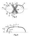
- the assembled liners 12 and 14 serve as a winding mandrel for a load carrying filament winding 60 which progresses in a polar winding pattern about polar openings 62 at a wind angle of ⁇ .
- the liners 12 and 14 define upper and lower domed geodesic surfaces 64 and 66 meeting at a line defining the diameter of the pressure vessel.
- the filament winding 60 comprises winding bands of glass, an aramid, carbon filaments, or the like.
- the winding is conducted in accordance with known polar winding techniques.
- FIG. 4 there is illustrated a geodesic dome profile where no bending loads are permitted in the winding filaments.
- Equation (5) defines the equilibrium dome contour for a first curved surface portion 68, as indicated by the brackets in FIG. 3.
- FIG. 6 there is illustrated the first and second portions of reverse curvature 68 and 72, respectively, joined by the short straight line 74.
- the line 74 has been greatly exaggerated for purposes of clarity.
- X and y axis numerical values may then be calculated from a given tank diameter and a given polar opening diameter. These values may then be programmed into a numerically controlled mold cutting machine according to prior art practices to produce a mold having the described curvature.
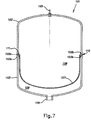
- a diaphragm-expansion tank is marked in general by the reference numeral 101.
- This diaphragm-expansion tank 101 has an upper half shell 102 and a lower half shell 103, which are made of plastic and can, in principle, have any shape. This shape must, however, be chosen so that the two half shells 102 and 103, when pressed together, can be filament-wound with thread-type or belt-type coils, as is shown, for example, in U.S. Patent No. 4,595,037.
- This winding coil is shown only in Figs. 10 and 11, 14 and 15 and is identified by the reference numeral 104.
- the winding 104 is preferably made of fiberglass impregnated with a hardening resin.
- the upper plastic half shell 102 has a hole in the middle into which a gas valve 105 is inserted. Opposite it, in the lower half shell 103, is a pipe connection 106 for connecting to a water line, which leads to an industrial water or hot water system, as is usual with such diaphragm-expansion tanks.
- the inside of the tank is separated by a diaphragm 107, made of an elastomer or the like, into a gas space 108 and a water space 109 with different volumes, which are tightly sealed from one another by the diaphragm 107.
- the gas space 108 is filled through the valve 105 with preliminary pressure, that depends on the purpose for which it is used. In Figs.
- the diaphragm 107 is in the resting position. After the preliminary pressure is added, the diaphragm-whether designed as a half diaphragm or a ball diaphragm--lies on half or all of the inside. Now if the water in the industrial water or hot-water system expands, it can penetrate into the water space 109, and press together the diaphragm 107 in the direction of the gas space 108, whereby the volume of the water space 109 is increased and the volume of the gas space 108 is reduced accordingly.
- the important thing about the diaphragm-expansion tank 101 according to this aspect of the invention is the connecting area between the two half shells 102 and 103 and the type of seal between them.
- the upper half shell 102 has, on its outer edge, a first overlapping leg-shaped section 102a and the lower half shell 103 a corresponding opposite section 103a, so that these two sections 102a and 103a fit together and are centered when the two half shells 102 and 103 are put together.
- both half shells 102 and 103 have leg-shaped areas 102b and 103b on the inside, which form an overlapping slit-shaped receptacle 110, when the two half shells 102 and 103 are together, which is somewhat round in cross section in the example of embodiment in Fig. 7.
- This slit-shaped receptacle 110 is used to hold a ring-shaped sealing element 111, which is an integral part of the diaphragm 107 in the form of embodiment in Fig. 7, i.e., this ring-shaped sealing element 111 is designed in one piece with the diaphragm 107 and forms a sealing and fastening element for the diaphragm 107.
- the diaphragm 107 is preferably first a lid in the area of the receptacle 110 formed by the half shell 103, and then the upper half shell 102 is set down on it in such a way that the two sections 102a and 103a fit together and are centered. In this position, the two half shells 102 and 103 are pressed together and then provided with a coil 104 as known.
- a coil 104 as known.
- Figs. 8 to 15 show other embodiments; the same reference numbers are used as in Fig. 7 for the same parts.
- the half shells 102 and 103 are designed differently in the area where they are connected.
- Section 102a of the upper half shell is designed as a leg 102a that is bent to the inside, while the lower half shell 103 is straight in area 103a and overlaps and fits into area 102a.
- the leg-shaped area 102a of the upper half shell 102 also extends toward the outside in one area 102b, which has a bulge, which along with the assigned area 103b of the lower half shell 103 forms a roughly semicircular receptacle 110 for the sealing element 111, which is in turn an integral part of the diaphragm 107.
- the connecting area between the two half shells 102 and 103 is designed in the same way as in the form of embodiment in Fig. 7. But is inserted into the corresponding receptacle 110 which is not an integral part of the diaphragm.
- This form of embodiment uses a ball diaphragm 107, which is known and was inserted into it through a flange-shaped hole 112 on top of the upper half shell 102 after the diaphragm expansion tank 101 was assembled.
- the ball diaphragm 107' has an attachment edge 107a on its outer end and is pressed between the flange 112 and a flange plate 113, wherein the valve 105 is arranged in the flange plate 113.
- the ball diaphragm 107' alone forms the gas space 108 as known.
- a somewhat different shape was chosen for the sections 102a and 103a and the receptacle 110.
- the overlapping section 102a of the upper half shell 102 here is designed as a leg 102a running diagonally to the inside and the section 103a of the lower half shell 103 is accordingly designed as a leg 103a running diagonally opposite.
- the receptacle 110 for the sealing element 111 of the diaphragm 107 is designed roughly semicircular in this form of embodiment, for which the areas 102b and 103b have a corresponding form, as can be seen in Fig. 10.
- Fig. 11 differs from the one in Fig. 10 basically only in the shape of the receptacle 110.
- the receptacle is not circular or semicircular in cross section, but square, which is achieved by the corresponding design of areas 102b and 103b.
- Section 102a of the upper half shell 102 is designed here as a groove-shaped recess, while the opposite section 103a on the lower half shell is designed as a protruding leg that runs correspondingly.
- the receptacle 110 is also divided and is designed to be roughly round due to the corresponding design of the areas 102b and 103b.
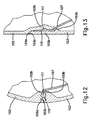
- the form of embodiment in Fig. 13 corresponds largely to the form of embodiment in Fig. 8. Only here, another bulge 103c running around the inside is provided on the lower half shell 103, which makes for even better pressing in of the diaphragm 107.
- section 103a is designed as an overlapping leg, which runs conically and fits into a corresponding groove-shaped receptacle 102a on the upper half shell 102.
- Fig. 14 shows a form of embodiment of a diaphragm expansion tank that corresponds to the embodiment in Fig. 8, with the exception of the area where the two half shells 102 and 103 are connected.
- sections 102a, 103a are designed as outer and inner threads (preferably saw threads) so that the two half shells 102 and 103 can be screwed together easily before winding.
- a guide lip 111a is formed on the attachment edge 111 of the diaphragm 107 forming the sealing element which fits into a receptacle 114 in the half shell 103.
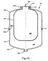
- Fig. 15 shows a form of embodiment that is similar to the one in Fig. 9.
- a single sealing element 111 and a ball diaphragm 107' are provided.
- Sections 102a, 103a of the two half shells 102, 103 are designed as threads, as in the form of embodiment in Fig. 14.
Landscapes
- Engineering & Computer Science (AREA)
- Mechanical Engineering (AREA)
- General Engineering & Computer Science (AREA)
- Filling Or Discharging Of Gas Storage Vessels (AREA)
- Pressure Vessels And Lids Thereof (AREA)
- Yarns And Mechanical Finishing Of Yarns Or Ropes (AREA)
- Artificial Filaments (AREA)
- Separation Using Semi-Permeable Membranes (AREA)
Applications Claiming Priority (4)
| Application Number | Priority Date | Filing Date | Title |
|---|---|---|---|
| DE19506747 | 1995-02-27 | ||
| DE19506747 | 1995-02-27 | ||
| US08/402,920 US5484079A (en) | 1995-03-13 | 1995-03-13 | Hydropneumatic filament-wound pressure vessel |
| US402920 | 2003-03-28 |
Publications (3)
| Publication Number | Publication Date |
|---|---|
| EP0744274A2 true EP0744274A2 (de) | 1996-11-27 |
| EP0744274A3 EP0744274A3 (de) | 1997-01-02 |
| EP0744274B1 EP0744274B1 (de) | 2001-10-04 |
Family
ID=26012837
Family Applications (1)
| Application Number | Title | Priority Date | Filing Date |
|---|---|---|---|
| EP96300917A Expired - Lifetime EP0744274B1 (de) | 1995-02-27 | 1996-02-09 | Hydropneumatischer fasergewickelter Druckbehälter |
Country Status (6)
| Country | Link |
|---|---|
| EP (1) | EP0744274B1 (de) |
| AT (1) | ATE206352T1 (de) |
| DE (1) | DE69615609T2 (de) |
| DK (1) | DK0744274T3 (de) |
| ES (1) | ES2163584T3 (de) |
| PT (1) | PT744274E (de) |
Cited By (10)
| Publication number | Priority date | Publication date | Assignee | Title |
|---|---|---|---|---|
| WO2001084041A1 (de) * | 2000-05-02 | 2001-11-08 | Ludwig Bölkow Stiftung | Tankanlage für aus kleinen bis kleinsten festkörpern bestehendes, mit einem brennbaren gas beladbares schüttgut und einer einrichtung zum entladen des schüttgutes |
| CN100402126C (zh) * | 2006-08-31 | 2008-07-16 | 哈尔滨工业大学 | 金属滤油网多层叠加缠绕成形方法 |
| CN100402914C (zh) * | 2006-08-29 | 2008-07-16 | 哈尔滨工业大学 | 环形气瓶的非测地线缠绕成型方法 |
| ES2400770A1 (es) * | 2011-03-03 | 2013-04-12 | Ikx Hydro, S.L. | Acumulador de presión de membrana intercambiable. |
| CN108692181A (zh) * | 2018-03-28 | 2018-10-23 | 航天材料及工艺研究所 | 一种复合材料气瓶的制备方法 |
| CN110726068A (zh) * | 2019-10-30 | 2020-01-24 | 武汉格罗夫氢能汽车有限公司 | 一种用于氢能汽车的新型储氢瓶 |
| CN113479348A (zh) * | 2021-07-02 | 2021-10-08 | 兰州空间技术物理研究所 | 一种多维度高速飞行能实时高效排放的隔膜密封夹持组件 |
| CN114151716A (zh) * | 2020-09-08 | 2022-03-08 | 本田技研工业株式会社 | 高压容器 |
| CN116447321A (zh) * | 2023-04-25 | 2023-07-18 | 哈尔滨玻璃钢研究院有限公司 | 一种封头开孔碳纤维缠绕压力容器及其成型方法 |
| CN117985350A (zh) * | 2024-04-01 | 2024-05-07 | 西安瑞霖电子科技股份有限公司 | 中隔储箱及其制造方法、具有中隔储箱的储存罐 |
Families Citing this family (1)
| Publication number | Priority date | Publication date | Assignee | Title |
|---|---|---|---|---|
| EP3868543B1 (de) * | 2020-02-20 | 2023-08-16 | Magna Energy Storage Systems GesmbH | Verfahren zur herstellung einer halbschale |
Family Cites Families (12)
| Publication number | Priority date | Publication date | Assignee | Title |
|---|---|---|---|---|
| US2343320A (en) * | 1940-03-18 | 1944-03-07 | Parker Appliance Co | Accumulator |
| US2345124A (en) * | 1941-12-01 | 1944-03-28 | New York Air Brake Co | Accumulator |
| BE617443A (fr) * | 1961-05-30 | 1962-08-31 | Olaer Patent Co | Dispositif et procédé de montage d'un séparateur souple sur un réservoir de pression |
| GB1064590A (en) * | 1964-11-04 | 1967-04-05 | Aerojet General Co | Filament wound pressure vessel |
| FR1493720A (fr) * | 1966-07-21 | 1967-09-01 | Citroen Sa Andre | Membrane élastique pour accumulateur hydraulique |
| FR1554072A (de) * | 1967-06-27 | 1969-01-17 | ||
| DE2048647A1 (de) * | 1970-10-03 | 1972-05-31 | Langen & Co | Druckspeicher |
| GB1431162A (en) * | 1974-04-10 | 1976-04-07 | Sugimura N | Accumulator |
| FR2367982A1 (fr) * | 1976-10-18 | 1978-05-12 | Luchaire Sa | Perfectionnements apportes aux recipients destines a contenir un gaz ou un liquide sous pression |
| FR2499170A1 (fr) * | 1981-02-04 | 1982-08-06 | Leduc Rene Hydro Sa | Procede de fixation d'une membrane souple d'accelerateur oleo-pneumatique |
| FR2540603B1 (fr) * | 1983-02-08 | 1988-04-15 | Olaer Ind Sa | Reservoir de pression a double paroi |
| US4595037A (en) * | 1984-12-14 | 1986-06-17 | Essef Industries, Inc. | Split tank closure and diaphragm assembly |
-
1996
- 1996-02-09 ES ES96300917T patent/ES2163584T3/es not_active Expired - Lifetime
- 1996-02-09 EP EP96300917A patent/EP0744274B1/de not_active Expired - Lifetime
- 1996-02-09 PT PT96300917T patent/PT744274E/pt unknown
- 1996-02-09 DE DE69615609T patent/DE69615609T2/de not_active Expired - Lifetime
- 1996-02-09 AT AT96300917T patent/ATE206352T1/de not_active IP Right Cessation
- 1996-02-09 DK DK96300917T patent/DK0744274T3/da active
Cited By (12)
| Publication number | Priority date | Publication date | Assignee | Title |
|---|---|---|---|---|
| WO2001084041A1 (de) * | 2000-05-02 | 2001-11-08 | Ludwig Bölkow Stiftung | Tankanlage für aus kleinen bis kleinsten festkörpern bestehendes, mit einem brennbaren gas beladbares schüttgut und einer einrichtung zum entladen des schüttgutes |
| CN100402914C (zh) * | 2006-08-29 | 2008-07-16 | 哈尔滨工业大学 | 环形气瓶的非测地线缠绕成型方法 |
| CN100402126C (zh) * | 2006-08-31 | 2008-07-16 | 哈尔滨工业大学 | 金属滤油网多层叠加缠绕成形方法 |
| ES2400770A1 (es) * | 2011-03-03 | 2013-04-12 | Ikx Hydro, S.L. | Acumulador de presión de membrana intercambiable. |
| CN108692181A (zh) * | 2018-03-28 | 2018-10-23 | 航天材料及工艺研究所 | 一种复合材料气瓶的制备方法 |
| CN110726068A (zh) * | 2019-10-30 | 2020-01-24 | 武汉格罗夫氢能汽车有限公司 | 一种用于氢能汽车的新型储氢瓶 |
| CN110726068B (zh) * | 2019-10-30 | 2024-03-08 | 中极氢能汽车(长治)有限公司 | 一种用于氢能汽车的储氢瓶 |
| CN114151716A (zh) * | 2020-09-08 | 2022-03-08 | 本田技研工业株式会社 | 高压容器 |
| CN113479348A (zh) * | 2021-07-02 | 2021-10-08 | 兰州空间技术物理研究所 | 一种多维度高速飞行能实时高效排放的隔膜密封夹持组件 |
| CN116447321A (zh) * | 2023-04-25 | 2023-07-18 | 哈尔滨玻璃钢研究院有限公司 | 一种封头开孔碳纤维缠绕压力容器及其成型方法 |
| CN117985350A (zh) * | 2024-04-01 | 2024-05-07 | 西安瑞霖电子科技股份有限公司 | 中隔储箱及其制造方法、具有中隔储箱的储存罐 |
| CN117985350B (zh) * | 2024-04-01 | 2024-07-05 | 西安瑞霖电子科技股份有限公司 | 中隔储箱及其制造方法、具有中隔储箱的储存罐 |
Also Published As
| Publication number | Publication date |
|---|---|
| ATE206352T1 (de) | 2001-10-15 |
| DK0744274T3 (da) | 2002-01-21 |
| DE69615609D1 (de) | 2001-11-08 |
| EP0744274A3 (de) | 1997-01-02 |
| PT744274E (pt) | 2002-03-28 |
| EP0744274B1 (de) | 2001-10-04 |
| DE69615609T2 (de) | 2002-12-12 |
| ES2163584T3 (es) | 2002-02-01 |
Similar Documents
| Publication | Publication Date | Title |
|---|---|---|
| US4595037A (en) | Split tank closure and diaphragm assembly | |
| EP0647784B1 (de) | Membranbefestigung für einen Membranspeicher | |
| EP0744274A2 (de) | Hydropneumatischer fasergewickelter Druckbehälter | |
| US4765507A (en) | Pressure vessel with an improved sidewall structure | |
| US5526994A (en) | Filament-wound isotensoid pressure vessels having geodesic domes | |
| US5551590A (en) | Non-metallic pressure vessel fitting | |
| US6135308A (en) | Boss for a filament wound pressure vessel | |
| JP4599380B2 (ja) | 高圧容器のシール構造 | |
| KR102484769B1 (ko) | 압력용기용 압력 포트 요소가 있는 폴캡 | |
| US9751689B2 (en) | Pressure vessel system and method | |
| US5938209A (en) | Seal system for fluid pressure vessels | |
| US20050011891A1 (en) | Compressed gas tank for a motor vehicle | |
| KR950014817B1 (ko) | 개량된 측벽 구조물을 갖는 압력 용기 | |
| US5484079A (en) | Hydropneumatic filament-wound pressure vessel | |
| US20070181199A1 (en) | Hydraulic accumulator | |
| US20070062841A1 (en) | Cover body mounting structure of resin container | |
| EP0790411A1 (de) | Korrosionsbeständiges Ausdehnungsgefäss | |
| US12313090B2 (en) | Hydro-pneumatic pressure vessel and diaphragm assembly method | |
| US4234017A (en) | Accumulator device or the like | |
| KR102719092B1 (ko) | 소직경 장축 압력용기 | |
| KR102822009B1 (ko) | 밀봉재 및 캡을 이용한 보스와 라이너의 체결 구조 및 이의 성형 방법 | |
| US11512804B2 (en) | Expansion tank | |
| KR102898323B1 (ko) | 경직성 형상에 대비한 팽창을 위한 주름들 | |
| AU710621B2 (en) | Dual chamber fluid storage vessel | |
| US20050167436A1 (en) | Water heater tank minus bottom cylinder end |
Legal Events
| Date | Code | Title | Description |
|---|---|---|---|
| PUAI | Public reference made under article 153(3) epc to a published international application that has entered the european phase |
Free format text: ORIGINAL CODE: 0009012 |
|
| PUAL | Search report despatched |
Free format text: ORIGINAL CODE: 0009013 |
|
| AK | Designated contracting states |
Kind code of ref document: A2 Designated state(s): AT BE CH DE DK ES FR GB GR IE IT LI LU MC NL PT SE |
|
| AX | Request for extension of the european patent |
Free format text: LT PAYMENT 960220;LV PAYMENT 960220;SI PAYMENT 960220 |
|
| AK | Designated contracting states |
Kind code of ref document: A3 Designated state(s): AT BE CH DE DK ES FR GB GR IE IT LI LU MC NL PT SE |
|
| AX | Request for extension of the european patent |
Free format text: LT PAYMENT 960220;LV PAYMENT 960220;SI PAYMENT 960220 |
|
| 17P | Request for examination filed |
Effective date: 19970701 |
|
| 17Q | First examination report despatched |
Effective date: 19990325 |
|
| GRAG | Despatch of communication of intention to grant |
Free format text: ORIGINAL CODE: EPIDOS AGRA |
|
| GRAG | Despatch of communication of intention to grant |
Free format text: ORIGINAL CODE: EPIDOS AGRA |
|
| GRAH | Despatch of communication of intention to grant a patent |
Free format text: ORIGINAL CODE: EPIDOS IGRA |
|
| GRAG | Despatch of communication of intention to grant |
Free format text: ORIGINAL CODE: EPIDOS AGRA |
|
| GRAH | Despatch of communication of intention to grant a patent |
Free format text: ORIGINAL CODE: EPIDOS IGRA |
|
| GRAH | Despatch of communication of intention to grant a patent |
Free format text: ORIGINAL CODE: EPIDOS IGRA |
|
| GRAA | (expected) grant |
Free format text: ORIGINAL CODE: 0009210 |
|
| AK | Designated contracting states |
Kind code of ref document: B1 Designated state(s): AT BE CH DE DK ES FR GB GR IE IT LI LU MC NL PT SE |
|
| AX | Request for extension of the european patent |
Free format text: LT PAYMENT 19960220;LV PAYMENT 19960220;SI PAYMENT 19960220 |
|
| LTIE | Lt: invalidation of european patent or patent extension | ||
| REF | Corresponds to: |
Ref document number: 206352 Country of ref document: AT Date of ref document: 20011015 Kind code of ref document: T |
|
| REG | Reference to a national code |
Ref country code: CH Ref legal event code: EP |
|
| REF | Corresponds to: |
Ref document number: 69615609 Country of ref document: DE Date of ref document: 20011108 |
|
| REG | Reference to a national code |
Ref country code: IE Ref legal event code: FG4D |
|
| REG | Reference to a national code |
Ref country code: GB Ref legal event code: IF02 |
|
| REG | Reference to a national code |
Ref country code: DK Ref legal event code: T3 |
|
| REG | Reference to a national code |
Ref country code: CH Ref legal event code: NV Representative=s name: A. BRAUN, BRAUN, HERITIER, ESCHMANN AG PATENTANWAE |
|
| REG | Reference to a national code |
Ref country code: ES Ref legal event code: FG2A Ref document number: 2163584 Country of ref document: ES Kind code of ref document: T3 |
|
| ET | Fr: translation filed | ||
| REG | Reference to a national code |
Ref country code: PT Ref legal event code: SC4A Free format text: AVAILABILITY OF NATIONAL TRANSLATION Effective date: 20020104 |
|
| REG | Reference to a national code |
Ref country code: GR Ref legal event code: EP Ref document number: 20010402573 Country of ref document: GR |
|
| PLBE | No opposition filed within time limit |
Free format text: ORIGINAL CODE: 0009261 |
|
| STAA | Information on the status of an ep patent application or granted ep patent |
Free format text: STATUS: NO OPPOSITION FILED WITHIN TIME LIMIT |
|
| 26N | No opposition filed | ||
| REG | Reference to a national code |
Ref country code: CH Ref legal event code: PFA Owner name: ESSEF CORPORATION Free format text: ESSEF CORPORATION#220 PARK DRIVE#CHARDON, OH 44024 (US) -TRANSFER TO- ESSEF CORPORATION#220 PARK DRIVE#CHARDON, OH 44024 (US) |
|
| PGFP | Annual fee paid to national office [announced via postgrant information from national office to epo] |
Ref country code: LU Payment date: 20090203 Year of fee payment: 14 Ref country code: IE Payment date: 20090130 Year of fee payment: 14 Ref country code: DK Payment date: 20090206 Year of fee payment: 14 Ref country code: AT Payment date: 20090226 Year of fee payment: 14 |
|
| PGFP | Annual fee paid to national office [announced via postgrant information from national office to epo] |
Ref country code: PT Payment date: 20090126 Year of fee payment: 14 |
|
| PGFP | Annual fee paid to national office [announced via postgrant information from national office to epo] |
Ref country code: GR Payment date: 20090209 Year of fee payment: 14 Ref country code: CH Payment date: 20090205 Year of fee payment: 14 |
|
| PGFP | Annual fee paid to national office [announced via postgrant information from national office to epo] |
Ref country code: SE Payment date: 20090213 Year of fee payment: 14 |
|
| PGFP | Annual fee paid to national office [announced via postgrant information from national office to epo] |
Ref country code: MC Payment date: 20090224 Year of fee payment: 14 |
|
| REG | Reference to a national code |
Ref country code: CH Ref legal event code: NV Representative=s name: BOVARD AG PATENTANWAELTE |
|
| REG | Reference to a national code |
Ref country code: PT Ref legal event code: MM4A Free format text: LAPSE DUE TO NON-PAYMENT OF FEES Effective date: 20100809 |
|
| REG | Reference to a national code |
Ref country code: CH Ref legal event code: PL |
|
| REG | Reference to a national code |
Ref country code: DK Ref legal event code: EBP |
|
| EUG | Se: european patent has lapsed | ||
| PG25 | Lapsed in a contracting state [announced via postgrant information from national office to epo] |
Ref country code: MC Free format text: LAPSE BECAUSE OF NON-PAYMENT OF DUE FEES Effective date: 20100301 Ref country code: LI Free format text: LAPSE BECAUSE OF NON-PAYMENT OF DUE FEES Effective date: 20100228 Ref country code: CH Free format text: LAPSE BECAUSE OF NON-PAYMENT OF DUE FEES Effective date: 20100228 |
|
| REG | Reference to a national code |
Ref country code: IE Ref legal event code: MM4A |
|
| PG25 | Lapsed in a contracting state [announced via postgrant information from national office to epo] |
Ref country code: AT Free format text: LAPSE BECAUSE OF NON-PAYMENT OF DUE FEES Effective date: 20100209 |
|
| PG25 | Lapsed in a contracting state [announced via postgrant information from national office to epo] |
Ref country code: PT Free format text: LAPSE BECAUSE OF NON-PAYMENT OF DUE FEES Effective date: 20100809 Ref country code: IE Free format text: LAPSE BECAUSE OF NON-PAYMENT OF DUE FEES Effective date: 20100209 Ref country code: DK Free format text: LAPSE BECAUSE OF NON-PAYMENT OF DUE FEES Effective date: 20100228 |
|
| PGFP | Annual fee paid to national office [announced via postgrant information from national office to epo] |
Ref country code: IT Payment date: 20120227 Year of fee payment: 17 |
|
| PG25 | Lapsed in a contracting state [announced via postgrant information from national office to epo] |
Ref country code: LU Free format text: LAPSE BECAUSE OF NON-PAYMENT OF DUE FEES Effective date: 20100209 Ref country code: SE Free format text: LAPSE BECAUSE OF NON-PAYMENT OF DUE FEES Effective date: 20100210 |
|
| PGFP | Annual fee paid to national office [announced via postgrant information from national office to epo] |
Ref country code: FR Payment date: 20130301 Year of fee payment: 18 Ref country code: DE Payment date: 20130219 Year of fee payment: 18 Ref country code: GB Payment date: 20130218 Year of fee payment: 18 Ref country code: ES Payment date: 20130218 Year of fee payment: 18 |
|
| PGFP | Annual fee paid to national office [announced via postgrant information from national office to epo] |
Ref country code: BE Payment date: 20130220 Year of fee payment: 18 Ref country code: NL Payment date: 20130219 Year of fee payment: 18 |
|
| BERE | Be: lapsed |
Owner name: *ESSEF CORP. Effective date: 20140228 |
|
| REG | Reference to a national code |
Ref country code: DE Ref legal event code: R119 Ref document number: 69615609 Country of ref document: DE |
|
| REG | Reference to a national code |
Ref country code: NL Ref legal event code: V1 Effective date: 20140901 |
|
| GBPC | Gb: european patent ceased through non-payment of renewal fee |
Effective date: 20140209 |
|
| PG25 | Lapsed in a contracting state [announced via postgrant information from national office to epo] |
Ref country code: NL Free format text: LAPSE BECAUSE OF NON-PAYMENT OF DUE FEES Effective date: 20140901 |
|
| REG | Reference to a national code |
Ref country code: FR Ref legal event code: ST Effective date: 20141031 |
|
| REG | Reference to a national code |
Ref country code: DE Ref legal event code: R119 Ref document number: 69615609 Country of ref document: DE Effective date: 20140902 |
|
| PG25 | Lapsed in a contracting state [announced via postgrant information from national office to epo] |
Ref country code: DE Free format text: LAPSE BECAUSE OF NON-PAYMENT OF DUE FEES Effective date: 20140902 Ref country code: FR Free format text: LAPSE BECAUSE OF NON-PAYMENT OF DUE FEES Effective date: 20140228 Ref country code: GB Free format text: LAPSE BECAUSE OF NON-PAYMENT OF DUE FEES Effective date: 20140209 Ref country code: BE Free format text: LAPSE BECAUSE OF NON-PAYMENT OF DUE FEES Effective date: 20140228 |
|
| REG | Reference to a national code |
Ref country code: ES Ref legal event code: FD2A Effective date: 20150327 |
|
| PG25 | Lapsed in a contracting state [announced via postgrant information from national office to epo] |
Ref country code: ES Free format text: LAPSE BECAUSE OF NON-PAYMENT OF DUE FEES Effective date: 20140210 |
|
| PG25 | Lapsed in a contracting state [announced via postgrant information from national office to epo] |
Ref country code: IT Free format text: LAPSE BECAUSE OF NON-PAYMENT OF DUE FEES Effective date: 20140209 |