EP0744275A2 - Verfahren zur Herstellung eines Farbrollers - Google Patents
Verfahren zur Herstellung eines Farbrollers Download PDFInfo
- Publication number
- EP0744275A2 EP0744275A2 EP95401652A EP95401652A EP0744275A2 EP 0744275 A2 EP0744275 A2 EP 0744275A2 EP 95401652 A EP95401652 A EP 95401652A EP 95401652 A EP95401652 A EP 95401652A EP 0744275 A2 EP0744275 A2 EP 0744275A2
- Authority
- EP
- European Patent Office
- Prior art keywords
- core
- strip
- mandrel
- wound
- polypropylene
- Prior art date
- Legal status (The legal status is an assumption and is not a legal conclusion. Google has not performed a legal analysis and makes no representation as to the accuracy of the status listed.)
- Granted
Links
- 239000003973 paint Substances 0.000 title claims abstract description 27
- 238000004519 manufacturing process Methods 0.000 title claims description 6
- 239000004744 fabric Substances 0.000 claims abstract description 32
- 239000000853 adhesive Substances 0.000 claims abstract description 25
- 230000001070 adhesive effect Effects 0.000 claims abstract description 25
- 239000012815 thermoplastic material Substances 0.000 claims abstract description 16
- 238000004804 winding Methods 0.000 claims abstract description 10
- -1 polypropylene Polymers 0.000 claims description 46
- 239000004743 Polypropylene Substances 0.000 claims description 45
- 229920001155 polypropylene Polymers 0.000 claims description 45
- 239000007788 liquid Substances 0.000 claims description 27
- 238000000034 method Methods 0.000 claims description 23
- 239000000463 material Substances 0.000 claims description 9
- 229920000728 polyester Polymers 0.000 claims description 6
- 229920001169 thermoplastic Polymers 0.000 abstract description 14
- 239000004416 thermosoftening plastic Substances 0.000 abstract description 14
- 239000002904 solvent Substances 0.000 description 9
- 239000000123 paper Substances 0.000 description 6
- 239000011248 coating agent Substances 0.000 description 5
- 238000000576 coating method Methods 0.000 description 5
- 238000005520 cutting process Methods 0.000 description 5
- 238000000926 separation method Methods 0.000 description 5
- 239000012790 adhesive layer Substances 0.000 description 4
- 230000003466 anti-cipated effect Effects 0.000 description 4
- 239000011093 chipboard Substances 0.000 description 4
- 238000010438 heat treatment Methods 0.000 description 4
- 239000003292 glue Substances 0.000 description 3
- 239000002184 metal Substances 0.000 description 3
- 239000010410 layer Substances 0.000 description 2
- 238000012986 modification Methods 0.000 description 2
- 230000004048 modification Effects 0.000 description 2
- ISWSIDIOOBJBQZ-UHFFFAOYSA-N phenol group Chemical group C1(=CC=CC=C1)O ISWSIDIOOBJBQZ-UHFFFAOYSA-N 0.000 description 2
- 239000004033 plastic Substances 0.000 description 2
- 241000779819 Syncarpia glomulifera Species 0.000 description 1
- 239000004809 Teflon Substances 0.000 description 1
- 229920006362 Teflon® Polymers 0.000 description 1
- 230000003213 activating effect Effects 0.000 description 1
- 238000010420 art technique Methods 0.000 description 1
- 150000001875 compounds Chemical class 0.000 description 1
- 238000010276 construction Methods 0.000 description 1
- 238000001816 cooling Methods 0.000 description 1
- 239000000835 fiber Substances 0.000 description 1
- 239000012943 hotmelt Substances 0.000 description 1
- 238000007654 immersion Methods 0.000 description 1
- 229910052500 inorganic mineral Inorganic materials 0.000 description 1
- 238000009434 installation Methods 0.000 description 1
- 238000005304 joining Methods 0.000 description 1
- 239000011707 mineral Substances 0.000 description 1
- 239000001739 pinus spp. Substances 0.000 description 1
- 230000002035 prolonged effect Effects 0.000 description 1
- 235000015096 spirit Nutrition 0.000 description 1
- 229940036248 turpentine Drugs 0.000 description 1
- XLYOFNOQVPJJNP-UHFFFAOYSA-N water Substances O XLYOFNOQVPJJNP-UHFFFAOYSA-N 0.000 description 1
- 210000002268 wool Anatomy 0.000 description 1
Images

Classifications
-
- B—PERFORMING OPERATIONS; TRANSPORTING
- B05—SPRAYING OR ATOMISING IN GENERAL; APPLYING FLUENT MATERIALS TO SURFACES, IN GENERAL
- B05C—APPARATUS FOR APPLYING FLUENT MATERIALS TO SURFACES, IN GENERAL
- B05C17/00—Hand tools or apparatus using hand held tools, for applying liquids or other fluent materials to, for spreading applied liquids or other fluent materials on, or for partially removing applied liquids or other fluent materials from, surfaces
- B05C17/02—Rollers ; Hand tools comprising coating rollers or coating endless belts
- B05C17/0207—Rollers ; Hand tools comprising coating rollers or coating endless belts characterised by the cover, e.g. cover material or structure, special surface for producing patterns
-
- B—PERFORMING OPERATIONS; TRANSPORTING
- B29—WORKING OF PLASTICS; WORKING OF SUBSTANCES IN A PLASTIC STATE IN GENERAL
- B29C—SHAPING OR JOINING OF PLASTICS; SHAPING OF MATERIAL IN A PLASTIC STATE, NOT OTHERWISE PROVIDED FOR; AFTER-TREATMENT OF THE SHAPED PRODUCTS, e.g. REPAIRING
- B29C53/00—Shaping by bending, folding, twisting, straightening or flattening; Apparatus therefor
- B29C53/56—Winding and joining, e.g. winding spirally
- B29C53/58—Winding and joining, e.g. winding spirally helically
- B29C53/60—Winding and joining, e.g. winding spirally helically using internal forming surfaces, e.g. mandrels
- B29C53/62—Winding and joining, e.g. winding spirally helically using internal forming surfaces, e.g. mandrels rotatable about the winding axis
-
- B—PERFORMING OPERATIONS; TRANSPORTING
- B29—WORKING OF PLASTICS; WORKING OF SUBSTANCES IN A PLASTIC STATE IN GENERAL
- B29C—SHAPING OR JOINING OF PLASTICS; SHAPING OF MATERIAL IN A PLASTIC STATE, NOT OTHERWISE PROVIDED FOR; AFTER-TREATMENT OF THE SHAPED PRODUCTS, e.g. REPAIRING
- B29C53/00—Shaping by bending, folding, twisting, straightening or flattening; Apparatus therefor
- B29C53/80—Component parts, details or accessories; Auxiliary operations
- B29C53/82—Cores or mandrels
- B29C53/821—Mandrels especially adapted for winding and joining
- B29C53/822—Single use mandrels, e.g. destructible, becoming part of the wound articles
-
- B—PERFORMING OPERATIONS; TRANSPORTING
- B29—WORKING OF PLASTICS; WORKING OF SUBSTANCES IN A PLASTIC STATE IN GENERAL
- B29C—SHAPING OR JOINING OF PLASTICS; SHAPING OF MATERIAL IN A PLASTIC STATE, NOT OTHERWISE PROVIDED FOR; AFTER-TREATMENT OF THE SHAPED PRODUCTS, e.g. REPAIRING
- B29C63/00—Lining or sheathing, i.e. applying preformed layers or sheathings of plastics; Apparatus therefor
- B29C63/02—Lining or sheathing, i.e. applying preformed layers or sheathings of plastics; Apparatus therefor using sheet or web-like material
- B29C63/04—Lining or sheathing, i.e. applying preformed layers or sheathings of plastics; Apparatus therefor using sheet or web-like material by folding, winding, bending or the like
- B29C63/08—Lining or sheathing, i.e. applying preformed layers or sheathings of plastics; Apparatus therefor using sheet or web-like material by folding, winding, bending or the like by winding helically
- B29C63/10—Lining or sheathing, i.e. applying preformed layers or sheathings of plastics; Apparatus therefor using sheet or web-like material by folding, winding, bending or the like by winding helically around tubular articles
-
- B—PERFORMING OPERATIONS; TRANSPORTING
- B29—WORKING OF PLASTICS; WORKING OF SUBSTANCES IN A PLASTIC STATE IN GENERAL
- B29C—SHAPING OR JOINING OF PLASTICS; SHAPING OF MATERIAL IN A PLASTIC STATE, NOT OTHERWISE PROVIDED FOR; AFTER-TREATMENT OF THE SHAPED PRODUCTS, e.g. REPAIRING
- B29C63/00—Lining or sheathing, i.e. applying preformed layers or sheathings of plastics; Apparatus therefor
- B29C63/02—Lining or sheathing, i.e. applying preformed layers or sheathings of plastics; Apparatus therefor using sheet or web-like material
- B29C63/04—Lining or sheathing, i.e. applying preformed layers or sheathings of plastics; Apparatus therefor using sheet or web-like material by folding, winding, bending or the like
- B29C63/08—Lining or sheathing, i.e. applying preformed layers or sheathings of plastics; Apparatus therefor using sheet or web-like material by folding, winding, bending or the like by winding helically
- B29C63/10—Lining or sheathing, i.e. applying preformed layers or sheathings of plastics; Apparatus therefor using sheet or web-like material by folding, winding, bending or the like by winding helically around tubular articles
- B29C63/105—Lining or sheathing, i.e. applying preformed layers or sheathings of plastics; Apparatus therefor using sheet or web-like material by folding, winding, bending or the like by winding helically around tubular articles continuously
-
- B—PERFORMING OPERATIONS; TRANSPORTING
- B29—WORKING OF PLASTICS; WORKING OF SUBSTANCES IN A PLASTIC STATE IN GENERAL
- B29D—PRODUCING PARTICULAR ARTICLES FROM PLASTICS OR FROM SUBSTANCES IN A PLASTIC STATE
- B29D99/00—Subject matter not provided for in other groups of this subclass
- B29D99/0032—Producing rolling bodies, e.g. rollers, wheels, pulleys or pinions
- B29D99/0035—Producing rolling bodies, e.g. rollers, wheels, pulleys or pinions rollers or cylinders having an axial length of several times the diameter, e.g. for embossing, pressing, or printing
-
- B—PERFORMING OPERATIONS; TRANSPORTING
- B29—WORKING OF PLASTICS; WORKING OF SUBSTANCES IN A PLASTIC STATE IN GENERAL
- B29C—SHAPING OR JOINING OF PLASTICS; SHAPING OF MATERIAL IN A PLASTIC STATE, NOT OTHERWISE PROVIDED FOR; AFTER-TREATMENT OF THE SHAPED PRODUCTS, e.g. REPAIRING
- B29C2793/00—Shaping techniques involving a cutting or machining operation
- B29C2793/009—Shaping techniques involving a cutting or machining operation after shaping
-
- B—PERFORMING OPERATIONS; TRANSPORTING
- B29—WORKING OF PLASTICS; WORKING OF SUBSTANCES IN A PLASTIC STATE IN GENERAL
- B29K—INDEXING SCHEME ASSOCIATED WITH SUBCLASSES B29B, B29C OR B29D, RELATING TO MOULDING MATERIALS OR TO MATERIALS FOR MOULDS, REINFORCEMENTS, FILLERS OR PREFORMED PARTS, e.g. INSERTS
- B29K2023/00—Use of polyalkenes or derivatives thereof as moulding material
- B29K2023/10—Polymers of propylene
- B29K2023/12—PP, i.e. polypropylene
-
- B—PERFORMING OPERATIONS; TRANSPORTING
- B29—WORKING OF PLASTICS; WORKING OF SUBSTANCES IN A PLASTIC STATE IN GENERAL
- B29K—INDEXING SCHEME ASSOCIATED WITH SUBCLASSES B29B, B29C OR B29D, RELATING TO MOULDING MATERIALS OR TO MATERIALS FOR MOULDS, REINFORCEMENTS, FILLERS OR PREFORMED PARTS, e.g. INSERTS
- B29K2101/00—Use of unspecified macromolecular compounds as moulding material
- B29K2101/12—Thermoplastic materials
-
- B—PERFORMING OPERATIONS; TRANSPORTING
- B29—WORKING OF PLASTICS; WORKING OF SUBSTANCES IN A PLASTIC STATE IN GENERAL
- B29L—INDEXING SCHEME ASSOCIATED WITH SUBCLASS B29C, RELATING TO PARTICULAR ARTICLES
- B29L2031/00—Other particular articles
- B29L2031/32—Wheels, pinions, pulleys, castors or rollers, Rims
- B29L2031/324—Rollers or cylinders having an axial length of several times the diameter, e.g. embossing, pressing or printing
-
- B—PERFORMING OPERATIONS; TRANSPORTING
- B29—WORKING OF PLASTICS; WORKING OF SUBSTANCES IN A PLASTIC STATE IN GENERAL
- B29L—INDEXING SCHEME ASSOCIATED WITH SUBCLASS B29C, RELATING TO PARTICULAR ARTICLES
- B29L2031/00—Other particular articles
- B29L2031/32—Wheels, pinions, pulleys, castors or rollers, Rims
- B29L2031/328—Paint rollers
-
- Y—GENERAL TAGGING OF NEW TECHNOLOGICAL DEVELOPMENTS; GENERAL TAGGING OF CROSS-SECTIONAL TECHNOLOGIES SPANNING OVER SEVERAL SECTIONS OF THE IPC; TECHNICAL SUBJECTS COVERED BY FORMER USPC CROSS-REFERENCE ART COLLECTIONS [XRACs] AND DIGESTS
- Y10—TECHNICAL SUBJECTS COVERED BY FORMER USPC
- Y10T—TECHNICAL SUBJECTS COVERED BY FORMER US CLASSIFICATION
- Y10T29/00—Metal working
- Y10T29/49—Method of mechanical manufacture
- Y10T29/49544—Roller making
- Y10T29/49547—Assembling preformed components
- Y10T29/49549—Work contacting surface element assembled to core
-
- Y—GENERAL TAGGING OF NEW TECHNOLOGICAL DEVELOPMENTS; GENERAL TAGGING OF CROSS-SECTIONAL TECHNOLOGIES SPANNING OVER SEVERAL SECTIONS OF THE IPC; TECHNICAL SUBJECTS COVERED BY FORMER USPC CROSS-REFERENCE ART COLLECTIONS [XRACs] AND DIGESTS
- Y10—TECHNICAL SUBJECTS COVERED BY FORMER USPC
- Y10T—TECHNICAL SUBJECTS COVERED BY FORMER US CLASSIFICATION
- Y10T29/00—Metal working
- Y10T29/49—Method of mechanical manufacture
- Y10T29/49544—Roller making
- Y10T29/49547—Assembling preformed components
- Y10T29/49549—Work contacting surface element assembled to core
- Y10T29/49551—Work contacting surface wound about core
-
- Y—GENERAL TAGGING OF NEW TECHNOLOGICAL DEVELOPMENTS; GENERAL TAGGING OF CROSS-SECTIONAL TECHNOLOGIES SPANNING OVER SEVERAL SECTIONS OF THE IPC; TECHNICAL SUBJECTS COVERED BY FORMER USPC CROSS-REFERENCE ART COLLECTIONS [XRACs] AND DIGESTS
- Y10—TECHNICAL SUBJECTS COVERED BY FORMER USPC
- Y10T—TECHNICAL SUBJECTS COVERED BY FORMER US CLASSIFICATION
- Y10T29/00—Metal working
- Y10T29/49—Method of mechanical manufacture
- Y10T29/4998—Combined manufacture including applying or shaping of fluent material
- Y10T29/49982—Coating
Definitions
- This invention pertains to a method and apparatus for making paint rollers of the type used for applying paint to walls and the like.
- Paint rollers are widely used by professionals and amateurs for applying paint to walls, ceilings, and other surfaces.
- the roller is used with an applicator having a handle terminating in a rotatable member to which the roller is secured.
- the roller itself comprises two main components, a core and a paint absorbing cover.
- the core is typically paper or plastic, while the cover may be wool, polyester, etc.
- the methods used for forming the core and for securing the cover to the core determine whether the roller is reusable, as paint solvents such as turpentine, mineral spirits, etc. are also solvents for many adhesives.
- paint rollers are manufactured using an automated assembly line.
- a disposable roller is made by first feeding three chipboard paper strips at an angle to a mandrel for overlapping, helical winding to form an endless, belt driven core.
- the paper strips are supplied in rolls for mounting on spindles for continuous feeding, and a continuous adhesive stream is applied to the outer surfaces of the strips as they feed off the rollers such that the strips adhere together as they are helically wound to form the core.
- the adhesive is not critical, and an inexpensive adhesive, such as a water soluble white glue, is used.
- the endless core As the endless core is belt driven down the line, it reaches a second adhesive applicator where a continuous adhesive stream is applied to the outer surface of the core after which a continuous strip of the cover material, such as polyester, is helically wound on to the core where it is secured by the adhesive.
- a continuous adhesive stream is applied to the outer surface of the core after which a continuous strip of the cover material, such as polyester, is helically wound on to the core where it is secured by the adhesive.
- rollers thus formed may not be reused, as the adhesive which binds the core and secures the cover to the core is soluble in paint solvents, and consequently any attempt to clean the roller leads to unravelling of the core and separation of the core from the cover.
- thermosettlng glue is used for securing the core.
- the core is heated in a multi-stage infrared heater, after which a hot melt glue is applied to the core's outer surface.
- the rollers are then completed as before, i.e. by helically winding the fabric cover on to the core and then cutting the resulting endless roller into usable lengths.
- reusable cores formed in this manner require a longer assembly line, due to the need of a heater, and because the phenolic must be heated to a predetermined temperature, there is an obvious trade off between the number of heater stages and the speed of the line.
- the resulting rollers are termed reusable because they do not separate when placed in paint solvents, prolonged exposure to such solvents, e.g. about two days, does result in separation.
- the Garcia roller is formed using a core comprised of preformed thermoplastic (e.g. polypropylene) tubular stock.
- a movable carriage mounted at an angle to the spindle feeds a continuous strip of fabric, the carriage moving parallel to the spindle in timed relation to its rotation so that the fabric strip is wound on the plastic core in a tight helix.
- a heat source for heat-softening the thermoplastic core just in advance of the point where the fabric strip is applied, such that the fabric is bonded to the core as it is wound thereon.
- One advantage of the roller disclosed in the Garcia patent is that it is reusable, as the bond formed between cover and core is a strong one not subject to separation from exposure to paint solvents.
- Another advantage is that the manufacturing process does not require the application of an adhesive to bond the cover to the core.
- drawbacks For one, while prior art techniques use rolls of, e.g., chipboard or paper, the Garcia process requires preformed thermoplastic tubular cores which are considerably bulkier than rolls, more expensive to transport, and more difficult to handle.
- Another drawback is the anticipated speed limit of the Garcia process dictated by the necessity that the heater, which advances along the core just in front of the fabric strip, move slow enough to insure softening of the thermoplastic core, in the absence of which the fabric cover will not bond.
- paint rollers are formed from one or more strips of thermoplastic material, preferably polypropylene, wound together in overlapping relation about a stationary mandrel to form a core, to which a cover is applied.
- the thermoplastic strips comprising the core are bonded together by a thermoplastic material, again preferably polypropylene which is applied to the strips in liquid form, as by sufficiently heating the polypropylene in a demand melter to liquefy it, and then feeding it to the strips via feed tubes extending from the melter.
- the thermoplastic strips are rapidly bonded to each other to form the core as the liquid polypropylene cools and sets.
- an adhesive preferably additional liquid polypropylene
- a fabric cover comprised for example of polyester
- the resulting roller is reusable owing to the strength of the polypropylene bonding, which resists separation upon immersion in paint solvents, even with exposure over several days.
- thermoplastic is applied to a belt which transfers the rapid setting liquefied thermoplastic to the stationary mandril. Since the liquefied thermoplastic does not stick to the metal surface of the mandrel, a coating forms about the mandrel. This thermoplastic coating sets to form the core.
- the paint rollers are formed in a manner similar to that of the first embodiment except that the step of preforming the core by applying adhesive to the helically wound thermoplastic strip or strips is eliminated.
- the paint roller is made by helically winding a thermoplastic strip around a mandril, applying a layer of liquified adhesive onto the outer surface of the wound strip and then helically wrapping a fabric cover about the wound strip to thereby form a paint roller.
- this embodiment is more efficient and less costly as it requires oily a single application of liquid adhesive.
- the rollers of the present invention are preferably formed Using an assembly line process, which is simplified by the fact that the process for making the paint rollers of the invention uses many components common to prior art systems for making paint rollers. Furthermore, when an assembly line process is used, it is expected to be quite fast, as the polypropylene may be liquified at a location remote from the assembly line, whereby the process need not be slowed to accommodate on-line heating. Furthermore, because of the rapidity with which liquid polypropylene sets under ambient conditions, it is anticipated that the endless roller formed on the assembly line may be cut almost immediately after the fabric cover is applied, thereby allowing the assembly line to be kept quite short while still yielding a strongly bonded, reusable roller.
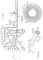
- an apparatus suitable for making rollers in accordance with a first embodiment of the present invention is generally designated as 10.
- One advantage of the apparatus 10 is that it incorporates several components common to widely used prior art systems, and hence is easily retrofitted. These components include a housing 12 supporting a stationary mandril 14, a driven belt 16 wound about the formed core 18 for advancing it to the right in FIG. 1, a flyaway cutter 20 for cutting the formed endless roller 22 into usable lengths, and journaled spindles (not shown) for supporting the three rolls (also not shown) from which the strips 24, 26, 28 and 30 are drawn.
- thermoplastic material preferably liquid polypropylene 34
- applicators 36, 38 and 40 connected by, respectively, feed tubes 42, 44 and 46 to heater 32 for applying the liquid polypropylene at predetermined points in the process, and the use of thermoplastic strips 24, 26 and 28, again preferably polypropylene, to form the core 18.
- An advantage of the invention is that it employs rolls of polypropylene strips which are easy to handle and readily substituted for the rolls of chipboard and paper strips common in prior art processes.
- three polypropylene strips 24, 26 and 28 are fed at an angle to the mandril 14, two from one side and one from the other.
- the free ends of the strips 24, 26 and 28, which are typically 68mm (2 11/16"), 70mm (2 3/4") and 71mm (2 13/16") wide, are manually wound about the mandrel 14 until they extend beyond the belt 16, at which point the belt is tightly wrapped about the strips and driven by activating driven wheel 48, whereupon the belt advances the formed core 18 to the right in FIG. 1 thereby continuously pulling fresh lengths of the polypropylene strips 24, 26 and 28 onto the stationary mandrel 14.
- the strip 24 is fed over the mandrel 14 and the strips 26, 28 are fed under the mandril such that all three strips are advanced to the right in FIG. 1 by the rotation of the belt 16, and preferably the strips 24, 26 and 28 are wound in tight helical paths.
- the applicators 36, 38 apply liquid polypropylene from the demand melter 32 to the outer surfaces of the strips 26, 28 just before they are wound on the mandril 14.
- the demand melter is set to maintain its interior at a temperature sufficiently high to insure that the polypropylene therein is in liquid form.
- the liquid polypropylene is disposed between the overlapping strips, and because the strips are also comprised of polypropylene, the overlapping strips are rapidly bonded to each other as the liquid polypropylene cools and sets, thereby forming an integral endless core 18.
- the fabric cover 30 which may comprise any of the conventional materials now in use, such as polyester, is wound onto the core 18, whereupon it is rapidly bonded to the core 18 as liquid polypropylene cools and sets. Again, because the core is also formed of polypropylene, the strong bond is formed between the core 18 and the fabric cover 30. It will be appreciated that in accordance with known techniques, winding of the fabric cover 30 onto the core 18 is started manually, just like the strips 24, 26 and 28, and that fresh lengths of the fabric strip 30 are then continuously pulled onto the core 18 by the advancement of the core 18 to the right as effected by the belt 16. Again, the cover strip 30 is preferably wound in a tight helical path about the core.
- the flyaway cutter for cutting the endless roller 22 may be positioned quite close to the ontake of the fabric cover 30.
- the actual position of the flyaway cutter 20 can, of course, be adjusted as necessary to insure that the cutting operation is not effected before the bonds set.
- the flyaway cutter may be adjusted to cut the endless roller 22 into 163cm (64") stock, which may then be recut to the usual 18cm (7") and 23cm (9") sizes.
- a finished roller 50 in accordance with the invention is shown in FIG. 2, and in cross-section in FIG. 3.
- the roller 50 may be used in the same manner as prior art rollers, namely, as a replacement element or, with the addition of end pieces 52 and a handle 54, as part of a complete roller assembly.
- 56 represents the polypropylene bond joining the fabric cover 30 to the core 18. Because polypropylene bonds are not soluble in paint solvents, the rollers 50 produced in accordance with the invention are reusable. Indeed, because the core 18 itself comprises polypropylene, the roller 50 defines a substantially integral assembly, and it is expected that separation of the fabric 30 from the core 18 will not occur even if the roller is exposed to a paint solvent over a period of several days.
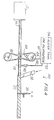
- a second embodiment of an apparatus in accordance with the present invention is generally designated at 60.
- strips 24, 26 and 28, feed tubes 42, 44 and applicators 36, 38 of the apparatus 10 of FIG. 1 have all been eliminated from apparatus 60.
- a feed tube 62 and an applicator 64 feed liquefied polypropylene 34 from heater tank 32 for application to driven belt 16.
- the driven belt 16 is formed of a material such as rubber or teflon compound to which liquid polypropylene 34 does not adhere.
- Driven belt 16 is tightly wrapped around mandrel 14 such that the liquid polypropylene 34 applied to belt 16 is transferred to mandrel 14 by driven belt 16.
- Mandrel 14 is preferably composed of a suitable metal.
- the liquid polypropylene 34 When transferred to mandrel 14 the liquid polypropylene 34 forms a coating thereabout, but does not adhere to the stationary mandril, which is formed of metal.
- the coating is applied evenly about the mandrel as the belt 16 rotates thereabout.
- the coating sets rapidly to form a core 18 which is then continuously advanced to the right by the rotational motion of the belt 16.
- Applicator 40 located preferably 12-18 inches from driven belt 16, applies liquid polypropylene to core 18 in the same manner and for the same purpose as in the apparatus 10 of FIG. 1.
- the invention provides several manufacturing advantages. For one, because of the rapidity with which the polypropylene bonds set, the assembly line can be kept quite short, with the flyaway cutter, the final component on the line, positioned close to the ontake of fabric strip 30. Also, because the polypropylene is preheated to a liquid state in the heater 32, which may be remotely located, there is no need for a heating element in proximity to the assembly line, and consequently the line need not be slowed to accommodate on-line heating. Therefore, it is anticipated that the line can be run quite fast, thereby increasing production and reducing unit cost.
- the method of the invention forms the core and cover from strips, just like the prior art methods, and therefore is easily retrofitted to existing systems using several of their components which, of course, is less expensive than a new installation. Also, as compared with those prior art systems which utilize prefabricated tubular stock for the roller core, the present invention's reliance on polypropylene strips is superior, as strips, which come in rolls, are less bulky and easier to handle. Their lesser bulk also reduces transportation costs.
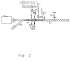
- a flocking head 65 may be used to apply a suitable cover material, such as blown-on fibers, to core 18.
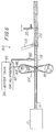
- the step of applying adhesive to the strip or strips 24 prior to the step of winding the strip 24 about the mandrel 14 is eliminated. Rather, the adhesive is applied only after the step 24 is wound on the mandrel 14 and before the step of wrapping the fabric cover strip 30 onto the wound strip 24.
- a single strip 24 is helically wound about the stationary mandrel 14.
- the wound strip 24 is then advanced along the longitudinal axis of the mandrel 14 by the traction force applied by the belt 16.
- the strip 24 is helically wound or wrapped about the mandrel 14 with successive turns in a closely-spaced manner, though it is also contemplated that adjacent edges may be abutting or overlapping.
- the strip 24 is made of a thermoplastic material such as, for example, polypropylene.
- the wound strip 24 is advanced along the longitudinal axis of the mandrel 14 to a position, preferably downstream from the driven belt 16, where a fabric cover strip 30 is applied.
- a fabric cover strip 30 Prior to the application of the fabric cover strip 30, the applicator 40 applies a layer of adhesive such as, for example, a liquid thermoplastic material, to the outer surface of the wound strip 24.
- the liquid thermoplastic material is preferably polypropylene.
- the roller 22 is then formed by helically winding or wrapping the fabric strip 30 over the adhesive layer and about the outer surface of the wound strip 24 with sufficient tensile force so that the fabric cover 30 lays smoothly over the adhesive layer.
- the adhesive layer is of uniform thickness.
- the roller 22 may be cut into desirable lengths by a cutting device such as, for example, a flyaway cutter disposed proximate thereto.
- a cutting device such as, for example, a flyaway cutter disposed proximate thereto.
- the paint roller 50 formed in accordance with this embodiment is an integral roller having the same advantageous characteristics attributable to rollers manufactured according to the other embodiments described herein.
- the entire roller 22 is formed in a single step as the fabric cover 30 is wrapped about the wound strip 24. That is, there is no need to provide a formed core and then wrap the fabric about the formed core. Rather, the entire roller 22 including the core is fabricated in a single step as the fabric is wound about the adhesively coated wound strip 24.
- the roller 22 comprises a wound polypropylene strip 24 having a thickness in the range of about 0.5 to 0.75mm (0.020 inch to 0.030 inch) ; an adhesive layer of polypropylene having a thickness in the range of about 0.01 to 0.02mm (0.005 inch to 0.010 inch); and a fabric cover 30 made of polyester having any suitable thickness.
- the apparatus according to this embodiment requires only one applicator 40 and one feed tube 46. Therefore, feed tubes 42, 44 and applicators 36 and 38 used in the embodiment of FIG. 1 are eliminated.
Landscapes
- Engineering & Computer Science (AREA)
- Mechanical Engineering (AREA)
- Manufacturing & Machinery (AREA)
- Rolls And Other Rotary Bodies (AREA)
- Coating Apparatus (AREA)
- Application Of Or Painting With Fluid Materials (AREA)
Applications Claiming Priority (2)
| Application Number | Priority Date | Filing Date | Title |
|---|---|---|---|
| US447536 | 1995-05-24 | ||
| US08/447,536 US5572790A (en) | 1989-08-15 | 1995-05-24 | Method of making a paint roller |
Publications (3)
| Publication Number | Publication Date |
|---|---|
| EP0744275A2 true EP0744275A2 (de) | 1996-11-27 |
| EP0744275A3 EP0744275A3 (de) | 1997-11-19 |
| EP0744275B1 EP0744275B1 (de) | 2002-01-02 |
Family
ID=23776750
Family Applications (1)
| Application Number | Title | Priority Date | Filing Date |
|---|---|---|---|
| EP95401652A Expired - Lifetime EP0744275B1 (de) | 1995-05-24 | 1995-07-07 | Verfahren zur Herstellung eines Farbrollers |
Country Status (6)
| Country | Link |
|---|---|
| US (1) | US5572790A (de) |
| EP (1) | EP0744275B1 (de) |
| AT (1) | ATE211436T1 (de) |
| AU (1) | AU3305095A (de) |
| CA (1) | CA2153139C (de) |
| DE (1) | DE69524863T2 (de) |
Cited By (9)
| Publication number | Priority date | Publication date | Assignee | Title |
|---|---|---|---|---|
| WO2000026456A1 (en) * | 1998-11-04 | 2000-05-11 | E.I. Du Pont De Nemours And Company | Paint roller and method of making same using continuous yarn tuftstrings |
| US6159134A (en) * | 1999-05-04 | 2000-12-12 | Sekar; Chandra | Methods for manufacturing a paint roller with integrated core and cover |
| US6324717B1 (en) | 1999-11-29 | 2001-12-04 | Chandra Sekar | Paint roller with finished edge and method for making same |
| US6539999B2 (en) * | 2001-02-19 | 2003-04-01 | Newell Operating Company | Apparatus and method for making variable paint roller covers |
| EP2105211A3 (de) * | 2008-03-26 | 2010-04-28 | Voith Patent GmbH | Verfahren zum Beschichten einer Klinge, mittels dem Verfahren beschichtete Klinge sowie Vorrichtung zum Beschichten |
| US7736455B2 (en) | 2008-06-26 | 2010-06-15 | Chandra Sekar | Methods for manufacturing a paint roller with grooved substrate |
| US7846283B2 (en) | 2008-06-26 | 2010-12-07 | Chandra Sekar | Methods for manufacturing a paint roller with perforated substrate |
| US8167782B2 (en) | 2007-02-16 | 2012-05-01 | Linzer Products Corp. | Method and apparatus for making a paint roller and product produced thereby |
| CN109604955A (zh) * | 2018-12-11 | 2019-04-12 | 江苏雨顺自动化科技有限公司 | 一种汽车冲压零件检具的制备工艺 |
Families Citing this family (36)
| Publication number | Priority date | Publication date | Assignee | Title |
|---|---|---|---|---|
| US6231711B1 (en) | 1995-01-31 | 2001-05-15 | The Wooster Brush Company | Methods and apparatus for making paint roller covers with thermoplastic cores |
| US5862591A (en) * | 1996-04-25 | 1999-01-26 | Kulkaski; Stanley V. | Method for manufacturing paint rollers |
| FI111025B (fi) * | 1997-05-30 | 2003-05-15 | Metso Paper Inc | Kestomuovipinnoitteinen tela, menetelmä telan valmistamiseksi, kestomuovipinnoitekoostumus, kalanterointimenetelmä keksinnön mukaisia kestomuovipinnotteisia teloja käyttäen sekä telojen avulla valmistettu paperi/kartonki |
| US6159320A (en) | 1998-02-06 | 2000-12-12 | Tams; F. Randy | Method and apparatus for manufacturing paint rollers |
| US6145196A (en) * | 1998-03-03 | 2000-11-14 | Ripstein; Jorge | Method of making a paint roller with non-plastic base material |
| US6199279B1 (en) | 1998-07-06 | 2001-03-13 | The Wooster Brush Company | Method for making paint roller with thermo plastic core |
| US6305045B1 (en) | 1999-07-08 | 2001-10-23 | Newell Operating Company | Paint supply and finishing system |
| AU8031300A (en) * | 1999-10-21 | 2001-04-30 | Chandra Sekar | Paint roller and method of making |
| EP1145769A2 (de) | 2000-04-12 | 2001-10-17 | Newell Operating Company | Modularer Bausatz für Farbroller |
| FR2819739B1 (fr) | 2001-01-25 | 2003-11-28 | Franpin | Procede de fabrication de rouleaux, machine et rouleaux associes |
| US7503190B1 (en) * | 2007-10-12 | 2009-03-17 | Seamless Technologies, Llc | Forming a tubular knit fabric for a paint roller cover |
| US7503191B2 (en) * | 2007-04-25 | 2009-03-17 | Seamless Technologies, Llc | Tubular sliver knit fabric for paint roller covers |
| US7596972B2 (en) * | 2007-04-25 | 2009-10-06 | Seamless Technologies, Llc | Tubular knit fabric having alternating courses of sliver fiber pile and cut-pile for paint roller covers |
| US7748241B2 (en) * | 2007-04-25 | 2010-07-06 | Seamless Technologies, Llc | Tubular cut pile knit fabric for paint roller covers |
| US8221578B2 (en) | 2007-04-25 | 2012-07-17 | Seamless Technologies, Llc | Methods of manufacturing paint roller covers from a tubular fabric sleeve |
| US7905980B2 (en) * | 2007-04-25 | 2011-03-15 | Seamless Technologies, Llc | Method of manufacturing paint roller covers from a tubular fabric sleeve |
| US8118967B2 (en) * | 2008-01-17 | 2012-02-21 | Seamless Technologies, Llc | Methods of manufacturing paint roller covers from a tubular fabric sleeve |
| US8882957B2 (en) | 2007-04-25 | 2014-11-11 | Seamless Technologies, Llc | Methods of manufacturing paint roller covers from a tubular fabric sleeve |
| US8858750B2 (en) * | 2007-04-25 | 2014-10-14 | Seamless Technologies, Llc | Methods of manufacturing paint roller covers from a tubular fabric sleeve |
| US8182645B2 (en) * | 2008-01-17 | 2012-05-22 | Seamless Technologies, Llc | Methods of manufacturing paint roller covers from a tubular fabric sleeve |
| US8298364B2 (en) | 2008-01-17 | 2012-10-30 | Seamless Technologies, Llc | Methods of manufacturing paint roller covers from a tubular fabric sleeve |
| EP2212455A4 (de) * | 2007-10-12 | 2018-04-25 | Seamless Technologies, Llc | Ausbildung einer schlauchförmigen strickware für farbrollerbezug |
| US20090191390A1 (en) * | 2008-01-25 | 2009-07-30 | Linzer Products Corp. | Paint roller having reinforcement layers and method for assembling the paint roller |
| US20090320994A1 (en) * | 2008-06-26 | 2009-12-31 | Chandra Sekar | Methods for manufacturing a paint roller with perforated substrate |
| US8142587B2 (en) * | 2009-05-05 | 2012-03-27 | Chandra Sekar | Methods for manufacturing a paint roller and component parts thereof |
| US20100282400A1 (en) * | 2009-05-05 | 2010-11-11 | Chandra Sekar | Methods for manufacturing a paint roller and component parts thereof |
| US8771451B2 (en) * | 2009-01-08 | 2014-07-08 | Chandra Sekar | Methods for manufacturing a paint roller and component parts thereof |
| US7850812B2 (en) | 2009-01-08 | 2010-12-14 | Chandra Sekar | Methods for manufacturing a paint roller and component parts thereof |
| US20110283936A1 (en) | 2010-05-18 | 2011-11-24 | Chandra Sekar | Methods for manufacturing a paint roller and component parts thereof |
| GB2529602A (en) | 2013-07-31 | 2016-02-24 | Halliburton Energy Services Inc | Phospho-friction reducing agents for use in oleaginous-based drilling fluids |
| US10596749B2 (en) | 2017-08-14 | 2020-03-24 | Chandra Sekar | System and method for perforating paint-roller cover fabric |
| US10576682B2 (en) * | 2017-08-14 | 2020-03-03 | Chandra Sekar | System and method for conditioning paint-roller cover fabric |
| US9956719B1 (en) * | 2017-08-14 | 2018-05-01 | Chandra Sekar | System and method for coating paint-roller cover fabric in-line with a manufacturing process |
| US20190105682A1 (en) * | 2017-10-05 | 2019-04-11 | Nova Wildcat Shur-Line, Llc | Roller cover core and method of manufacture |
| DE112020000555T5 (de) | 2019-01-29 | 2021-10-07 | Chandra Sekar | System und verfahren zur farbwalzenherstellung mit integriertem online-finalschnitt und zur konditionierung eines farbwalzendeckstoffs |
| CN112221887B (zh) * | 2020-10-10 | 2021-07-27 | 江苏鑫涂机械有限公司 | 一种多种工序集结一体化的拭子自动化植绒设备 |
Citations (1)
| Publication number | Priority date | Publication date | Assignee | Title |
|---|---|---|---|---|
| US4692975A (en) | 1985-01-11 | 1987-09-15 | Alvarez Garcia Jaime | Paint roller |
Family Cites Families (31)
| Publication number | Priority date | Publication date | Assignee | Title |
|---|---|---|---|---|
| US3126306A (en) * | 1964-03-24 | Attoxj | ||
| US2255887A (en) * | 1939-06-29 | 1941-09-16 | Katz Morris | Paper rod and the method of constructing the same |
| BE441912A (de) * | 1939-11-16 | |||
| US2411842A (en) * | 1942-03-28 | 1946-12-03 | Sherwin Williams Co | Coating applying device |
| US2806803A (en) * | 1952-07-11 | 1957-09-17 | Rubberset Company | Method of making painting roller |
| US2789075A (en) * | 1954-09-30 | 1957-04-16 | William F Stahl | Method of making paint rollers |
| US2948200A (en) * | 1958-01-13 | 1960-08-09 | Westerbarkey Lorenz | Method and apparatus for winding and cementing tubes or hose |
| US3366719A (en) * | 1964-08-21 | 1968-01-30 | Armstrong Cork Co | Method and apparatus for continuously producing tubing |
| DE1290458B (de) * | 1964-12-03 | 1969-03-06 | Painter Corp E Z | Vorrichtung zum Aufbringen einer Faserbeschichtung auf eine zylindrische Farbwalze |
| US3607492A (en) * | 1965-05-20 | 1971-09-21 | Ici Australia Ltd | Process for preparing composite tube |
| US3430543A (en) * | 1965-05-27 | 1969-03-04 | Sonoco Products Co | Method of making a wound multi-ply paper tube |
| US3226799A (en) * | 1965-06-01 | 1966-01-04 | Sidney L Grodberg | Paint roller and method of making same |
| US3429522A (en) * | 1965-08-13 | 1969-02-25 | Sonoco Products Co | Forming tube for glass fibers |
| US3457130A (en) * | 1966-07-11 | 1969-07-22 | Owens Illinois Inc | Method and apparatus for forming a tubular article of wound plies of thermoplastic strip material |
| US3620869A (en) * | 1969-07-16 | 1971-11-16 | Clevepak Corp | Method of making tubes |
| US3761335A (en) * | 1970-02-26 | 1973-09-25 | Steel Corp | Method for the wiping transfer of bonding agent onto a longitudinal member and an underlapping margin of a tape on the longitudinal member |
| CA921410A (en) * | 1970-04-16 | 1973-02-20 | Hielema Ralph | Pipe coating |
| FR2093060A5 (en) * | 1970-06-01 | 1972-01-28 | Biancamaria Joseph | Paint rollers - in which synthetic fur is welded onto extruded plastic tube |
| US4010054A (en) * | 1971-05-03 | 1977-03-01 | Albert L. Jeffers | Thermoplastic filament winding process |
| US4078957A (en) * | 1973-10-03 | 1978-03-14 | Bradt Rexford H | Filament winding apparatus and method |
| GB1555632A (en) * | 1977-03-25 | 1979-11-14 | Winn & Coales Denso Ltd | Hot applied pipe coatings |
| JPS5519511A (en) * | 1978-07-28 | 1980-02-12 | Nippon Kokan Kk <Nkk> | Method of covering steel pipe with plastic |
| US5137595A (en) * | 1985-01-11 | 1992-08-11 | Newell Co. | Paint roller manufacturing apparatus |
| JPS6327234A (ja) * | 1986-07-18 | 1988-02-04 | Isao Matsushita | 木質積層パイプの製造方法 |
| ES2010431A6 (es) * | 1989-03-07 | 1989-11-01 | Alvarez Garcia Jaime | Procedimiento para fabricar rodillos de pintura. |
| US5397414A (en) * | 1989-03-07 | 1995-03-14 | Ez Painter Corporation | Method and apparatus for manufacturing paint roller and product produced thereby |
| US5273604A (en) * | 1990-03-06 | 1993-12-28 | Ez Paintr Corporation | Method and apparatus for manufacturing paint roller and product produced thereby |
| US5398409A (en) * | 1989-08-15 | 1995-03-21 | Chandr Sekar | Method of making a paint roller |
| US5195242A (en) * | 1989-08-15 | 1993-03-23 | Chandra Sekar | Method of making a paint roller |
| EP0593430B1 (de) * | 1989-08-15 | 1997-03-05 | SEKAR, Chandr | Anstrichrolle und verfahren zur herstellung |
| US5206968A (en) * | 1991-01-09 | 1993-05-04 | Ez Paintr Corporation | Paint roller |
-
1995
- 1995-05-24 US US08/447,536 patent/US5572790A/en not_active Expired - Lifetime
- 1995-06-30 CA CA002153139A patent/CA2153139C/en not_active Expired - Lifetime
- 1995-07-07 DE DE69524863T patent/DE69524863T2/de not_active Expired - Fee Related
- 1995-07-07 AT AT95401652T patent/ATE211436T1/de not_active IP Right Cessation
- 1995-07-07 EP EP95401652A patent/EP0744275B1/de not_active Expired - Lifetime
- 1995-10-04 AU AU33050/95A patent/AU3305095A/en not_active Abandoned
Patent Citations (1)
| Publication number | Priority date | Publication date | Assignee | Title |
|---|---|---|---|---|
| US4692975A (en) | 1985-01-11 | 1987-09-15 | Alvarez Garcia Jaime | Paint roller |
Cited By (11)
| Publication number | Priority date | Publication date | Assignee | Title |
|---|---|---|---|---|
| WO2000026456A1 (en) * | 1998-11-04 | 2000-05-11 | E.I. Du Pont De Nemours And Company | Paint roller and method of making same using continuous yarn tuftstrings |
| US6175985B1 (en) | 1998-11-04 | 2001-01-23 | E. I. Du Pont De Nemours & Company | Paint roller and method of making same using continuous yarn tuftstrings |
| US6159134A (en) * | 1999-05-04 | 2000-12-12 | Sekar; Chandra | Methods for manufacturing a paint roller with integrated core and cover |
| US6324717B1 (en) | 1999-11-29 | 2001-12-04 | Chandra Sekar | Paint roller with finished edge and method for making same |
| US6539999B2 (en) * | 2001-02-19 | 2003-04-01 | Newell Operating Company | Apparatus and method for making variable paint roller covers |
| US8167782B2 (en) | 2007-02-16 | 2012-05-01 | Linzer Products Corp. | Method and apparatus for making a paint roller and product produced thereby |
| EP2105211A3 (de) * | 2008-03-26 | 2010-04-28 | Voith Patent GmbH | Verfahren zum Beschichten einer Klinge, mittels dem Verfahren beschichtete Klinge sowie Vorrichtung zum Beschichten |
| US7736455B2 (en) | 2008-06-26 | 2010-06-15 | Chandra Sekar | Methods for manufacturing a paint roller with grooved substrate |
| US7846283B2 (en) | 2008-06-26 | 2010-12-07 | Chandra Sekar | Methods for manufacturing a paint roller with perforated substrate |
| CN109604955A (zh) * | 2018-12-11 | 2019-04-12 | 江苏雨顺自动化科技有限公司 | 一种汽车冲压零件检具的制备工艺 |
| CN109604955B (zh) * | 2018-12-11 | 2020-04-03 | 江苏雨顺自动化科技有限公司 | 一种汽车冲压零件检具的制备工艺 |
Also Published As
| Publication number | Publication date |
|---|---|
| CA2153139A1 (en) | 1996-11-25 |
| US5572790A (en) | 1996-11-12 |
| EP0744275B1 (de) | 2002-01-02 |
| ATE211436T1 (de) | 2002-01-15 |
| DE69524863T2 (de) | 2002-08-29 |
| EP0744275A3 (de) | 1997-11-19 |
| CA2153139C (en) | 2003-12-16 |
| DE69524863D1 (de) | 2002-02-07 |
| AU3305095A (en) | 1996-12-05 |
Similar Documents
| Publication | Publication Date | Title |
|---|---|---|
| EP0744275B1 (de) | Verfahren zur Herstellung eines Farbrollers | |
| US5195242A (en) | Method of making a paint roller | |
| US5398409A (en) | Method of making a paint roller | |
| CA2335828C (en) | Paint roller with integrated core and cover and method and apparatus for production of same | |
| US5614047A (en) | Method of manufacturing paint rollers | |
| US4010054A (en) | Thermoplastic filament winding process | |
| US4078957A (en) | Filament winding apparatus and method | |
| US5206968A (en) | Paint roller | |
| US5137595A (en) | Paint roller manufacturing apparatus | |
| US5468207A (en) | Method and apparatus of manufacturing a paint roller | |
| US20020066521A1 (en) | Method of making a paint roller | |
| US5225021A (en) | Process and apparatus for the continuous production of fibre-reinforced plastic hollow sections | |
| US6203648B1 (en) | Method for manufacturing paint roller | |
| US6231711B1 (en) | Methods and apparatus for making paint roller covers with thermoplastic cores | |
| CA2272756C (en) | Paint roller covers with thermoplastic cores and method and apparatus for making same | |
| US6145196A (en) | Method of making a paint roller with non-plastic base material | |
| CA2074087C (en) | Paint roller and apparatus and method for making the same | |
| CA2170722C (en) | Method and apparatus for making a paint roller | |
| US3111442A (en) | Method and apparatus for providing temperature and ablation resistant structures | |
| AU7204400A (en) | Method of making a paint roller | |
| JPS62191129A (ja) | 繊維強化プラスチツク中空部及びその連続製造方法及び装置 | |
| CA2136359C (en) | Method and apparatus for manufacturing paint roller and product produced thereby | |
| CA2287126C (en) | Methods and apparatus for making paint roller covers with thermoplastic cores | |
| GB2104615A (en) | Coated felt pipe | |
| JP2871020B2 (ja) | コンクリート型枠用紙管の製造方法 |
Legal Events
| Date | Code | Title | Description |
|---|---|---|---|
| PUAI | Public reference made under article 153(3) epc to a published international application that has entered the european phase |
Free format text: ORIGINAL CODE: 0009012 |
|
| AK | Designated contracting states |
Kind code of ref document: A2 Designated state(s): AT CH DE ES FR GB IT LI SE |
|
| PUAL | Search report despatched |
Free format text: ORIGINAL CODE: 0009013 |
|
| AK | Designated contracting states |
Kind code of ref document: A3 Designated state(s): AT CH DE ES FR GB IT LI SE |
|
| 17P | Request for examination filed |
Effective date: 19980514 |
|
| RIN1 | Information on inventor provided before grant (corrected) |
Inventor name: SEKAR, CHANDRA |
|
| RAP1 | Party data changed (applicant data changed or rights of an application transferred) |
Owner name: POLYPROPYLENE IMPLEMENTATION CORPORATION, INC. |
|
| 17Q | First examination report despatched |
Effective date: 19991001 |
|
| GRAG | Despatch of communication of intention to grant |
Free format text: ORIGINAL CODE: EPIDOS AGRA |
|
| GRAG | Despatch of communication of intention to grant |
Free format text: ORIGINAL CODE: EPIDOS AGRA |
|
| GRAH | Despatch of communication of intention to grant a patent |
Free format text: ORIGINAL CODE: EPIDOS IGRA |
|
| GRAH | Despatch of communication of intention to grant a patent |
Free format text: ORIGINAL CODE: EPIDOS IGRA |
|
| GRAA | (expected) grant |
Free format text: ORIGINAL CODE: 0009210 |
|
| REG | Reference to a national code |
Ref country code: GB Ref legal event code: IF02 |
|
| AK | Designated contracting states |
Kind code of ref document: B1 Designated state(s): AT CH DE ES FR GB IT LI SE |
|
| PG25 | Lapsed in a contracting state [announced via postgrant information from national office to epo] |
Ref country code: LI Free format text: LAPSE BECAUSE OF FAILURE TO SUBMIT A TRANSLATION OF THE DESCRIPTION OR TO PAY THE FEE WITHIN THE PRESCRIBED TIME-LIMIT Effective date: 20020102 Ref country code: IT Free format text: LAPSE BECAUSE OF FAILURE TO SUBMIT A TRANSLATION OF THE DESCRIPTION OR TO PAY THE FEE WITHIN THE PRE;WARNING: LAPSES OF ITALIAN PATENTS WITH EFFECTIVE DATE BEFORE 2007 MAY HAVE OCCURRED AT ANY TIME BEFORE 2007. THE CORRECT EFFECTIVE DATE MAY BE DIFFERENT FROM THE ONE RECORDED.SCRIBED TIME-LIMIT Effective date: 20020102 Ref country code: CH Free format text: LAPSE BECAUSE OF FAILURE TO SUBMIT A TRANSLATION OF THE DESCRIPTION OR TO PAY THE FEE WITHIN THE PRESCRIBED TIME-LIMIT Effective date: 20020102 Ref country code: AT Free format text: LAPSE BECAUSE OF FAILURE TO SUBMIT A TRANSLATION OF THE DESCRIPTION OR TO PAY THE FEE WITHIN THE PRESCRIBED TIME-LIMIT Effective date: 20020102 |
|
| REF | Corresponds to: |
Ref document number: 211436 Country of ref document: AT Date of ref document: 20020115 Kind code of ref document: T |
|
| REG | Reference to a national code |
Ref country code: CH Ref legal event code: EP |
|
| REF | Corresponds to: |
Ref document number: 69524863 Country of ref document: DE Date of ref document: 20020207 |
|
| PG25 | Lapsed in a contracting state [announced via postgrant information from national office to epo] |
Ref country code: SE Free format text: LAPSE BECAUSE OF FAILURE TO SUBMIT A TRANSLATION OF THE DESCRIPTION OR TO PAY THE FEE WITHIN THE PRESCRIBED TIME-LIMIT Effective date: 20020402 |
|
| ET | Fr: translation filed | ||
| REG | Reference to a national code |
Ref country code: CH Ref legal event code: PL |
|
| PG25 | Lapsed in a contracting state [announced via postgrant information from national office to epo] |
Ref country code: ES Free format text: LAPSE BECAUSE OF FAILURE TO SUBMIT A TRANSLATION OF THE DESCRIPTION OR TO PAY THE FEE WITHIN THE PRESCRIBED TIME-LIMIT Effective date: 20020730 |
|
| PLBE | No opposition filed within time limit |
Free format text: ORIGINAL CODE: 0009261 |
|
| STAA | Information on the status of an ep patent application or granted ep patent |
Free format text: STATUS: NO OPPOSITION FILED WITHIN TIME LIMIT |
|
| 26N | No opposition filed | ||
| PGFP | Annual fee paid to national office [announced via postgrant information from national office to epo] |
Ref country code: GB Payment date: 20030806 Year of fee payment: 9 |
|
| PGFP | Annual fee paid to national office [announced via postgrant information from national office to epo] |
Ref country code: FR Payment date: 20030808 Year of fee payment: 9 |
|
| PGFP | Annual fee paid to national office [announced via postgrant information from national office to epo] |
Ref country code: DE Payment date: 20030814 Year of fee payment: 9 |
|
| PG25 | Lapsed in a contracting state [announced via postgrant information from national office to epo] |
Ref country code: GB Free format text: LAPSE BECAUSE OF NON-PAYMENT OF DUE FEES Effective date: 20040707 |
|
| PG25 | Lapsed in a contracting state [announced via postgrant information from national office to epo] |
Ref country code: DE Free format text: LAPSE BECAUSE OF NON-PAYMENT OF DUE FEES Effective date: 20050201 |
|
| GBPC | Gb: european patent ceased through non-payment of renewal fee |
Effective date: 20040707 |
|
| PG25 | Lapsed in a contracting state [announced via postgrant information from national office to epo] |
Ref country code: FR Free format text: LAPSE BECAUSE OF NON-PAYMENT OF DUE FEES Effective date: 20050331 |
|
| REG | Reference to a national code |
Ref country code: FR Ref legal event code: ST |