EP0744276A2 - Procédé pour la fabrication d'un couvercle en optique intégré, couvercle en optique intégré, procédé pour la fabrication d'un élément en optique intégré avec un couvercle en optique intégré et élément en optique intégré avec un couvercle en optique intégré - Google Patents
Procédé pour la fabrication d'un couvercle en optique intégré, couvercle en optique intégré, procédé pour la fabrication d'un élément en optique intégré avec un couvercle en optique intégré et élément en optique intégré avec un couvercle en optique intégré Download PDFInfo
- Publication number
- EP0744276A2 EP0744276A2 EP95113948A EP95113948A EP0744276A2 EP 0744276 A2 EP0744276 A2 EP 0744276A2 EP 95113948 A EP95113948 A EP 95113948A EP 95113948 A EP95113948 A EP 95113948A EP 0744276 A2 EP0744276 A2 EP 0744276A2
- Authority
- EP
- European Patent Office
- Prior art keywords
- integrated optical
- trough
- shaped container
- casting compound
- reaction casting
- Prior art date
- Legal status (The legal status is an assumption and is not a legal conclusion. Google has not performed a legal analysis and makes no representation as to the accuracy of the status listed.)
- Granted
Links
- 230000003287 optical effect Effects 0.000 title claims abstract description 84
- 238000000034 method Methods 0.000 title claims abstract description 23
- 238000004519 manufacturing process Methods 0.000 title claims description 15
- 230000008569 process Effects 0.000 title description 5
- 238000006243 chemical reaction Methods 0.000 claims abstract description 88
- 238000005266 casting Methods 0.000 claims description 75
- 150000001875 compounds Chemical class 0.000 claims description 47
- 239000000853 adhesive Substances 0.000 claims description 22
- 230000001070 adhesive effect Effects 0.000 claims description 22
- 229920000642 polymer Polymers 0.000 claims description 19
- 239000007788 liquid Substances 0.000 claims description 18
- 238000010438 heat treatment Methods 0.000 claims description 13
- 239000000758 substrate Substances 0.000 claims description 12
- 230000005291 magnetic effect Effects 0.000 claims description 8
- 238000000465 moulding Methods 0.000 claims description 6
- 230000005294 ferromagnetic effect Effects 0.000 claims description 5
- 239000003302 ferromagnetic material Substances 0.000 claims description 2
- 238000007493 shaping process Methods 0.000 claims 1
- 239000012530 fluid Substances 0.000 abstract 1
- TVTJUIAKQFIXCE-HUKYDQBMSA-N 2-amino-9-[(2R,3S,4S,5R)-4-fluoro-3-hydroxy-5-(hydroxymethyl)oxolan-2-yl]-7-prop-2-ynyl-1H-purine-6,8-dione Chemical compound NC=1NC(C=2N(C(N(C=2N=1)[C@@H]1O[C@@H]([C@H]([C@H]1O)F)CO)=O)CC#C)=O TVTJUIAKQFIXCE-HUKYDQBMSA-N 0.000 description 31
- 229940125851 compound 27 Drugs 0.000 description 31
- 230000008901 benefit Effects 0.000 description 13
- 230000005855 radiation Effects 0.000 description 5
- 238000003825 pressing Methods 0.000 description 4
- 239000003999 initiator Substances 0.000 description 3
- 239000000463 material Substances 0.000 description 3
- 239000000178 monomer Substances 0.000 description 3
- 238000006116 polymerization reaction Methods 0.000 description 3
- VIJSPAIQWVPKQZ-BLECARSGSA-N (2s)-2-[[(2s)-2-[[(2s)-2-[[(2s)-2-[[(2s)-2-[[(2s)-2-acetamido-5-(diaminomethylideneamino)pentanoyl]amino]-4-methylpentanoyl]amino]-4,4-dimethylpentanoyl]amino]-4-methylpentanoyl]amino]propanoyl]amino]-5-(diaminomethylideneamino)pentanoic acid Chemical compound NC(=N)NCCC[C@@H](C(O)=O)NC(=O)[C@H](C)NC(=O)[C@H](CC(C)C)NC(=O)[C@H](CC(C)(C)C)NC(=O)[C@H](CC(C)C)NC(=O)[C@H](CCCNC(N)=N)NC(C)=O VIJSPAIQWVPKQZ-BLECARSGSA-N 0.000 description 2
- 238000001816 cooling Methods 0.000 description 2
- 238000011161 development Methods 0.000 description 2
- 230000018109 developmental process Effects 0.000 description 2
- 238000006073 displacement reaction Methods 0.000 description 2
- 230000000694 effects Effects 0.000 description 2
- 238000007711 solidification Methods 0.000 description 2
- 230000008023 solidification Effects 0.000 description 2
- 230000009471 action Effects 0.000 description 1
- 238000002485 combustion reaction Methods 0.000 description 1
- 230000005484 gravity Effects 0.000 description 1
- 230000006698 induction Effects 0.000 description 1
- 238000002347 injection Methods 0.000 description 1
- 239000007924 injection Substances 0.000 description 1
- 238000001746 injection moulding Methods 0.000 description 1
- 239000004413 injection moulding compound Substances 0.000 description 1
- 239000004033 plastic Substances 0.000 description 1
- 239000004417 polycarbonate Substances 0.000 description 1
- 229920000515 polycarbonate Polymers 0.000 description 1
- 230000000379 polymerizing effect Effects 0.000 description 1
- 239000007787 solid Substances 0.000 description 1
- 238000001029 thermal curing Methods 0.000 description 1
Images

Classifications
-
- B—PERFORMING OPERATIONS; TRANSPORTING
- B29—WORKING OF PLASTICS; WORKING OF SUBSTANCES IN A PLASTIC STATE IN GENERAL
- B29C—SHAPING OR JOINING OF PLASTICS; SHAPING OF MATERIAL IN A PLASTIC STATE, NOT OTHERWISE PROVIDED FOR; AFTER-TREATMENT OF THE SHAPED PRODUCTS, e.g. REPAIRING
- B29C70/00—Shaping composites, i.e. plastics material comprising reinforcements, fillers or preformed parts, e.g. inserts
- B29C70/68—Shaping composites, i.e. plastics material comprising reinforcements, fillers or preformed parts, e.g. inserts by incorporating or moulding on preformed parts, e.g. inserts or layers, e.g. foam blocks
- B29C70/74—Moulding material on a relatively small portion of the preformed part, e.g. outsert moulding
- B29C70/745—Filling cavities in the preformed part
-
- B—PERFORMING OPERATIONS; TRANSPORTING
- B29—WORKING OF PLASTICS; WORKING OF SUBSTANCES IN A PLASTIC STATE IN GENERAL
- B29C—SHAPING OR JOINING OF PLASTICS; SHAPING OF MATERIAL IN A PLASTIC STATE, NOT OTHERWISE PROVIDED FOR; AFTER-TREATMENT OF THE SHAPED PRODUCTS, e.g. REPAIRING
- B29C33/00—Moulds or cores; Details thereof or accessories therefor
- B29C33/12—Moulds or cores; Details thereof or accessories therefor with incorporated means for positioning inserts, e.g. labels
- B29C33/14—Moulds or cores; Details thereof or accessories therefor with incorporated means for positioning inserts, e.g. labels against the mould wall
- B29C33/16—Moulds or cores; Details thereof or accessories therefor with incorporated means for positioning inserts, e.g. labels against the mould wall using magnetic means
-
- B—PERFORMING OPERATIONS; TRANSPORTING
- B29—WORKING OF PLASTICS; WORKING OF SUBSTANCES IN A PLASTIC STATE IN GENERAL
- B29C—SHAPING OR JOINING OF PLASTICS; SHAPING OF MATERIAL IN A PLASTIC STATE, NOT OTHERWISE PROVIDED FOR; AFTER-TREATMENT OF THE SHAPED PRODUCTS, e.g. REPAIRING
- B29C33/00—Moulds or cores; Details thereof or accessories therefor
- B29C33/42—Moulds or cores; Details thereof or accessories therefor characterised by the shape of the moulding surface, e.g. ribs or grooves
-
- B—PERFORMING OPERATIONS; TRANSPORTING
- B29—WORKING OF PLASTICS; WORKING OF SUBSTANCES IN A PLASTIC STATE IN GENERAL
- B29C—SHAPING OR JOINING OF PLASTICS; SHAPING OF MATERIAL IN A PLASTIC STATE, NOT OTHERWISE PROVIDED FOR; AFTER-TREATMENT OF THE SHAPED PRODUCTS, e.g. REPAIRING
- B29C39/00—Shaping by casting, i.e. introducing the moulding material into a mould or between confining surfaces without significant moulding pressure; Apparatus therefor
- B29C39/02—Shaping by casting, i.e. introducing the moulding material into a mould or between confining surfaces without significant moulding pressure; Apparatus therefor for making articles of definite length, i.e. discrete articles
- B29C39/10—Shaping by casting, i.e. introducing the moulding material into a mould or between confining surfaces without significant moulding pressure; Apparatus therefor for making articles of definite length, i.e. discrete articles incorporating preformed parts or layers, e.g. casting around inserts or for coating articles
-
- B—PERFORMING OPERATIONS; TRANSPORTING
- B29—WORKING OF PLASTICS; WORKING OF SUBSTANCES IN A PLASTIC STATE IN GENERAL
- B29C—SHAPING OR JOINING OF PLASTICS; SHAPING OF MATERIAL IN A PLASTIC STATE, NOT OTHERWISE PROVIDED FOR; AFTER-TREATMENT OF THE SHAPED PRODUCTS, e.g. REPAIRING
- B29C70/00—Shaping composites, i.e. plastics material comprising reinforcements, fillers or preformed parts, e.g. inserts
- B29C70/68—Shaping composites, i.e. plastics material comprising reinforcements, fillers or preformed parts, e.g. inserts by incorporating or moulding on preformed parts, e.g. inserts or layers, e.g. foam blocks
- B29C70/70—Completely encapsulating inserts
-
- B—PERFORMING OPERATIONS; TRANSPORTING
- B29—WORKING OF PLASTICS; WORKING OF SUBSTANCES IN A PLASTIC STATE IN GENERAL
- B29D—PRODUCING PARTICULAR ARTICLES FROM PLASTICS OR FROM SUBSTANCES IN A PLASTIC STATE
- B29D11/00—Producing optical elements, e.g. lenses or prisms
-
- B—PERFORMING OPERATIONS; TRANSPORTING
- B29—WORKING OF PLASTICS; WORKING OF SUBSTANCES IN A PLASTIC STATE IN GENERAL
- B29L—INDEXING SCHEME ASSOCIATED WITH SUBCLASS B29C, RELATING TO PARTICULAR ARTICLES
- B29L2011/00—Optical elements, e.g. lenses, prisms
- B29L2011/0075—Light guides, optical cables
Definitions
- the invention relates to a method for producing an integrated optical cover component according to the preamble of claim 1, an integrated optical cover component according to the preamble of claim 14, a method for producing an integrated optical component according to the preamble of claims 20 and 21 and an integrated Optical component according to the preamble of claims 22 and 23.
- a method for producing a cover for an integrated optical circuit is known from WO 94/08236.
- an optical component is inserted into a stamp which has adjustment elements.
- a cover which contains the optical component, is produced by pouring a curable liquid around the optical component.
- the casting process is a Injection molding or injection stamping process, in which the curable liquid is brought into a desired shape and cured under the action of pressure and / or temperature.
- the curable liquid has a high viscosity, which, although it permits relatively exact external dimensions of the optical component being produced, sets limits with regard to the formability.
- the process according to the invention for producing an integrated optical cover component with the characterizing features of claim 1 has the advantage that, due to the low viscosity of reaction casting compounds and the associated good creeping ability, an extremely precise impression of one provided with elevations with an almost arbitrarily complicated arrangement of cavities Form stamp is accessible.
- the lid component produced in this way has a high level of planarity on the underside.
- such a reaction molding compound is cheaper to develop and produce than comparable injection molding compounds. Since a prefabricated, trough-shaped container acts as an outer border for the lid component, it is achieved despite the low viscosity of the reaction casting compound that a precisely defined outer contour is available for the further use of the lid component.
- reaction casting technique has the advantage that no high mechanical forces act on the cover component or the mass to be hardened, as a result of which a displacement relative to the die due to the mechanical forces is almost impossible. The risk of displacement of insertable electro-optical components is also reduced.
- the provision of a recess in the bottom of the trough-shaped container for introducing the liquid reaction casting compound into the trough-shaped container is an advantageous measure in that the filling takes place only after the trough-shaped container has been placed on the die, so that it is ensured that no liquid reaction casting compound is outside of the trough-shaped container comes to rest.
- Placing an electro-optical component on the die where it is subsequently covered by the trough-shaped container has the advantage that at the same time as the cover component is manufactured, such an electro-optical component is also poured into the cover component.
- Pressing the electro-optical component against the surface of the die during the reaction process advantageously serves to prevent the electro-optical component from floating in the still liquid reaction casting compound.
- the use of a magnetic force for pressing the electro-optical component against the form stamp is advantageous since it is also possible to use the effect of a magnetic field through the electro-optical component and / or the form stamp. In addition, it is inexpensive to attach a suitable device and, if necessary, to leave it in the cover component even after its completion.
- Heating the die to initiate the reaction is advantageous because it heats the reaction molding compound from the die, thereby polymerizing the reaction molding first at the die, resulting in a precise structure where the greatest accuracy is required.
- Heating the die from its underside in a large-area form has the advantage that an approximately flat temperature profile is generated approximately parallel to the die surface, thereby producing an extremely homogeneous reaction process on the die surface, which increases the accuracy of the lid component.
- the solidification of the reaction casting compound in at least two temperature stages has the advantage that, at a first temperature stage, an extremely precise polymerization takes place directly on the surface of the die and the residual monomer of the reaction casting compound can only be removed at one or more higher temperatures.
- An additional filling compound in the trough-shaped container is suitable for increasing the mechanical stability of the resulting lid component with only a small price impact, since the filling compound need not be an optically high-quality material.
- Additional support elements improve the mechanical stability of the resulting cover component, since the liquid reaction casting compound combines with the support elements during solidification in such a way that the support elements absorb the mechanical forces which arise, for example on a substrate, when the cover component is subsequently applied, thereby reducing the risk of damage to the solidified reaction casting compound is reduced.
- the integrated optical cover component according to the invention with the characterizing features of the independent claim 14 has the advantage that, through the reaction casting compound solidified by reaction, the integrated optical cover component has a particularly high-quality, planar surface of the underside which has a particularly precise impression of the die. It is also integrated optical cover component inexpensive to manufacture. Since a prefabricated, trough-shaped container acts as an outer border for the lid component, a precisely defined outer contour is available for the further use of the lid component.
- An integrated optical cover component with a cast-in electro-optical component represents an inexpensive component that can advantageously convert optical signals into electrical signals and vice versa.
- the integrated optical cover component can be produced particularly precisely, since the electro-optical component is magnetically pressed on during casting.
- a filling compound in the interior of the integrated optical cover component advantageously serves to increase the mechanical stability of the integrated optical cover component.
- Support elements in the interior of the integrated optical cover component are also suitable for increasing the mechanical stability of the integrated optical cover component.
- the integrated optical cover component is advantageously suitable for producing an integrated optical component by placing it on a base part in accordance with the independent claim 20 and additionally filling in a polymer adhesive which fills the depression in the cover component, thereby creating a waveguide.
- the inventive method for producing an integrated optical component with an integrated optical cover component with the characterizing features of the independent claim 20 thus has the advantage that due to the exact outer dimensions of the integrated optical cover component, a precise adjustment on the base part is possible.
- the polymer adhesive serves both as an adhesive and as an optical waveguide.
- the independent claim 21 it is also possible according to the independent claim 21 to produce an integrated optical component using an integrated optical cover component by placing the cover component on a substrate with a waveguide trench, which is filled with the polymer adhesive when glued to the integrated optical cover component.
- the inventive method for producing an integrated optical component with an integrated optical cover component with the characterizing features of the independent claim 21 thus has the advantage that due to the exact outer dimensions of the integrated optical cover component, a precise adjustment with respect to the waveguide trench located in the substrate is possible.
- the polymer adhesive serves both as an adhesive and as an optical waveguide.
- the integrated optical component according to the invention with the characterizing features of the independent claim 22 has the advantage that a precisely adjusted and also adjustable component is present, since the external dimensions of the integrated optical cover component are already very precise.
- the integrated optical component according to the invention with the characterizing features of the independent claim 23 has the advantage that a component is present in which the integrated optical component is precisely adjusted to form a waveguide in a substrate, since the external dimensions of the integrated optical cover component are already very precise .
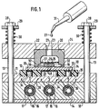
- FIG. 1 shows a flat base plate 18 which has two guide rods 13 aligned approximately parallel to one another and vertically to the base plate 18. Furthermore, a flat base plate 14 is provided, which has two holes through which the guide rods 13 of the base plate 18 protrude. The base plate 14 lies flush with its underside on the top of the base plate 18. Furthermore, a flat intermediate plate 11 is provided, which also has two holes through which the guide rods 13 protrude. The underside of the intermediate plate 11 lies on the upper side of the base plate 14. The base plate 14 has approximately parallel to its flat upper side a plurality of cylindrical recesses 15 lying next to one another, a sleeve 16 with a wire helix 17 being arranged in each cylindrical recess 15.
- the intermediate plate 11 has in the area between the two guide rods 13 on its upper side an approximately circular recess 35, into which an approximately circular disk-shaped, flat carrier plate 12 can be inserted.
- the carrier plate 12 lies approximately in the recess 35, with a plurality of blind holes 34 arranged in the carrier plate 12 pointing with their opening downward toward the intermediate plate 11.
- a plurality of permanent magnets 33 are located in the blind holes 34.
- An electro-optical component 26 is supported on the cuboid elevations 48, the outer flanks of which bear against the ridge-shaped elevations 19. On the surface of its rear side facing away from the elevations 19, 48, this points electro-optical component 26 a ferromagnetic disc 25. Also provided is a trough-shaped container 20 which is open on one side and whose open side points downward toward the stamp 10. The trough-shaped container 20 lies with its border formed by the end face of its side walls on the die 10 and is partially filled with a reaction casting compound 27 in its interior above the surface of the die 10. The reaction casting compound 27 encloses the electro-optical component 26. The trough-shaped container 20 is partly held in a mounting recess 22 in a flat cover plate 24.
- the trough-shaped container 20 has a recess 21 in its top floor which is aligned with a filling opening 23 which is arranged in the cover plate 24.
- the cover plate 24 is likewise guided over the guide rods 13 by means of two bores through which the guide rods 13 protrude and is pressed downwards by means of two spiral springs 30 which are arranged around the guide rods 13. Upward, the coil springs 30 are supported on a stop plate 29, which are fastened with a contact screw 28 on the guide rod 13.
- a pipette 31 is also provided, by means of which the reaction casting compound 27 can be filled into the trough-shaped container 20 through the filling opening 23 and the recess 21.
- the trough-shaped container 20 also has an auxiliary structure 32 in the form of a heel running all around the side walls near the border in its interior.
- the trough-shaped container 20 is first inserted into the cover plate 24, so that its bottom comes to rest in the mounting recess 22.
- the mounting recess 22 is preferably designed such that the trough-shaped container 20 is easily clamped.
- the trough-shaped container 20 is preferably made of a plastic, such as polycarbonate, which, however does not necessarily have to be optically transparent.
- the arrangement described is first completed to the extent that the base plate 18, the base plate 14 and the intermediate plate 11 lie one above the other.
- the carrier plate 12 with the permanent magnets 33 inserted into the blind holes 34 is inserted into the recess 35 of the intermediate plate 11.
- the stamp 10 is then placed on the carrier plate 12.
- the shape of the stamp 10 is fixed in position by the permanent magnets 33.
- the die 10 is aligned so that it occupies a defined position with respect to the trough-shaped container 20 to be placed later.
- the electro-optical component 26 with the ferromagnetic disk 25 located on its rear side is inserted into the die 10, the ridge-shaped elevations 19 and the cuboid elevations 48 effecting an automatic passive adjustment of the electro-optical component 26 with respect to the die 10.
- the cover plate 24 with the inserted trough-shaped container 20 with the opening of the trough-shaped container 20 is pushed down onto the arrangement, the guide rods 13 taking over the mechanical guidance of the cover plate 24.
- the cover plate 24 with the trough-shaped container 20 is pressed onto the surface of the die 10.
- the liquid reaction casting compound 27 is then poured into the interior of the trough-shaped container 20 through the filling opening 23 and the recess 21 by means of the pipette 31.
- the ferromagnetic pressure plate 25 causes the electro-optical component 26 to be pressed against the surface of the die 10 due to the magnetic forces of the magnets 33.
- the reaction casting compound 27 preferably has a low viscosity. It is not necessary to completely fill the trough-shaped container 20 with the reaction casting compound 27.
- the liquid reaction casting compound 27 consists of a polymerizable monomer which is mixed with thermal initiators. The thermal initiators now begin to polymerize the reaction casting compound 27 as the temperature rises above a certain threshold temperature. Since the heat radiation 36 is conducted from below to the die 10, the polymerization begins first on the surface of the reaction die 27 closest to the surface of the die 10.
- the reaction casting compound 27 is preferably composed in such a way that thermal initiators with at least two different temperature thresholds are contained therein. Then heating the arrangement up to the first temperature threshold is sufficient to effect at least partial polymerization of the reaction casting compound 27. The residual monomer remaining in the process can then be removed by heating to the second threshold temperature in a separate heating oven, regardless of the arrangement shown here.
- an optically transparent reaction casting compound 27 should be selected, at least in the area around the optical wavelengths to be used, so that low-loss guidance of the optical signals can be achieved.
- permanent magnets are also provided on or in the electro-optical component 26 in order to prevent the electro-optical component 26 from floating in the liquid reaction casting compound 27.
- the location for the pressure plate 25 or corresponding permanent magnets is variable and preferably on the underside of the electro-optical component 26, which is close to the die 10, since a high contact pressure then develops due to the small distance of the electro-optical component 26 from the die 10 in the integrated optical application area.
- the arrangement is removed from the mold by removing the cover component formed from the trough-shaped container 20 with the solidified reaction casting compound 27 and the electro-optical component 26 embedded therein from the die 10 and from the mounting recess 22.
- mechanical components can also be provided that perform this function.
- any equivalent pressure generation can be used for pressing the trough-shaped container 20 against the die 10.
- the heating can also be done in any other way (combustion, induction, etc.).
- Other guiding or positioning devices or methods can also take the place of the guide rods 13.
- FIG. 2 shows a further exemplary embodiment for an arrangement for producing the cover component.
- the same parts were given the same numbers.
- the arrangement in FIG. 2 differs from the arrangement shown in FIG. 1 in the following points:
- the trough-shaped container 20 has no recess 21, but is a container closed at the bottom.
- the reaction casting compound 27 adheres to the bottom of the trough-shaped container 20 in the form of a cooled gel.
- the elevations 19, 48 on the form stamp 10 in this exemplary embodiment are arranged in a depression in the form stamp 10, the ridge lines of the ridge-shaped elevations 19 with the longitudinal symmetry axes of the cuboid Surveys 48 are aligned.
- the form stamp 10 is also fixed here in its position by means of adjusting bumps 45 on the intermediate plate 11.
- the intermediate plate 11 is solid here and not made with magnets in blind holes.
- the base plate 14 here does not have the heating arrangements comprising a cylindrical recess, sleeve and wire helix, as shown in FIG. 1, but is arranged above a heating plate 46 in which many individual heating wires 47 are arranged next to one another.
- the reaction casting compound 27 was poured into the trough-shaped container 20 in a previous step, the bottom of which was still at the bottom. Then cooling took place, so that the viscosity of the reaction casting compound 27 increased. As a result, the reaction casting compound 27 took the form of a gel which adheres to the bottom of the trough-shaped container 20.
- the arrangement of trough-shaped container 20 and reaction casting compound 27 cooled in this way is now inserted into the arrangement, as described for FIG. 1.
- the reaction casting compound 27 liquefies and follows the force of gravity, so that subsequently the liquefied reaction casting compound 27 on the surface of the die 10 within the interior of the trough-shaped Container 20 comes to rest. This is followed by heating again by the heat radiation 36, which is generated here by the heating wires 47 through which current flows.
- the integrated optical cover component is then again removed from the trough-shaped container 20 with the hardened reaction casting compound 27.
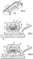
- Figure 3 shows a perspective view of a trough-shaped container 20. In its interior, this has two additional support elements 50.
- the one support element 50 is in the form of a column, which is applied to the bottom of the trough-shaped container 20.
- the other support element 50 has the shape of an additional wall running approximately perpendicular to a side wall.
- the support elements are immersed in the liquid reaction casting compound 27 during the manufacturing process for the integrated optical cover component.
- the liquid reaction casting compound 27 usually dissolves the material of the trough-shaped container 20 and the supporting elements 50 somewhat and then combines with it during thermal curing. As a result, the support elements 50 can later absorb mechanical forces which could otherwise damage the solidified reaction casting compound 27.
- FIG. 4 shows how the trough-shaped container 20 forms a lid component 49 together with the hardened reaction casting compound 27.
- the elevations 19, 48 leave corresponding depressions 42, 43 in the lid component 49.
- a filling compound 51 was introduced into the trough-shaped container.
- the cover component 49 is now placed on a base part 39, which has two roof ridge-shaped adjustment elements 40 on its upper side, which determine the lateral position of the cover component 49.
- a polymer adhesive 44 is introduced between cover component 49 and base part 39 by means of an application tool 37.
- part of the polymer adhesive acts as a connecting material, and another part of the polymer adhesive 44 is forced into the depressions 42, 43.
- the parallelepiped depressions 43 serve here as a waveguide trench, a waveguide being formed therein by filling with the polymer adhesive 44.
- the filling compound 51 does not have to be of high optical quality, but serves primarily for mechanical stability. As a result, the optically effective layer thickness of the solidified reaction casting compound 27 can be kept very thin, which enables inexpensive production.
- FIG. 5 shows an arrangement similar to that shown in FIG. 4, in which the cover component 49 is, however, placed on a substrate 38 which has a waveguide trench 41.
- the cover component 49 only has the cast-in electro-optical component 26 and the ridge-shaped depressions 42 and no cuboid depressions.
- a permanent magnet 52 is applied to the electro-optical component 26, which serves to press the electro-optical component 26 against the die 10.
- the permanent magnet 52 is preferably mounted on the underside of the electro-optical component 26 in order to maximize the effective magnetic attraction.
- the polymer adhesive 44 is applied to the substrate 38 and flows, among other things, into the waveguide trench 41.
- the cover component 49 is held in place by the adjusting elements 40 Position adjusted with respect to the waveguide trench 41 filled with polymer adhesive 44.
- the polymer adhesive 44 also functions here simultaneously as an adhesive for connecting the cover component 49 to the substrate 38, and also for forming a waveguide in the waveguide trench 41, which is optically coupled to the electro-optical component 26.
Landscapes
- Engineering & Computer Science (AREA)
- Mechanical Engineering (AREA)
- Chemical & Material Sciences (AREA)
- Composite Materials (AREA)
- Health & Medical Sciences (AREA)
- Manufacturing & Machinery (AREA)
- Ophthalmology & Optometry (AREA)
- Optical Integrated Circuits (AREA)
- Casting Or Compression Moulding Of Plastics Or The Like (AREA)
Applications Claiming Priority (2)
| Application Number | Priority Date | Filing Date | Title |
|---|---|---|---|
| DE4434832 | 1994-09-29 | ||
| DE4434832A DE4434832A1 (de) | 1994-09-29 | 1994-09-29 | Verfahren zur Herstellung eines integriert optischen Deckelbauteils, integriert optisches Deckelbauteil, Verfahren zur Herstellung eines integriert optischen Bauteils mit einem integriert optischen Deckelbauteil und integriert optisches Bauteil mit einem integriert optischen Deckelbauteil |
Publications (3)
| Publication Number | Publication Date |
|---|---|
| EP0744276A2 true EP0744276A2 (fr) | 1996-11-27 |
| EP0744276A3 EP0744276A3 (fr) | 1997-09-10 |
| EP0744276B1 EP0744276B1 (fr) | 1999-11-17 |
Family
ID=6529525
Family Applications (1)
| Application Number | Title | Priority Date | Filing Date |
|---|---|---|---|
| EP95113948A Expired - Lifetime EP0744276B1 (fr) | 1994-09-29 | 1995-09-06 | Procédé pour la fabrication d'un couvercle en optique intégré, couvercle en optique intégré, procédé pour la fabrication d'un élément en optique intégré avec un couvercle en optique intégré et élément en optique intégré avec un couvercle en optique intégré |
Country Status (2)
| Country | Link |
|---|---|
| EP (1) | EP0744276B1 (fr) |
| DE (2) | DE4434832A1 (fr) |
Cited By (2)
| Publication number | Priority date | Publication date | Assignee | Title |
|---|---|---|---|---|
| EP0743152A3 (fr) * | 1995-05-15 | 1997-09-10 | Bosch Gmbh Robert | Cadre de moulage, procédé pour la fabrication d'un produit à micropores, produit à micropores, procédé pour la fabrication d'un élément optique intégré et élément optique intégré |
| GB2310821A (en) * | 1996-03-06 | 1997-09-10 | Bosch Gmbh Robert | Separating a casting from a mould cavity |
Families Citing this family (1)
| Publication number | Priority date | Publication date | Assignee | Title |
|---|---|---|---|---|
| DE19642088A1 (de) * | 1996-10-12 | 1998-04-16 | Bosch Gmbh Robert | Verfahren zur Herstellung eines mikrostrukturierten Körpers, eines Gußrahmens und eines integriert-optischen Bauteils |
Citations (1)
| Publication number | Priority date | Publication date | Assignee | Title |
|---|---|---|---|---|
| WO1994008236A1 (fr) | 1992-10-07 | 1994-04-14 | Ecossensors Limited | Membranes permeables aux gaz pour des electrodes a gaz amperometriques, et leurs utilisations |
Family Cites Families (4)
| Publication number | Priority date | Publication date | Assignee | Title |
|---|---|---|---|---|
| US2701894A (en) * | 1950-09-09 | 1955-02-15 | Gen Electric | Method and apparatus for forming panel units |
| US3272904A (en) * | 1961-01-03 | 1966-09-13 | Automotive Rubber Company Inc | Method of making sealing members |
| US3838316A (en) * | 1973-10-09 | 1974-09-24 | Western Electric Co | Encapsulated electrical component assembly and method of fabrication |
| US4335932A (en) * | 1980-02-29 | 1982-06-22 | Amp Incorporated | Elastomeric potting shell |
-
1994
- 1994-09-29 DE DE4434832A patent/DE4434832A1/de not_active Withdrawn
-
1995
- 1995-09-06 EP EP95113948A patent/EP0744276B1/fr not_active Expired - Lifetime
- 1995-09-06 DE DE59507249T patent/DE59507249D1/de not_active Expired - Fee Related
Patent Citations (1)
| Publication number | Priority date | Publication date | Assignee | Title |
|---|---|---|---|---|
| WO1994008236A1 (fr) | 1992-10-07 | 1994-04-14 | Ecossensors Limited | Membranes permeables aux gaz pour des electrodes a gaz amperometriques, et leurs utilisations |
Cited By (4)
| Publication number | Priority date | Publication date | Assignee | Title |
|---|---|---|---|---|
| EP0743152A3 (fr) * | 1995-05-15 | 1997-09-10 | Bosch Gmbh Robert | Cadre de moulage, procédé pour la fabrication d'un produit à micropores, produit à micropores, procédé pour la fabrication d'un élément optique intégré et élément optique intégré |
| GB2310821A (en) * | 1996-03-06 | 1997-09-10 | Bosch Gmbh Robert | Separating a casting from a mould cavity |
| GB2310821B (en) * | 1996-03-06 | 1998-11-04 | Bosch Gmbh Robert | A device for taking a casting from a microstructured substrate |
| US5935622A (en) * | 1996-03-06 | 1999-08-10 | Harting Elecktro-Optische Bauteile Gmbh & Co Kg | Device for shaping a microstructure substrate |
Also Published As
| Publication number | Publication date |
|---|---|
| DE4434832A1 (de) | 1996-04-04 |
| EP0744276B1 (fr) | 1999-11-17 |
| DE59507249D1 (de) | 1999-12-23 |
| EP0744276A3 (fr) | 1997-09-10 |
Similar Documents
| Publication | Publication Date | Title |
|---|---|---|
| EP0614539B1 (fr) | Procede de fabrication d'un couvercle pour un circuit optique integre | |
| DE19909242A1 (de) | Verfahren und Gießform zum Herstellen eines elektrooptischen Moduls und elektrooptisches Modul | |
| DE3004437A1 (de) | Verfahren zum herstellen eines magnetdomaenen-bauelements | |
| DE102015119235B4 (de) | Vorrichtung zum Spritzgießen und Umspritzen von Objekten | |
| DE2557701C3 (de) | Verfahren zur Herstellung der Aufnahmeplatte einer Vorrichtung zum paßgenauen Aufspannen von Werkstücken | |
| EP0744276B1 (fr) | Procédé pour la fabrication d'un couvercle en optique intégré, couvercle en optique intégré, procédé pour la fabrication d'un élément en optique intégré avec un couvercle en optique intégré et élément en optique intégré avec un couvercle en optique intégré | |
| DE4240950C1 (de) | Verfahren zum Herstellen eines Deckels für eine integriert optische Schaltung und Deckel für eine integriert optische Schaltung | |
| DE4329546C2 (de) | Flachheizkörper | |
| EP0850750A2 (fr) | Procédé pour la fabrication d'un produit à micropores, un cadre de moulage et un élément optique intégré | |
| EP0731365B1 (fr) | Méthode de fabrication d'un dispositif électro-optique | |
| WO2003003538A2 (fr) | Piece secondaire scellee pour moteurs electriques | |
| DE4438053C2 (de) | Verfahren zum Herstellen einer elektrisch leitfähigen Struktur | |
| EP0743152A2 (fr) | Cadre de moulage, procédé pour la fabrication d'un produit à micropores, produit à micropores, procédé pour la fabrication d'un élément optique intégré et élément optique intégré | |
| DE19608667C2 (de) | Einrichtung zur Abformung eines Mikrostruktursubstrates | |
| EP0533072A1 (fr) | Elément de chauffage plat | |
| DE69032335T2 (de) | Verfahren zur Einkapselung einer integrierten Schaltung auf einem Träger, Anordnung zur Benutzung dieses Verfahrens und eine nach diesem Verfahren hergestellte elektronische Anordnung | |
| DE102005020689B3 (de) | Verfahren zur Herstellung einer Isolierplatte | |
| EP1005663B1 (fr) | Procede de production d'un composant optique integre a la puce a guides d'ondes avec connecteur enfichable | |
| DE4200396C1 (fr) | ||
| DE3343028C2 (de) | Vorrichtung für die Herstellung eines Tintendruckkopfes | |
| DE3216192A1 (de) | Elektrisches bauelement, das zentriert und justiert in einem gehaeuse untergebracht ist | |
| DE19721721B4 (de) | Verfahren zur Herstellung thermooptischer Schaltelemente | |
| DE69917174T2 (de) | Spritzgegossene Heizungsplatte, Zusammensetzung, Vorrichtung und Verfahren zu deren Herstellung | |
| WO1997001120A1 (fr) | Procede et dispositif de montage utile pour former un connecteur multibroches pour guides d'ondes lumineuses | |
| DE60004344T2 (de) | Herstellung eines silikonteiles zum aufkleben |
Legal Events
| Date | Code | Title | Description |
|---|---|---|---|
| PUAI | Public reference made under article 153(3) epc to a published international application that has entered the european phase |
Free format text: ORIGINAL CODE: 0009012 |
|
| AK | Designated contracting states |
Kind code of ref document: A2 Designated state(s): DE FR NL |
|
| PUAL | Search report despatched |
Free format text: ORIGINAL CODE: 0009013 |
|
| AK | Designated contracting states |
Kind code of ref document: A3 Designated state(s): DE FR NL |
|
| 17P | Request for examination filed |
Effective date: 19980310 |
|
| 17Q | First examination report despatched |
Effective date: 19980701 |
|
| RAP1 | Party data changed (applicant data changed or rights of an application transferred) |
Owner name: HARTING ELEKTRO-OPTISCHE BAUTEILE GMBH & CO. KG. |
|
| GRAG | Despatch of communication of intention to grant |
Free format text: ORIGINAL CODE: EPIDOS AGRA |
|
| GRAG | Despatch of communication of intention to grant |
Free format text: ORIGINAL CODE: EPIDOS AGRA |
|
| GRAH | Despatch of communication of intention to grant a patent |
Free format text: ORIGINAL CODE: EPIDOS IGRA |
|
| GRAH | Despatch of communication of intention to grant a patent |
Free format text: ORIGINAL CODE: EPIDOS IGRA |
|
| GRAH | Despatch of communication of intention to grant a patent |
Free format text: ORIGINAL CODE: EPIDOS IGRA |
|
| GRAA | (expected) grant |
Free format text: ORIGINAL CODE: 0009210 |
|
| AK | Designated contracting states |
Kind code of ref document: B1 Designated state(s): DE FR NL |
|
| PG25 | Lapsed in a contracting state [announced via postgrant information from national office to epo] |
Ref country code: NL Free format text: LAPSE BECAUSE OF FAILURE TO SUBMIT A TRANSLATION OF THE DESCRIPTION OR TO PAY THE FEE WITHIN THE PRESCRIBED TIME-LIMIT Effective date: 19991117 Ref country code: FR Free format text: LAPSE BECAUSE OF FAILURE TO SUBMIT A TRANSLATION OF THE DESCRIPTION OR TO PAY THE FEE WITHIN THE PRESCRIBED TIME-LIMIT Effective date: 19991117 |
|
| REF | Corresponds to: |
Ref document number: 59507249 Country of ref document: DE Date of ref document: 19991223 |
|
| NLV1 | Nl: lapsed or annulled due to failure to fulfill the requirements of art. 29p and 29m of the patents act | ||
| EN | Fr: translation not filed | ||
| PLBE | No opposition filed within time limit |
Free format text: ORIGINAL CODE: 0009261 |
|
| STAA | Information on the status of an ep patent application or granted ep patent |
Free format text: STATUS: NO OPPOSITION FILED WITHIN TIME LIMIT |
|
| 26N | No opposition filed | ||
| PGFP | Annual fee paid to national office [announced via postgrant information from national office to epo] |
Ref country code: DE Payment date: 20041001 Year of fee payment: 10 |
|
| PG25 | Lapsed in a contracting state [announced via postgrant information from national office to epo] |
Ref country code: DE Free format text: LAPSE BECAUSE OF NON-PAYMENT OF DUE FEES Effective date: 20060401 |