EP0744526A1 - Méthode pour contrÔler la direction d'un outil de forage - Google Patents
Méthode pour contrÔler la direction d'un outil de forage Download PDFInfo
- Publication number
- EP0744526A1 EP0744526A1 EP95107954A EP95107954A EP0744526A1 EP 0744526 A1 EP0744526 A1 EP 0744526A1 EP 95107954 A EP95107954 A EP 95107954A EP 95107954 A EP95107954 A EP 95107954A EP 0744526 A1 EP0744526 A1 EP 0744526A1
- Authority
- EP
- European Patent Office
- Prior art keywords
- tool
- drilling
- control loop
- actuators
- internal control
- Prior art date
- Legal status (The legal status is an assumption and is not a legal conclusion. Google has not performed a legal analysis and makes no representation as to the accuracy of the status listed.)
- Granted
Links
- 238000005553 drilling Methods 0.000 title claims abstract description 56
- 238000000034 method Methods 0.000 title claims description 18
- 230000015572 biosynthetic process Effects 0.000 claims abstract description 5
- 238000005755 formation reaction Methods 0.000 claims abstract description 5
- 238000012545 processing Methods 0.000 claims abstract description 4
- 230000009471 action Effects 0.000 claims abstract description 3
- 230000001133 acceleration Effects 0.000 claims description 4
- 230000005484 gravity Effects 0.000 claims description 4
- 230000008569 process Effects 0.000 description 4
- 230000005540 biological transmission Effects 0.000 description 3
- 239000003795 chemical substances by application Substances 0.000 description 3
- 238000012937 correction Methods 0.000 description 3
- 238000011010 flushing procedure Methods 0.000 description 3
- 238000011156 evaluation Methods 0.000 description 2
- 238000005259 measurement Methods 0.000 description 2
- 238000011022 operating instruction Methods 0.000 description 2
- 239000003381 stabilizer Substances 0.000 description 2
- 230000008859 change Effects 0.000 description 1
- 238000010276 construction Methods 0.000 description 1
- 230000006870 function Effects 0.000 description 1
- 230000001788 irregular Effects 0.000 description 1
- 238000012544 monitoring process Methods 0.000 description 1
- 230000000750 progressive effect Effects 0.000 description 1
- 239000011435 rock Substances 0.000 description 1
Images



Classifications
-
- E—FIXED CONSTRUCTIONS
- E21—EARTH OR ROCK DRILLING; MINING
- E21B—EARTH OR ROCK DRILLING; OBTAINING OIL, GAS, WATER, SOLUBLE OR MELTABLE MATERIALS OR A SLURRY OF MINERALS FROM WELLS
- E21B44/00—Automatic control systems specially adapted for drilling operations, i.e. self-operating systems which function to carry out or modify a drilling operation without intervention of a human operator, e.g. computer-controlled drilling systems; Systems specially adapted for monitoring a plurality of drilling variables or conditions
- E21B44/005—Below-ground automatic control systems
-
- E—FIXED CONSTRUCTIONS
- E21—EARTH OR ROCK DRILLING; MINING
- E21B—EARTH OR ROCK DRILLING; OBTAINING OIL, GAS, WATER, SOLUBLE OR MELTABLE MATERIALS OR A SLURRY OF MINERALS FROM WELLS
- E21B44/00—Automatic control systems specially adapted for drilling operations, i.e. self-operating systems which function to carry out or modify a drilling operation without intervention of a human operator, e.g. computer-controlled drilling systems; Systems specially adapted for monitoring a plurality of drilling variables or conditions
-
- E—FIXED CONSTRUCTIONS
- E21—EARTH OR ROCK DRILLING; MINING
- E21B—EARTH OR ROCK DRILLING; OBTAINING OIL, GAS, WATER, SOLUBLE OR MELTABLE MATERIALS OR A SLURRY OF MINERALS FROM WELLS
- E21B47/00—Survey of boreholes or wells
- E21B47/02—Determining slope or direction
- E21B47/022—Determining slope or direction of the borehole, e.g. using geomagnetism
-
- E—FIXED CONSTRUCTIONS
- E21—EARTH OR ROCK DRILLING; MINING
- E21B—EARTH OR ROCK DRILLING; OBTAINING OIL, GAS, WATER, SOLUBLE OR MELTABLE MATERIALS OR A SLURRY OF MINERALS FROM WELLS
- E21B7/00—Special methods or apparatus for drilling
- E21B7/04—Directional drilling
- E21B7/06—Deflecting the direction of boreholes
- E21B7/062—Deflecting the direction of boreholes the tool shaft rotating inside a non-rotating guide travelling with the shaft
Definitions
- the invention relates to a method for controlling a drilling tool, which can be directed at least by a group of controllable actuators assigned to the tool and distributed over the tool circumference, during drilling operation in underground formations according to the preamble of claim 1.
- the setpoint values for the course of the drilling tool between a starting point and a target point are given to the in-tool control loop, which are compared by the in-tool control loop with actual course values, which are determined by the in-tool measurement sensor for the direction of the drilling tool and its depth.
- the tool-internal control circuit calculates correction data for the drilling direction that are suitable for tracing the drilling tool back to its target course.
- the tool-internal control loop is in data exchange with an external control loop, which evaluates the data received from underground and makes it possible to provide operating instructions or new data to the tool-internal control loop, for example for a changed course or the tool depth measured during the day. Until new operating instructions are received or Course data and then the internal control loop determines the course of the drilling tool until the target is reached.
- the invention is concerned with the problem of creating a method of the type mentioned which enables precise surface tool guidance.
- the invention solves the problem by means of a method having the features of claim 1. With regard to further essential configurations, reference is made to claims 2 to 4.
- the method according to the invention assigns the external control loop the main control function which the latter can automatically perform after evaluating the data received during the day.
- the external control loop assigns the external control function which the latter can automatically perform after evaluating the data received during the day.
- there is the possibility of individual influence on the tool course by an operator following the action underground who, like with automatic course specification, can carry out the tool control solely by specifying a single control vector.
- This enables extremely cautious, quickly correctable course determinations, which enables drilling a borehole with a smooth curve that is largely free of kinks and jags.
- This is particularly important in the case of bores with a far-reaching horizontal course, the range of which is decisively influenced by the drill string friction in the borehole, because the more irregular the course of the borehole, the greater it is.
- the method according to the invention therefore favors the creation of horizontal bores with an extended range.
- Fig. 1 illustrates schematically a drilling rig 1 for sinking boreholes 2 into underground rock formations with the aid of a drilling tool 3 at the front end of a drill string 4, the progressive construction and drive of which is generally known and requires no further explanation.
- a non-rotating drilling string can also be used with a drilling tool, the drill bit of which is driven by an underground motor.
- the above-ground operation center is shown directly adjacent to the drilling rig 1 in the example shown and is designated by 5, but can also be set up at any distance from the drilling rig 1, provided that a suitable transmission of drilling operating data is ensured, which in the example shown is carried out by an electrical device Line connection 6 is made.
- the tool 3 comprises a housing 8 screwed to the drill string 4 at 7, which is screwed at 9 with a retracted extension 10, which is connected at its lower end via a screw connection 11 to a drill bit 12.
- the housing 8 and its extension 9 have a central flow channel 13 for the passage of a flushing agent which flows down the drill string 4, exits the drill bit 12 into the borehole 2 and in the annular space between the wall of the borehole 2 and the tool 3 or the drill string 4 flows back to the drilling system 1, where it reaches a mud tank, not shown, from which it is conveyed into the drill string 4 by means of a mud pump.
- a generator 16 for the power supply to the electrical consumers on the tool side, which can be driven by a turbine 17, which is only indicated schematically and is acted upon by the flushing agent flow.
- Generator 16 and turbine 17 can form part of an underground information receiver, the receiving and further processing part of which is indicated schematically at 18.
- an information transmitter indicated at 19, for example a pulse transmitter acting on the flushing agent flow, with the aid of which tool-internal data present during the day can be transmitted to an above-ground information receiver, which is only schematically illustrated at 20.
- the above-ground information provider for above-ground data to be transmitted to the control system of the drilling tool 3 is also only indicated schematically in FIG. 1 and designated by 21.
- a sleeve-shaped housing part 25 is rotatably supported via bearings 23, which assumes a non-rotating position in the borehole 2 during operation, while the drill string 4, housing 8, extension 10 and drill bit 12 about their central axis as a result of the surface drive of drill string 4 rotate.
- the housing part 25 is provided with three actuators in the form of ribs 26, 27, 28, which have a shape similar to a stabilizer rib and are each supported on the housing part 25 such that they can be folded about an axis 29.
- the ribs 26, 27, 28 can be transferred individually and independently of one another by means of a pressure medium drive 30, 31, 32 from the folded starting position shown in FIG. 4 to a more or less extended operating position, in which they are on the wall of the borehole 2 apply and exert an individually definable pressure force on them.
- a hydraulic pump 33 is provided in the housing part 25, which acts on the pressure medium drives 30, 31, 32 with hydraulic medium via hydraulic lines 34.
- the hydraulic pump 33 can be driven by means of an electric motor which is generated by the generator 16 or is powered by a battery supplied by this.
- actuators instead of three actuators, which are sufficient for precise alignment of the drilling tool 3, more than three, for example four or five, actuators can also be provided.
- an electronic control system is accommodated in the housing part 25, which is indicated at 35 and comprises sensors 36 for recording required measurement values and an evaluation and arithmetic unit 37 which forms part of an internal control loop.
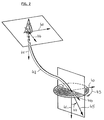
- the measured values required by the method for tool control according to the invention include the current drilling direction 45, which, due to the angle 43 of the tool of the tool axes 58, forms a reference direction, for example the magnetic north direction 40 (FIG. 2) (azimuth) and the Angle 44 of tool axis 58 to a further reference direction, preferably the direction of gravitational acceleration 41, can be defined.
- These measured values are determined by sensors 36 on the tool side.
- the required measured values also include the rotational angle position of the drilling tool 3 in the borehole 2 with respect to a reference plane, preferably a plane 53 which intersects the zero point 50 of a plane coordinate system 51 which is permanently assigned to the drilling tool 3 and coincides with the direction of the acceleration due to gravity and which is the top of the tool 3 intersects in an upper culmination line defined by the culmination points 52.
- the current angle of rotation position of the drilling tool 3 results as the angle 54 between the reference plane 53 defined by the direction of gravity and the reference plane 55 fixed to the tool, which coincides with the ordinate of the coordinate system fixed to the tool. so that complete information about the alignment and orientation of the drilling tool 3 is given.
- the force with which the ribs 26, 27, 28 press against the wall of the borehole 2 is also determined. This can be done by means of pressure sensors or derived from the control valve settings for the pressure medium drives 30, 31, 32. A resulting force is determined from the individual forces, which force is defined according to magnitude and direction and forms a control vector 56.
- the direction of the control vector 56 intersecting the zero point of the fixed coordinate system 51 and the tool axis 58 is defined as the angle 57, which the control vector 56 forms with the reference plane 53.
- the sensors 36 belonging to the tool-internal control circuit 60 provide the measured values for the current drilling direction of the drilling tool 3, the current setting of the actuators 26, 27, 28 and the rotation angle orientation (Angle 54) of the drilling tool 3 determined.
- This data is transferred to a computing part 61 of the tool-internal control circuit 60, which compensates for deviations of the reference plane 55 fixed to the tool from the reference plane 53 specified in the direction of acceleration due to gravity, and determines the direction (angle 57) and amount of the current control vector 56.
- the entire and processed data are transferred via a data transmission system 62, which includes, for example, the information provider 19 and the information receiver 21, to an external control circuit 70, in which this data is processed in a manner to be described.
- a data transmission system 62 which includes, for example, the information provider 19 and the information receiver 21, to an external control circuit 70, in which this data is processed in a manner to be described.
- the compensated actual control vector values supplied by the arithmetic element 61 become one in the tool-internal control loop
- Comparison part 63 of the control circuit 60 is compared with predetermined, stored control vector target values and the result value is fed to the evaluation and arithmetic unit 37 of the tool-internal control system 35, which, if necessary, corrects the setting of the actuators 26, 27, 28.
- the actual values of the current drilling direction of the drilling tool 3 delivered by the tool-internal control circuit 60 are compared with directional setpoints stored above ground in a computer 72, and the current geological position of the drilling tool 3 is determined, taking into account the tool depth determined above ground by a measuring device 71. If there are deviations from the specified course that make a correction necessary, suitable new setpoints for the control vector 56 can be automatically determined and via a control unit 73 in which the data e.g. are encoded as a digital sequence of signals and are transferred to the tool-internal control circuit 60 via a data transmission system 74.
- the data transmitted from the computer 72 to a monitoring unit 75 can give an operator cause to implement a control vector 56 that he has selected, which can be done by a corresponding input at 76.
- a personal control system can be used to predefine a course for the drilling tool 3 which moves outside the possibilities specified in the program. This can be useful not only for the purpose of optimizing a course correction, but also if a course change is indicated on the basis of other data found during the day, for example about the type of pierced formations.
- the external control circuit 70 can switch to the tool-internal control circuit 60
- Direction hold command are transmitted, in which case the current actual direction values of the drilling tool 3 are stored in a data memory of the tool-internal control circuit 60, which can be assigned to the comparison part 63, as a setpoint value and then continuously compared with further determined actual direction values.
- Control variables based on such a direction actual value / setpoint value comparison are now generated for the setting of the actuators 26, 27, 28, instead of control variables which are derived from a predetermined control vector.
- the tool-internal control circuit 60 then switches back to the operating mode described above.
Landscapes
- Life Sciences & Earth Sciences (AREA)
- Engineering & Computer Science (AREA)
- Geology (AREA)
- Mining & Mineral Resources (AREA)
- Physics & Mathematics (AREA)
- Environmental & Geological Engineering (AREA)
- Fluid Mechanics (AREA)
- General Life Sciences & Earth Sciences (AREA)
- Geochemistry & Mineralogy (AREA)
- Geophysics (AREA)
- Earth Drilling (AREA)
Priority Applications (3)
| Application Number | Priority Date | Filing Date | Title |
|---|---|---|---|
| EP19950107954 EP0744526B1 (fr) | 1995-05-24 | 1995-05-24 | Méthode pour contrôler la direction d'un outil de forage |
| DE59509490T DE59509490D1 (de) | 1995-05-24 | 1995-05-24 | Verfahren zum Steuern eines Bohrwerkzeugs |
| NO962113A NO962113L (no) | 1995-05-24 | 1996-05-23 | Fremgangsmåte til styring av et boreverktöy under boring i underjordiske formasjoner |
Applications Claiming Priority (1)
| Application Number | Priority Date | Filing Date | Title |
|---|---|---|---|
| EP19950107954 EP0744526B1 (fr) | 1995-05-24 | 1995-05-24 | Méthode pour contrôler la direction d'un outil de forage |
Publications (2)
| Publication Number | Publication Date |
|---|---|
| EP0744526A1 true EP0744526A1 (fr) | 1996-11-27 |
| EP0744526B1 EP0744526B1 (fr) | 2001-08-08 |
Family
ID=8219289
Family Applications (1)
| Application Number | Title | Priority Date | Filing Date |
|---|---|---|---|
| EP19950107954 Expired - Lifetime EP0744526B1 (fr) | 1995-05-24 | 1995-05-24 | Méthode pour contrôler la direction d'un outil de forage |
Country Status (3)
| Country | Link |
|---|---|
| EP (1) | EP0744526B1 (fr) |
| DE (1) | DE59509490D1 (fr) |
| NO (1) | NO962113L (fr) |
Cited By (15)
| Publication number | Priority date | Publication date | Assignee | Title |
|---|---|---|---|---|
| US6092610A (en) * | 1998-02-05 | 2000-07-25 | Schlumberger Technology Corporation | Actively controlled rotary steerable system and method for drilling wells |
| US6109372A (en) * | 1999-03-15 | 2000-08-29 | Schlumberger Technology Corporation | Rotary steerable well drilling system utilizing hydraulic servo-loop |
| US6158529A (en) * | 1998-12-11 | 2000-12-12 | Schlumberger Technology Corporation | Rotary steerable well drilling system utilizing sliding sleeve |
| GB2391349A (en) * | 2001-12-20 | 2004-02-04 | Schlumberger Holdings | Manipulating Multiple Sections of a Well Bore Design Trajectory |
| WO2004097160A2 (fr) | 2003-04-25 | 2004-11-11 | Intersyn Technologies | Systemes et procedes utilisant une transmission variable de façon continue afin de commander un ou plusieurs composants de systeme |
| GB2402954A (en) * | 2003-06-18 | 2004-12-22 | Weatherford Lamb | Tool actuator with automatic control |
| WO2004113666A1 (fr) * | 2003-06-17 | 2004-12-29 | Noble Drilling Services Inc. | Enveloppe ouvrante pour outil orientable rotatif |
| US7136795B2 (en) | 1999-11-10 | 2006-11-14 | Schlumberger Technology Corporation | Control method for use with a steerable drilling system |
| US7168507B2 (en) | 2002-05-13 | 2007-01-30 | Schlumberger Technology Corporation | Recalibration of downhole sensors |
| US7188685B2 (en) | 2001-12-19 | 2007-03-13 | Schlumberge Technology Corporation | Hybrid rotary steerable system |
| US7267184B2 (en) | 2003-06-17 | 2007-09-11 | Noble Drilling Services Inc. | Modular housing for a rotary steerable tool |
| WO2008145950A1 (fr) * | 2007-05-30 | 2008-12-04 | Sondex Limited | Capteur d'orientation pour outil de forage |
| CN102995690A (zh) * | 2012-08-21 | 2013-03-27 | 福州市第三建筑工程公司 | 桩孔垂直度与断面校正机构及其施工方法 |
| US10280693B2 (en) | 2016-12-14 | 2019-05-07 | Helmerich & Payne, Inc. | Mobile utility articulating boom system |
| US12428948B2 (en) | 2018-09-21 | 2025-09-30 | Halliburton Energy Services, Inc. | Wellbore trajectory model calibration for directional drilling |
Families Citing this family (3)
| Publication number | Priority date | Publication date | Assignee | Title |
|---|---|---|---|---|
| DE60011587T2 (de) | 1999-11-10 | 2005-06-30 | Schlumberger Holdings Ltd., Road Town | Steuerungsverfahren für steuerbares bohrsystem |
| EP1402145B2 (fr) † | 2002-05-15 | 2010-03-17 | Baker Hughes Incorporated | Ensemble de forage en boucle fermee avec equipement electronique place a l'exterieur d'une gaine non rotative |
| US7556105B2 (en) * | 2002-05-15 | 2009-07-07 | Baker Hughes Incorporated | Closed loop drilling assembly with electronics outside a non-rotating sleeve |
Citations (1)
| Publication number | Priority date | Publication date | Assignee | Title |
|---|---|---|---|---|
| US5341886A (en) * | 1989-12-22 | 1994-08-30 | Patton Bob J | System for controlled drilling of boreholes along planned profile |
-
1995
- 1995-05-24 DE DE59509490T patent/DE59509490D1/de not_active Expired - Lifetime
- 1995-05-24 EP EP19950107954 patent/EP0744526B1/fr not_active Expired - Lifetime
-
1996
- 1996-05-23 NO NO962113A patent/NO962113L/no unknown
Patent Citations (1)
| Publication number | Priority date | Publication date | Assignee | Title |
|---|---|---|---|---|
| US5341886A (en) * | 1989-12-22 | 1994-08-30 | Patton Bob J | System for controlled drilling of boreholes along planned profile |
Cited By (26)
| Publication number | Priority date | Publication date | Assignee | Title |
|---|---|---|---|---|
| US6092610A (en) * | 1998-02-05 | 2000-07-25 | Schlumberger Technology Corporation | Actively controlled rotary steerable system and method for drilling wells |
| US6158529A (en) * | 1998-12-11 | 2000-12-12 | Schlumberger Technology Corporation | Rotary steerable well drilling system utilizing sliding sleeve |
| US6109372A (en) * | 1999-03-15 | 2000-08-29 | Schlumberger Technology Corporation | Rotary steerable well drilling system utilizing hydraulic servo-loop |
| US7136795B2 (en) | 1999-11-10 | 2006-11-14 | Schlumberger Technology Corporation | Control method for use with a steerable drilling system |
| US7188685B2 (en) | 2001-12-19 | 2007-03-13 | Schlumberge Technology Corporation | Hybrid rotary steerable system |
| GB2391349A (en) * | 2001-12-20 | 2004-02-04 | Schlumberger Holdings | Manipulating Multiple Sections of a Well Bore Design Trajectory |
| US6757613B2 (en) | 2001-12-20 | 2004-06-29 | Schlumberger Technology Corporation | Graphical method for designing the trajectory of a well bore |
| GB2391349B (en) * | 2001-12-20 | 2006-05-31 | Schlumberger Holdings | Designing the trajectory of a well bore |
| US7168507B2 (en) | 2002-05-13 | 2007-01-30 | Schlumberger Technology Corporation | Recalibration of downhole sensors |
| WO2004097160A2 (fr) | 2003-04-25 | 2004-11-11 | Intersyn Technologies | Systemes et procedes utilisant une transmission variable de façon continue afin de commander un ou plusieurs composants de systeme |
| US7267184B2 (en) | 2003-06-17 | 2007-09-11 | Noble Drilling Services Inc. | Modular housing for a rotary steerable tool |
| WO2004113666A1 (fr) * | 2003-06-17 | 2004-12-29 | Noble Drilling Services Inc. | Enveloppe ouvrante pour outil orientable rotatif |
| US7252152B2 (en) | 2003-06-18 | 2007-08-07 | Weatherford/Lamb, Inc. | Methods and apparatus for actuating a downhole tool |
| GB2402954A (en) * | 2003-06-18 | 2004-12-22 | Weatherford Lamb | Tool actuator with automatic control |
| GB2402954B (en) * | 2003-06-18 | 2007-11-21 | Weatherford Lamb | Methods and apparatus for actuating a downhole tool |
| US7503398B2 (en) | 2003-06-18 | 2009-03-17 | Weatherford/Lamb, Inc. | Methods and apparatus for actuating a downhole tool |
| WO2008145950A1 (fr) * | 2007-05-30 | 2008-12-04 | Sondex Limited | Capteur d'orientation pour outil de forage |
| GB2464840A (en) * | 2007-05-30 | 2010-05-05 | Sondex Ltd | Orientation sensor for downhole tool |
| GB2464840B (en) * | 2007-05-30 | 2012-10-03 | Sondex Ltd | Orientation sensor for downhole tool |
| CN102995690A (zh) * | 2012-08-21 | 2013-03-27 | 福州市第三建筑工程公司 | 桩孔垂直度与断面校正机构及其施工方法 |
| US10280693B2 (en) | 2016-12-14 | 2019-05-07 | Helmerich & Payne, Inc. | Mobile utility articulating boom system |
| US10597948B2 (en) | 2016-12-14 | 2020-03-24 | Helmerich & Payne, Inc. | Mobile boom system |
| US10781644B2 (en) | 2016-12-14 | 2020-09-22 | Helmerich & Payne, Inc. | Mobile boom system |
| US11365591B2 (en) | 2016-12-14 | 2022-06-21 | Helmerich & Payne, Inc. | Mobile boom system |
| US12460484B2 (en) | 2016-12-14 | 2025-11-04 | Helmerich & Payne, Inc. | Mobile boom system |
| US12428948B2 (en) | 2018-09-21 | 2025-09-30 | Halliburton Energy Services, Inc. | Wellbore trajectory model calibration for directional drilling |
Also Published As
| Publication number | Publication date |
|---|---|
| NO962113D0 (no) | 1996-05-23 |
| DE59509490D1 (de) | 2001-09-13 |
| EP0744526B1 (fr) | 2001-08-08 |
| NO962113L (no) | 1996-11-25 |
Similar Documents
| Publication | Publication Date | Title |
|---|---|---|
| EP0744526B1 (fr) | Méthode pour contrôler la direction d'un outil de forage | |
| DE69605779T2 (de) | Von der öberfläche aus kontrolliertes richtbohrwerkzeug | |
| EP3081737B1 (fr) | Appareil de forage destine a pratiquer un forage tube et procede de fonctionnement d'un appareil de forage | |
| DE60011587T2 (de) | Steuerungsverfahren für steuerbares bohrsystem | |
| DE60207559T2 (de) | Richtbohrwerkzeug | |
| DE2211734A1 (de) | Steuerung fuer bohreinrichtungen | |
| DE69509557T2 (de) | Richtbohren mit bohrlochmotor | |
| DE102007003080B4 (de) | Unterirdische Bohrmaschine und Verfahren zum Steuern des unterirdischen Bohrens | |
| EP0246589A1 (fr) | Pieu en béton préfabriqué ainsi que méthode et dispositif pour l'enfoncer dans le sol | |
| DE112017001152T5 (de) | System und verfahren für downlink-kommunikation | |
| EP3299523B1 (fr) | Procédé et dispositif pour le traitement d'un sol de fondation | |
| EP3088151A1 (fr) | Mode marche arrière pour systèmes de carotteuse | |
| DE102020119514A1 (de) | Systeme und verfahren zum verlegen eines unterirdischen faseroptischen kabels | |
| EP1117901B1 (fr) | Procede de commande d'un appareil de forage horizontal | |
| DE102013205827A1 (de) | Vorschubeinrichtung | |
| DE3000239C2 (de) | Einrichtung zur Herstellung zielgerichteter Bohrungen | |
| EP3533932B1 (fr) | Procédé et système permettant d'ériger un élément de fondation dans le sol | |
| AT394090B (de) | Verfahren und anordnung zum bohren eines lochs in einen felsen | |
| DE3902868C1 (fr) | ||
| WO2015086126A2 (fr) | Dispositif et procédé de verrouillage pour porte-outil d'une installation de forage rotatif | |
| EP3536900A1 (fr) | Procédé et engin de forage | |
| EP4063567A1 (fr) | Procédé de construction et agencement permettant de mettre en oevre un projet de construction | |
| EP1220973A1 (fr) | Dispositif de fon age controle de trous de forage | |
| CH653406A5 (de) | Einrichtung zur herstellung zielgerichteter bohrungen. | |
| EP4033032B1 (fr) | Procédés et appareil de génie civil destiné au traitement du sol |
Legal Events
| Date | Code | Title | Description |
|---|---|---|---|
| PUAI | Public reference made under article 153(3) epc to a published international application that has entered the european phase |
Free format text: ORIGINAL CODE: 0009012 |
|
| AK | Designated contracting states |
Kind code of ref document: A1 Designated state(s): DE FR GB NL |
|
| 17P | Request for examination filed |
Effective date: 19970109 |
|
| 17Q | First examination report despatched |
Effective date: 19991021 |
|
| GRAG | Despatch of communication of intention to grant |
Free format text: ORIGINAL CODE: EPIDOS AGRA |
|
| GRAH | Despatch of communication of intention to grant a patent |
Free format text: ORIGINAL CODE: EPIDOS IGRA |
|
| GRAH | Despatch of communication of intention to grant a patent |
Free format text: ORIGINAL CODE: EPIDOS IGRA |
|
| RAP1 | Party data changed (applicant data changed or rights of an application transferred) |
Owner name: ENI S.P.A. Owner name: BAKER HUGHES INCORPORATED |
|
| GRAA | (expected) grant |
Free format text: ORIGINAL CODE: 0009210 |
|
| AK | Designated contracting states |
Kind code of ref document: B1 Designated state(s): DE FR GB NL |
|
| GBT | Gb: translation of ep patent filed (gb section 77(6)(a)/1977) |
Effective date: 20010808 |
|
| REF | Corresponds to: |
Ref document number: 59509490 Country of ref document: DE Date of ref document: 20010913 |
|
| ET | Fr: translation filed | ||
| REG | Reference to a national code |
Ref country code: GB Ref legal event code: IF02 |
|
| PLBI | Opposition filed |
Free format text: ORIGINAL CODE: 0009260 |
|
| 26 | Opposition filed |
Opponent name: DEUTSCHE MONTAN TECHNOLOGIE GMBH Effective date: 20020504 |
|
| PLBF | Reply of patent proprietor to notice(s) of opposition |
Free format text: ORIGINAL CODE: EPIDOS OBSO |
|
| NLR1 | Nl: opposition has been filed with the epo |
Opponent name: DEUTSCHE MONTAN TECHNOLOGIE GMBH |
|
| PLBF | Reply of patent proprietor to notice(s) of opposition |
Free format text: ORIGINAL CODE: EPIDOS OBSO |
|
| PLBF | Reply of patent proprietor to notice(s) of opposition |
Free format text: ORIGINAL CODE: EPIDOS OBSO |
|
| PLCK | Communication despatched that opposition was rejected |
Free format text: ORIGINAL CODE: EPIDOSNREJ1 |
|
| PLBN | Opposition rejected |
Free format text: ORIGINAL CODE: 0009273 |
|
| STAA | Information on the status of an ep patent application or granted ep patent |
Free format text: STATUS: OPPOSITION REJECTED |
|
| 27O | Opposition rejected |
Effective date: 20041209 |
|
| NLR2 | Nl: decision of opposition |
Effective date: 20041209 |
|
| PGFP | Annual fee paid to national office [announced via postgrant information from national office to epo] |
Ref country code: GB Payment date: 20140521 Year of fee payment: 20 |
|
| PGFP | Annual fee paid to national office [announced via postgrant information from national office to epo] |
Ref country code: DE Payment date: 20140521 Year of fee payment: 20 Ref country code: FR Payment date: 20140509 Year of fee payment: 20 Ref country code: NL Payment date: 20140510 Year of fee payment: 20 |
|
| REG | Reference to a national code |
Ref country code: DE Ref legal event code: R071 Ref document number: 59509490 Country of ref document: DE |
|
| REG | Reference to a national code |
Ref country code: NL Ref legal event code: V4 Effective date: 20150524 |
|
| REG | Reference to a national code |
Ref country code: GB Ref legal event code: PE20 Expiry date: 20150523 |
|
| PG25 | Lapsed in a contracting state [announced via postgrant information from national office to epo] |
Ref country code: GB Free format text: LAPSE BECAUSE OF EXPIRATION OF PROTECTION Effective date: 20150523 |