EP0744580A1 - Back- und Bratofenmuffel - Google Patents
Back- und Bratofenmuffel Download PDFInfo
- Publication number
- EP0744580A1 EP0744580A1 EP96107716A EP96107716A EP0744580A1 EP 0744580 A1 EP0744580 A1 EP 0744580A1 EP 96107716 A EP96107716 A EP 96107716A EP 96107716 A EP96107716 A EP 96107716A EP 0744580 A1 EP0744580 A1 EP 0744580A1
- Authority
- EP
- European Patent Office
- Prior art keywords
- baking
- hollow body
- oven muffle
- roasting oven
- body unit
- Prior art date
- Legal status (The legal status is an assumption and is not a legal conclusion. Google has not performed a legal analysis and makes no representation as to the accuracy of the status listed.)
- Granted
Links
- 239000000463 material Substances 0.000 claims abstract description 5
- 238000009413 insulation Methods 0.000 claims description 11
- 229910001220 stainless steel Inorganic materials 0.000 claims description 4
- 239000010935 stainless steel Substances 0.000 claims description 4
- 238000003466 welding Methods 0.000 claims description 2
- 229910000831 Steel Inorganic materials 0.000 abstract 1
- 239000010959 steel Substances 0.000 abstract 1
- 239000011810 insulating material Substances 0.000 description 3
- 239000003365 glass fiber Substances 0.000 description 2
- 238000000034 method Methods 0.000 description 2
- 239000002245 particle Substances 0.000 description 2
- 230000004308 accommodation Effects 0.000 description 1
- 150000001875 compounds Chemical class 0.000 description 1
- 238000011161 development Methods 0.000 description 1
- 230000018109 developmental process Effects 0.000 description 1
- 239000003344 environmental pollutant Substances 0.000 description 1
- 230000002349 favourable effect Effects 0.000 description 1
- 239000000835 fiber Substances 0.000 description 1
- 239000011491 glass wool Substances 0.000 description 1
- 239000011490 mineral wool Substances 0.000 description 1
- 231100000719 pollutant Toxicity 0.000 description 1
- 239000000843 powder Substances 0.000 description 1
- 230000005855 radiation Effects 0.000 description 1
- 230000029058 respiratory gaseous exchange Effects 0.000 description 1
Images
Classifications
-
- F—MECHANICAL ENGINEERING; LIGHTING; HEATING; WEAPONS; BLASTING
- F24—HEATING; RANGES; VENTILATING
- F24C—DOMESTIC STOVES OR RANGES ; DETAILS OF DOMESTIC STOVES OR RANGES, OF GENERAL APPLICATION
- F24C15/00—Details
- F24C15/34—Elements and arrangements for heat storage or insulation
Definitions
- the invention relates to a baking and roasting oven muffle according to the preamble of claim 1.
- Glass or rock wool mats are generally still currently used for the thermal insulation of such baking and roasting oven muffles.
- a disadvantage of such an insulation method is that health risks to the assembly personnel cannot be ruled out, because glass fiber particles loosen from the insulation mats during assembly and pollute the breathing air.
- the thermal insulation properties of such insulation mats are not optimal, so that the heat radiation is still very high with oven muffles equipped in this way.
- a baking and roasting oven muffle of the type in question which consists of a compact hollow body unit.
- the cavity of this hollow body unit is filled with the thermal furnace muffle insulation, which in this case, however, consists of an insulating compound in powder form.
- the invention has for its object to provide a baking and roasting oven muffle that has improved thermal insulation properties compared to the prior art and allows considerable savings in primary energy.
- the proposed design of the baking and roasting oven muffle results in the advantages of an above-average energy-saving mode of operation of a baking and roasting oven equipped with it.
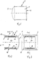
- the baking and roasting oven muffle 1 'designed as a hollow body unit 1' according to the drawing consists of an inner and an outer tub body 2 and 3, which are separated from one another by a cavity 4.
- the inner and outer tub body 2 and 3 are suitably made of stainless steel sheet in the deep-drawing process. Stainless steel sheet is particularly well suited for this purpose due to its high heat reflection.
- the rear wall 5 of the double-walled baking and roasting oven muffle 1 ' is advantageously curved outwards or designed as a spherical section. Due to the hemisphere shape of the Muffle rear wall 5, for example in hot air operation, results in a particularly favorable deflection of the hot air conveyed through the baking and roasting space 10.
- the side walls of the muffle hollow body unit 1 can be curved outwards in order to increase the strength or rigidity.
- the oven muffle 1 and thus its baking and roasting space 10 can be closed by a door, not shown, which contains all the essential functional elements for operating the oven muffle.
- the front or loading opening 6 for the baking and roasting space 10 of the oven muffle 1 ' has a moving, vertical muffle frame 7 which contains the two bearings 8 for articulating the aforementioned muffle door.
- a bottom heat and a top heat radiator 11 and 12 are held in corresponding brackets 13, 14.
- the tub-like oven muffle 1 ' has an air-free cavity 4 by evacuation, which is designed to be gas-tightly closed.
- the flange edges 15 of the inner and outer tub bodies 2 and 3 are tightly and firmly connected to one another by welding.
- a heat-insulating support material 17 made of glass fiber material or the like is arranged or enclosed between them, which, in addition to its thermal insulation, is also to prevent the jacket area 16 of the jacket area 16 from being evacuated from the oven muffle cavity 4 inner tub body is pressed against the jacket region 16 'of the outer tub body 3 or vice versa.
- the arched rear wall 5 of the two tub bodies 2 and 3 withstands the usual pressures due to its special shape and therefore does not require any additional support material in the cavity 4 located therebetween.
- the above-described design of the oven muffle is characterized by excellent insulation values, because on the one hand the use of stainless steel sheet a high heat reflection towards the baking chamber 10 is achieved and on the other hand an above-average heat insulation is ensured by the evacuation of the furnace muffle hollow body and the accommodation of an additional insulating material 17 in the jacket area 16, 16 'of the two tub bodies 2 and 3. Since the additional insulating material 17 is enclosed in the hollow-body furnace muffle, it is neither possible for the pollutants in the insulating material to evaporate, nor do insulating fiber particles get into the kitchen atmosphere.
Landscapes
- Engineering & Computer Science (AREA)
- Chemical & Material Sciences (AREA)
- Combustion & Propulsion (AREA)
- Mechanical Engineering (AREA)
- General Engineering & Computer Science (AREA)
- Muffle Furnaces And Rotary Kilns (AREA)
Abstract
Description
- Die Erfindung betrifft eine Back- und Bratofenmuffel nach dem Oberbegriff des Patentanspruchs 1.
- Bei der thermischen Isolation von derartigen Back- und Bratofenmuffeln werden in der Regel derzeit immer noch Glas- oder Steinwollematten eingesetzt. Nachteilig bei einer solchen Isoliermethode ist, daß Gesundheitsgefährdungen des Montagepersonals nicht auszuschließen sind, weil sich während der Montage Glasfaserpartikel aus den Isoliermatten lösen und die Atmenluft belasten. Darüber hinaus sind die Wärmeisoliereigenschaften solcher Dämmstoff-Matten nicht optimal, so daß die Wärmeabstrahlung bei solcher Art ausgerüsteten Backofenmuffeln noch immer sehr hoch ist.
- Aus der DE 36 19 974 C2 ist eine Back- und Bratofenmuffel der in Rede stehenden Art bekannt, die aus einer kompakten Hohlkörper-Einheit besteht. Der Hohlraum dieser Hohlkörper-Einheit ist mit der thermischen Ofenmuffel-Isolierung ausgefüllt, die in diesem Fall jedoch aus einer Isoliermasse in Pulverform besteht.
- Der Erfindung liegt die Aufgabe zugrunde, eine Back- und Bratofenmuffel zu schaffen, die gegenüber dem Stand der Technik verbesserte Wärmeisoliereigenschaften aufweist sowie eine erhebliche Einsparung an Primärenergie zuläßt.
- Die Lösung dieser Aufgabe gemäß der Erfindung ist dem kennzeichnendem Teil des Patentanspruchs 1 zu entnehmen.
- Vorteilhafte weitere Ausgestaltungen des Gegenstandes der Erfindung sind in den Unteransprüchen angegeben.
- Durch die vorgeschlagene Ausgestaltung der Back- und Bratofenmuffel ergeben sich die Vorteile einer überdurchschnittlichen energiesparenden Betriebsweise eines damit ausgerüsteten Back- und Bratofens.
- Ein Ausführungsbeispiel der Erfindung ist in der Zeichnung dargestellt und wird anhand dieser nachfolgend näher beschrieben.
- Es zeigen:
- Fig. 1
- eine Back- und Bratofenmuffel in einer Seitenansicht,
- Fig. 2
- diese Back- und Bratofenmuffel im Schnitt,
- Fig. 3
- eine Vorderansicht der Back- und Bratofenmuffel gemäß Fig. 1.
- Die als Hohlkörpereinheit 1 ausgebildete Back- und Bratofenmuffel 1' nach der Zeichnung besteht aus einem inneren und einem äußeren Bottichkörper 2 und 3, die durch einen Hohlraum 4 voneinander getrennt sind. Der innere und der äußere Bottichkörper 2 und 3 sind zweckmäßig aus Edelstahlblech im Tiefziehverfahren hergestellt. Edelstahlblech ist für diesen Verwendungszweck aufgrund seiner hohen Wärmereflektion besonders gut geeignet. Die Rückwand 5 der doppelwandigen Back- und Bratofenmuffel 1' ist in vorteilhafter Weise nach außen gewölbt bzw. als Kugelabschnitt ausgebildet. Durch die Halbkugelform der Muffelrückwand 5 ergibt sich z.B. bei Heißluftbetrieb eine besonders günstige Umlenkung der durch den Back- und Bratraum 10 geförderten Heißluft. Es wäre auch denkbar, die Seitenwände der Muffel-Hohlkörpereinheit 1 ebenfalls nach außen gewölbt auszubilden, um dadurch die Festigkeit bzw. Steifigkeit zu erhöhen. Frontseitig ist die Ofenmuffel 1 und damit deren Back- und Bratraum 10 durch eine nicht dargestellte Tür verschließbar, die sämtliche wesentlichen Funktionselemente zum Betrieb der Ofenmuffel enthält. Die Frontseite bzw. Beschickungsöffnung 6 für den Back- und Bratraum 10 der Ofenmuffel 1' weist einen umziehenden, vertikalen Muffelrahmen 7 auf, der die beiden Lagerungen 8 zum Anlenken der vorgenannten Muffeltür enthält. Im Back- und Bratraum 10 ist ein Unterhitze- und ein Oberhitze-Heizkörper 11 bzw. 12 in entsprechenden Haltewinkel 13, 14 gehaltert. Die bottichartige Ofenmuffel 1' weist durch Evakuierung einen luftleeren Hohlraum 4 auf, der gasdicht verschlossen ausgebildet ist. Zu diesem Zweck sind die Flanschränder 15 des inneren und des äußeren Bottichkörpers 2 und 3 durch Verschweißen dicht und fest miteinander verbunden. Zwischen den beiden Mantelbereichen 16,16' der Hohlkörper-Ofenmuffel 1' ist ein wärmedämmendes Stützmaterial 17 aus Glasfaserwerkstoff oder dergleichen angeordnet bzw. dazwischen eingeschlossen, das neben seiner Wärmedämmung auch verhindern soll, daß durch die Evakuierung des Ofenmuffel-Hohlraumes 4 der Mantelbereich 16 des inneren Bottichkörpers gegenüber dem Mantelbereich 16' des äußeren Bottichkörpers 3 oder umgekehrt gedrückt wird. Die gewölbt ausgebildete Rückwand 5 der beiden Bottichkörper 2 und 3 hält auf Grund ihrer speziellen Formgestaltung den üblichen Drücken stand und benötigt deshalb in dem dazwischen befindlichen Hohlraum 4 kein zusätzliches Stützmaterial.
- Die vorbeschriebene Ausbildung der Ofenmuffel zeichnet sich durch hervorragende Isolierwerte aus, da einerseits durch den Einsatz von Edelstahlblech eine hohe, zum Backraum 10 hin gerichtete Wärmereflektion erreicht wird und andererseits durch die Evakuierung des Ofenmuffel-Hohlkörpers und Unterbringung eines zusätzlichen Isoliermaterials 17 im Mantelbereich 16,16' der beiden Bottichkörper 2 und 3 eine überdurchschnittlich gute Wärmedämmung sichergestellt wird. Da das zusätzliche Isoliermaterial 17 in der Hohlkörper-Ofenmuffel eingeschlossen ist, ist weder ein Ausdampfen von im Isoliermaterial befindlichen Schadstoffen möglich noch gelangen Isolierfaser-Partikel in die Küchenatmosphäre.
Claims (6)
- Back- und Bratofenmuffel (1'), bestehend aus einer kompakten doppelwandigen Hohlkörpereinheit (1) mit einer thermischen Isolierung in deren Hohlraum,
gekennzeichnet durch folgende Merkmale:- der Hohlraum (4) der bottichartigen Hohlkörpereinheit (1) ist evakuiert und gasdicht verschlossen ausgebildet- die Rückwand (5) der bottichartigen Hohlkörpereineit (1) ist nach außen gewölbt bzw. als Kugelabschnitt ausgeformt,- im Hohlraum (4) im Mantelbereich (16,16') der Hohlkörpereinheit (1) ist ein wärmedämmendes Stützmaterial (17) vorgesehen. - Back- und Bratofenmuffel nach Anspruch 1, dadurch gekennzeichnet, daß der Innen- und der Außenbottich (2,3) der Hohlkörpereinheit (1) aus Edelstahlblech hergestellt sind.
- Back- und Bratofenmuffel nach Anspruch 1, dadurch gekennzeichnet, daß die Flanschränder (15) des Innen- und Außenbottichs (2,3) der Hohlkörpereinheit (1) miteinander verschweißt sind.
- Back- und Bratofenmuffel nach Anspruch 3, dadurch gekennzeichnet, daß die Verschweißung der Flanschränder als Rollnaht ausgeführt ist.
- Back- und Bratofenmuffel nach Anspruch 4, dadurch gekennzeichnet, daß mit dem Flanschrand (15) des Hohlkörpers (1) ein einen Türanschlag bildender Muffelrahmen (7) verbunden ist.
- Back- und Bratofenmuffel nach Anspruch 1 oder 2, dadurch gekennzeichnet, daß die Hohlkörpereinheit (1) gewölbt ausgebildete Seitenwände aufweist.
Applications Claiming Priority (2)
| Application Number | Priority Date | Filing Date | Title |
|---|---|---|---|
| DE19519407A DE19519407A1 (de) | 1995-05-26 | 1995-05-26 | Back- und Bratofenmuffel |
| DE19519407 | 1995-05-26 |
Publications (2)
| Publication Number | Publication Date |
|---|---|
| EP0744580A1 true EP0744580A1 (de) | 1996-11-27 |
| EP0744580B1 EP0744580B1 (de) | 1998-11-18 |
Family
ID=7762975
Family Applications (1)
| Application Number | Title | Priority Date | Filing Date |
|---|---|---|---|
| EP96107716A Expired - Lifetime EP0744580B1 (de) | 1995-05-26 | 1996-05-15 | Back- und Bratofenmuffel |
Country Status (2)
| Country | Link |
|---|---|
| EP (1) | EP0744580B1 (de) |
| DE (2) | DE19519407A1 (de) |
Cited By (2)
| Publication number | Priority date | Publication date | Assignee | Title |
|---|---|---|---|---|
| EP0987497A1 (de) * | 1998-09-15 | 2000-03-22 | BSH Bosch und Siemens Hausgeräte GmbH | Backofenmuffel mit thermischer Isolierung |
| US12016105B2 (en) | 2019-11-25 | 2024-06-18 | Bsh Home Appliances Corporation | Home appliance cavity |
Citations (4)
| Publication number | Priority date | Publication date | Assignee | Title |
|---|---|---|---|---|
| DE3619974A1 (de) * | 1986-06-13 | 1987-12-17 | Licentia Gmbh | Back- und bratofenmuffel |
| EP0261033A1 (de) * | 1986-09-18 | 1988-03-23 | L'air Liquide, Societe Anonyme Pour L'etude Et L'exploitation Des Procedes Georges Claude | Isolierende Struktur |
| FR2614388A1 (fr) * | 1987-04-22 | 1988-10-28 | Micropore International Ltd | Procede de fabrication d'un materiau calorifuge pour utilisation a tempe |
| FR2620521A1 (fr) * | 1987-09-15 | 1989-03-17 | Licentia Gmbh | Moufle de four a cuire et a rotir |
-
1995
- 1995-05-26 DE DE19519407A patent/DE19519407A1/de not_active Withdrawn
-
1996
- 1996-05-15 DE DE59600827T patent/DE59600827D1/de not_active Expired - Fee Related
- 1996-05-15 EP EP96107716A patent/EP0744580B1/de not_active Expired - Lifetime
Patent Citations (4)
| Publication number | Priority date | Publication date | Assignee | Title |
|---|---|---|---|---|
| DE3619974A1 (de) * | 1986-06-13 | 1987-12-17 | Licentia Gmbh | Back- und bratofenmuffel |
| EP0261033A1 (de) * | 1986-09-18 | 1988-03-23 | L'air Liquide, Societe Anonyme Pour L'etude Et L'exploitation Des Procedes Georges Claude | Isolierende Struktur |
| FR2614388A1 (fr) * | 1987-04-22 | 1988-10-28 | Micropore International Ltd | Procede de fabrication d'un materiau calorifuge pour utilisation a tempe |
| FR2620521A1 (fr) * | 1987-09-15 | 1989-03-17 | Licentia Gmbh | Moufle de four a cuire et a rotir |
Cited By (2)
| Publication number | Priority date | Publication date | Assignee | Title |
|---|---|---|---|---|
| EP0987497A1 (de) * | 1998-09-15 | 2000-03-22 | BSH Bosch und Siemens Hausgeräte GmbH | Backofenmuffel mit thermischer Isolierung |
| US12016105B2 (en) | 2019-11-25 | 2024-06-18 | Bsh Home Appliances Corporation | Home appliance cavity |
Also Published As
| Publication number | Publication date |
|---|---|
| EP0744580B1 (de) | 1998-11-18 |
| DE19519407A1 (de) | 1996-11-28 |
| DE59600827D1 (de) | 1998-12-24 |
Similar Documents
| Publication | Publication Date | Title |
|---|---|---|
| EP1208339B1 (de) | Wärmeisolierende wandung | |
| DE69408521T2 (de) | Kästen bestehend aus vakuumisolierten Wänden eines Kühl- oder Gefrierschranks | |
| DE2911416A1 (de) | Element zur waermeisolation | |
| EP1678091A1 (de) | Verfahren zum herstellen eines glasformteiles mit mindestens einem abgewinkelten schenkel | |
| EP0744580B1 (de) | Back- und Bratofenmuffel | |
| DE4028743A1 (de) | Backofen mit einer backmuffel | |
| EP1114960A2 (de) | Doppelwandiger Isolierkörper und Verfahren zu seiner Herstellung | |
| DE10344444B4 (de) | Verfahren zum partiellen Umformen von Glasplatten, Glas- oder Glaskeramikplatte mit partiell umgeformten Teilbereichen und Verwendung dieser Platte | |
| DE2545531C3 (de) | Backofentür mit einem Sichtfenster | |
| DE19519409C2 (de) | Back- und Bratofenmuffel | |
| DE3619974C2 (de) | ||
| DE1134483B (de) | Verfahren zur Zurueckhaltung der Erwaermung bestimmter Teile einer zu biegenden Glasscheibe und Biegeform hierfuer | |
| DE2855032C2 (de) | Tür zum Verschließen des Garraumes eines Mikrowellenofens | |
| DE4031893A1 (de) | Tuer fuer einen ofen zum garen oder erwaermen von nahrungsmitteln mittels mikrowellen | |
| DE19935836C2 (de) | Gargerät mit einem Dichtungsprofil und entsprechendes Dichtungsprofil | |
| DE102014217642B4 (de) | Gargerät mit einer Flanschgesamtfläche | |
| EP1094277B1 (de) | Backofen mit Backofentür-Glasscheibe | |
| AT255050B (de) | Verfahren zur Herstellung eines doppelwandigen Koch-, Brat- und Backgefäßes | |
| DE2854993C2 (de) | Tür zum Verschließen des Garraumes eines Mikrowellenofens | |
| DE19801079A1 (de) | Kamin oder Ofen für den Hausbereich | |
| DE3137992C2 (de) | ||
| DE29923921U1 (de) | Gargerät mit einem Dichtungsprofil und entsprechendes Dichtungsprofil | |
| DE10304281B4 (de) | Backofentür | |
| DE19822159A1 (de) | Mit einer Wasserkühlung versehenes Gefäß für die Behandlung von flüssigem Stahl | |
| DE2811941C2 (de) | Tür für den Garraum eines Mikrowellenherdes |
Legal Events
| Date | Code | Title | Description |
|---|---|---|---|
| PUAI | Public reference made under article 153(3) epc to a published international application that has entered the european phase |
Free format text: ORIGINAL CODE: 0009012 |
|
| AK | Designated contracting states |
Kind code of ref document: A1 Designated state(s): DE FR GB IT SE |
|
| 17P | Request for examination filed |
Effective date: 19961220 |
|
| GRAG | Despatch of communication of intention to grant |
Free format text: ORIGINAL CODE: EPIDOS AGRA |
|
| GRAG | Despatch of communication of intention to grant |
Free format text: ORIGINAL CODE: EPIDOS AGRA |
|
| GRAH | Despatch of communication of intention to grant a patent |
Free format text: ORIGINAL CODE: EPIDOS IGRA |
|
| 17Q | First examination report despatched |
Effective date: 19980506 |
|
| GRAH | Despatch of communication of intention to grant a patent |
Free format text: ORIGINAL CODE: EPIDOS IGRA |
|
| GRAA | (expected) grant |
Free format text: ORIGINAL CODE: 0009210 |
|
| AK | Designated contracting states |
Kind code of ref document: B1 Designated state(s): DE FR GB IT SE |
|
| REF | Corresponds to: |
Ref document number: 59600827 Country of ref document: DE Date of ref document: 19981224 |
|
| GBT | Gb: translation of ep patent filed (gb section 77(6)(a)/1977) |
Effective date: 19981216 |
|
| ET | Fr: translation filed | ||
| PG25 | Lapsed in a contracting state [announced via postgrant information from national office to epo] |
Ref country code: SE Free format text: LAPSE BECAUSE OF NON-PAYMENT OF DUE FEES Effective date: 19990516 |
|
| PLBE | No opposition filed within time limit |
Free format text: ORIGINAL CODE: 0009261 |
|
| STAA | Information on the status of an ep patent application or granted ep patent |
Free format text: STATUS: NO OPPOSITION FILED WITHIN TIME LIMIT |
|
| 26N | No opposition filed | ||
| EUG | Se: european patent has lapsed |
Ref document number: 96107716.1 |
|
| PG25 | Lapsed in a contracting state [announced via postgrant information from national office to epo] |
Ref country code: FR Free format text: LAPSE BECAUSE OF NON-PAYMENT OF DUE FEES Effective date: 20000131 |
|
| PG25 | Lapsed in a contracting state [announced via postgrant information from national office to epo] |
Ref country code: DE Free format text: LAPSE BECAUSE OF NON-PAYMENT OF DUE FEES Effective date: 20000301 |
|
| REG | Reference to a national code |
Ref country code: FR Ref legal event code: ST |
|
| PG25 | Lapsed in a contracting state [announced via postgrant information from national office to epo] |
Ref country code: GB Free format text: LAPSE BECAUSE OF NON-PAYMENT OF DUE FEES Effective date: 20000515 |
|
| GBPC | Gb: european patent ceased through non-payment of renewal fee |
Effective date: 20000515 |
|
| PG25 | Lapsed in a contracting state [announced via postgrant information from national office to epo] |
Ref country code: IT Free format text: LAPSE BECAUSE OF NON-PAYMENT OF DUE FEES Effective date: 20050515 |