EP0744681A2 - Soupage de régulation de débit - Google Patents
Soupage de régulation de débit Download PDFInfo
- Publication number
- EP0744681A2 EP0744681A2 EP96105020A EP96105020A EP0744681A2 EP 0744681 A2 EP0744681 A2 EP 0744681A2 EP 96105020 A EP96105020 A EP 96105020A EP 96105020 A EP96105020 A EP 96105020A EP 0744681 A2 EP0744681 A2 EP 0744681A2
- Authority
- EP
- European Patent Office
- Prior art keywords
- medium
- piston
- measuring
- throttle
- differential pressure
- Prior art date
- Legal status (The legal status is an assumption and is not a legal conclusion. Google has not performed a legal analysis and makes no representation as to the accuracy of the status listed.)
- Granted
Links
- 239000000314 lubricant Substances 0.000 claims abstract description 6
- 230000001105 regulatory effect Effects 0.000 claims abstract description 4
- 230000009471 action Effects 0.000 claims abstract description 3
- 238000006073 displacement reaction Methods 0.000 claims description 8
- 239000007788 liquid Substances 0.000 claims description 5
- 230000009969 flowable effect Effects 0.000 claims description 4
- 230000006835 compression Effects 0.000 claims description 2
- 238000007906 compression Methods 0.000 claims description 2
- 230000000903 blocking effect Effects 0.000 claims 2
- 238000011109 contamination Methods 0.000 description 6
- 230000008901 benefit Effects 0.000 description 3
- 230000008859 change Effects 0.000 description 3
- 238000004140 cleaning Methods 0.000 description 3
- 239000000356 contaminant Substances 0.000 description 3
- 230000000694 effects Effects 0.000 description 3
- 239000012535 impurity Substances 0.000 description 3
- 230000002349 favourable effect Effects 0.000 description 2
- 241000920033 Eugenes Species 0.000 description 1
- 239000012141 concentrate Substances 0.000 description 1
- 238000005516 engineering process Methods 0.000 description 1
- 239000010720 hydraulic oil Substances 0.000 description 1
- 230000003993 interaction Effects 0.000 description 1
- 238000005461 lubrication Methods 0.000 description 1
- 239000003921 oil Substances 0.000 description 1
- 230000009467 reduction Effects 0.000 description 1
Images


Classifications
-
- G—PHYSICS
- G05—CONTROLLING; REGULATING
- G05D—SYSTEMS FOR CONTROLLING OR REGULATING NON-ELECTRIC VARIABLES
- G05D7/00—Control of flow
- G05D7/01—Control of flow without auxiliary power
- G05D7/0146—Control of flow without auxiliary power the in-line sensing element being a piston or float without flexible member or spring
Definitions
- the invention relates to a flow control valve for a flowable medium, for example a lubricant, with an adjustable measuring throttle and with a differential pressure regulator which, with the aid of a differential pressure piston, adjusts a differential pressure throttle whose cross-section is variable to a cross-sectional value such that the pressure drop of the medium at the measuring throttle a constant value is maintained, the differential pressure regulator of the measuring throttle being connected in parallel (preamble of claim 1).
- This ensures that the flowable medium, for example a lubricant, flows with a constant amount per unit of time due to the constant pressure difference at the measuring throttle.
- Such flow control valves are used, for example, with a lubricant for central lubrication systems.
- Another application example is the operation of hydraulic systems with hydraulic oil.
- a flow control valve according to the preamble of claim 1 is known from DE-OS 22 41 397.
- the measuring choke is formed there by a disk with a triangular opening, which can be rotated to form a counter disk fixed to the housing.
- the differential pressure regulator also called pressure compensator
- the disadvantage here is that contamination of this measuring throttle results in a reduction in the volume of the medium flowing through and that this contamination can only be removed in the known arrangement by switching off the system and disassembling and cleaning the flow control valve.
- a volume flow controller VUA-B is described in a printed sheet 0017.10.81 from EUGEN WOERNER GmbH & Co., Am Eichamt 8, 97877 Wertheim, in which a measuring section consisting of two measuring throttles and a differential pressure controller (pressure compensator) are provided.
- a measuring section consisting of two measuring throttles and a differential pressure controller (pressure compensator) are provided.
- pressure compensator is not parallel to the input and output of the measuring section, but is only connected in parallel to the throttle of this measuring section on the output side. This means that the same pressure difference cannot be maintained across the entire measuring section.
- the task or problem of the invention is first of all to improve a flow control valve according to the arrangement of the preamble of claim 1 in such a way that when impurities are fixed in the measuring throttle, they can be automatically flushed out of the medium.
- the measuring throttle connected in parallel with the differential pressure regulator is a measuring throttle section consisting of two spacing-apart measuring throttles, that each of these measuring throttles has a passage opening which can be changed in cross-section for the Medium has and that a control part is provided which is adjustable with the aid of the pressure of the medium prevailing within the measuring throttle section, the control part changing the passage cross sections of both measuring throttles according to its position.
- the above-mentioned effect is to be made possible when the medium flows in a streamlined manner.
- two openings are provided in the wall of a control piston having a cavity and forming the control part, these openings being spaced apart from one another in the longitudinal direction of the control piston so that there is a first opening connects the inflow of the medium into the measuring throttle section with the cavity of the control piston, while the second opening connects the cavity of the control piston with the outflow of the medium from the measuring throttle section so that the control piston is displaceable in its longitudinal direction on guides fixed to the housing, which together with the openings form the two measuring throttles, each of the guides according to the displacement position of the control piston opens the opening belonging to it, partially blocks or completely blocks, and that means are provided with which the displacement position of the control piston is in accordance with the pressure difference nz of the medium between the two throttles.
- the passage cross section of the inlet-side measuring throttle of the section is reduced by establishing contamination of the medium, less medium flows through there per unit of time than before. This means that the pressure of the flowing medium becomes lower. This results in a corresponding displacement of the control piston in the direction of the flowing medium.
- the passage cross section of the soiled measuring throttle is increased and the inflowing medium can wash away the contaminants.
- the measuring choke on the outlet side ie the measuring throttle lying in the direction of the flowing medium, reduces its passage cross section due to impurities. This causes the control piston to move towards the medium flowing in, since the pressure in front of the throttle increases.
- the passage cross section of the output throttle is enlarged and the medium can wash away the contaminants.
- a pressure reducing valve known as a throttle
- the flow rate of a liquid is proportional to the pressure of the flowing liquid.
- a displaceable piston which has a taper at one end, the flow cross-section is changed when the piston is displaced in proportion to the pressure.
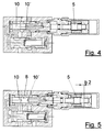
- FIGS. 1 to 5 each relate to the structurally identical arrangement, but show them in different functional positions.
- the invention will first be explained with reference to FIG. 2.
- the reference numerals used therein also apply to the same components in FIGS. 1, 3 to 5.
- This embodiment of the invention has a housing 1 with an inlet 2 and an outlet 3 of the flowable medium, e.g. of a lubricant.
- An adjusting piston 4 is provided which can be displaced in the direction of the double arrow A by an adjusting screw 5 or under the action of a spring 6. This changes the size of a cavity 8 within a control piston 7, as can be seen from a comparison of FIG. 3 on the one hand with FIG. 4 and FIG. 5 on the other hand.
- FIGS. 4 and 5 For this purpose, reference is also made to the explanations for FIGS. 4 and 5.
- the actuating piston 4 is also fixed to the housing, but can be displaced in its position relative to the housing 1 in the longitudinal direction B-B of the regulating piston 7 and thus of the double arrow A with the aid of the screw adjustment 5 and the thread 5 '.
- the printing directions D2 and D3 are opposite to the printing direction D1.
- the differential pressure controller ensures a constant pressure difference between the inlet and outlet of the measuring throttle section explained above.
- the cross section of the opening 10 is partially clogged by contamination of the medium and thus the effective passage cross section for the medium is reduced accordingly, this has the consequence that in the cavity 8 and thus via the bore 18 and the annular space 20 on the annular end face 24 of the control piston 7, the pressure D2 is reduced.
- the passage cross section of the opening 10 is accordingly increased accordingly and the medium flowing through can wash away the contamination.
- the inflowing medium passes from the first annular space 14 and the beginning of the line 15 via a branch 15 ′′ into a space 21 and presses there according to the arrow D4 onto the end face of the piston of the differential pressure regulator 11 which is displaceably mounted in the housing 1
- Oil emerging in the third annular space 20 flows via a line 28 and a bore 29 into a space 30 in which it presses on the other end face 31 of the piston of the differential pressure regulator 11 according to arrow D5.
- a compression spring 32 is provided, which also presses on the end face 31 according to the arrow D6.
- the pressure 6 exerted by the spring determines the respective position of the differential pressure piston 11 as a function of the pressure variables D4 and D5.
- the positioning piston 4 with its extension 4 ' is positioned by means of the adjusting screw 5 so that the volume of the cavity 8 is relatively large (setting b1 of the adjusting screw in FIGS. 1 to 3) 5, the volume of the cavity 8 is set smaller (setting b2 in FIG. 5), so that compared to FIG. 3, only a smaller cross-sectional area of the openings 10, 10 'is available for the passage of the medium .
- the adjusting screw 5 according to FIG. 4 is in the position, there is no longer any cross section of the openings 10, 10 'for the passage of the medium. This is the volume zero position.
- the regulation then begins with the pressure of the inflowing medium.
- the shortness of the throttle sections can be achieved by forming the openings 10, 10 'in a corresponding triangular shape. This is a preferred but not exclusive embodiment of the invention.
Landscapes
- Physics & Mathematics (AREA)
- General Physics & Mathematics (AREA)
- Engineering & Computer Science (AREA)
- Automation & Control Theory (AREA)
- Flow Control (AREA)
- Magnetically Actuated Valves (AREA)
- Safety Valves (AREA)
- Compression-Type Refrigeration Machines With Reversible Cycles (AREA)
- Steering Control In Accordance With Driving Conditions (AREA)
- Heat-Pump Type And Storage Water Heaters (AREA)
- Fluid-Driven Valves (AREA)
Priority Applications (1)
| Application Number | Priority Date | Filing Date | Title |
|---|---|---|---|
| SI9630171T SI0744681T1 (en) | 1995-05-20 | 1996-03-29 | Flow regulator valve |
Applications Claiming Priority (2)
| Application Number | Priority Date | Filing Date | Title |
|---|---|---|---|
| DE29508440U | 1995-05-20 | ||
| DE29508440U DE29508440U1 (de) | 1995-05-20 | 1995-05-20 | Stromregelventil |
Publications (3)
| Publication Number | Publication Date |
|---|---|
| EP0744681A2 true EP0744681A2 (fr) | 1996-11-27 |
| EP0744681A3 EP0744681A3 (fr) | 1996-12-11 |
| EP0744681B1 EP0744681B1 (fr) | 2000-03-01 |
Family
ID=8008377
Family Applications (1)
| Application Number | Title | Priority Date | Filing Date |
|---|---|---|---|
| EP96105020A Expired - Lifetime EP0744681B1 (fr) | 1995-05-20 | 1996-03-29 | Soupage de régulation de débit |
Country Status (5)
| Country | Link |
|---|---|
| EP (1) | EP0744681B1 (fr) |
| AT (1) | ATE190142T1 (fr) |
| DE (2) | DE29508440U1 (fr) |
| ES (1) | ES2144167T3 (fr) |
| SI (1) | SI0744681T1 (fr) |
Families Citing this family (2)
| Publication number | Priority date | Publication date | Assignee | Title |
|---|---|---|---|---|
| DE19924691A1 (de) * | 1999-05-28 | 2000-11-30 | Mannesmann Rexroth Ag | Hydraulisches Stromregelventil |
| DE10145959C2 (de) * | 2001-09-18 | 2003-10-30 | Fraunhofer Ges Forschung | Stromregelventil |
Family Cites Families (6)
| Publication number | Priority date | Publication date | Assignee | Title |
|---|---|---|---|---|
| US3112764A (en) * | 1960-10-28 | 1963-12-03 | Bendix Corp | Flow-regulating valve |
| DE1498280A1 (de) * | 1965-03-13 | 1968-11-21 | Bosch Gmbh Robert | Stromregelventil |
| CH505325A (de) * | 1969-03-17 | 1971-03-31 | Oerlikon Buehrle Ag | Drossel |
| DE2241397A1 (de) * | 1972-08-23 | 1974-02-28 | Hans Schiedrum Maschinenfabrik | Hydraulisches stromregelventil |
| DE2807542C2 (de) * | 1978-02-22 | 1986-12-11 | Herion-Werke Kg, 7012 Fellbach | Stromregelventil |
| FR2651341B1 (fr) * | 1989-08-24 | 1993-12-24 | Barmag Ag | Regulateur de debit ou de pression. |
-
1995
- 1995-05-20 DE DE29508440U patent/DE29508440U1/de not_active Expired - Lifetime
-
1996
- 1996-03-29 ES ES96105020T patent/ES2144167T3/es not_active Expired - Lifetime
- 1996-03-29 EP EP96105020A patent/EP0744681B1/fr not_active Expired - Lifetime
- 1996-03-29 AT AT96105020T patent/ATE190142T1/de not_active IP Right Cessation
- 1996-03-29 SI SI9630171T patent/SI0744681T1/xx unknown
- 1996-03-29 DE DE59604517T patent/DE59604517D1/de not_active Expired - Fee Related
Also Published As
| Publication number | Publication date |
|---|---|
| DE29508440U1 (de) | 1996-09-19 |
| ES2144167T3 (es) | 2000-06-01 |
| SI0744681T1 (en) | 2000-08-31 |
| ATE190142T1 (de) | 2000-03-15 |
| EP0744681A3 (fr) | 1996-12-11 |
| EP0744681B1 (fr) | 2000-03-01 |
| DE59604517D1 (de) | 2000-04-06 |
Similar Documents
| Publication | Publication Date | Title |
|---|---|---|
| DE60105849T2 (de) | Hydraulisches wegeventilsystem mit druckwaagen | |
| DE2733054C2 (de) | Vorrichtung zur Zufuhr von unter Druck stehendem Fluid | |
| DE69128882T2 (de) | Hydraulisches Steuersystem und Richtungsumschaltventile | |
| DE2702953C2 (fr) | ||
| DE69021212T2 (de) | Lastdruckwiederholungsschaltung. | |
| DE2904033A1 (de) | Steuergeraet fuer druckmittelbetaetigte vorrichtungen | |
| DE2858210C2 (de) | Einrichtung zum Ausgleich von Viskositätsverminderungen in der Stellvorrichtung einer Hydropumpe | |
| DE3515732C2 (fr) | ||
| DE3241751C2 (de) | Prioritätsventil für hydraulische Anlagen | |
| DE69222861T2 (de) | Hydraulische schaltung mit druckausgleichventil | |
| DE2916575A1 (de) | Durchflussregelschieber | |
| DE2601999C3 (de) | Anordnung zur Beeinflussung der Arbeitsmenge eines Servomotors | |
| DE3320047C2 (fr) | ||
| DE2804045C2 (fr) | ||
| EP0231804A2 (fr) | Soupape de réglage | |
| DE2648280A1 (de) | Lastdrucksteuerung | |
| DE3436246C2 (de) | Steuereinrichtung für einen hydraulisch betriebenen Verbraucher | |
| DE4025638C1 (fr) | ||
| DE3919175C2 (fr) | ||
| EP0744681B1 (fr) | Soupage de régulation de débit | |
| DE2151837C2 (de) | Hydraulische Steuervorrichtung für die lastunabhängige Druchflußregulierung zu einem Verbraucher | |
| DE2133715B2 (de) | Vorrichtung zum feststellen eines verschiebbaren hydraulischen steuerventils | |
| DE3009699A1 (de) | Schaltventil mit neutraler stellung | |
| DE3027819A1 (de) | Vorrichtung zur regelung einer verstellpumpe | |
| DE3327590A1 (de) | Vorrichtung zur regelung des druckes am ende einer abfuelleitung |
Legal Events
| Date | Code | Title | Description |
|---|---|---|---|
| PUAI | Public reference made under article 153(3) epc to a published international application that has entered the european phase |
Free format text: ORIGINAL CODE: 0009012 |
|
| PUAL | Search report despatched |
Free format text: ORIGINAL CODE: 0009013 |
|
| AK | Designated contracting states |
Kind code of ref document: A2 Designated state(s): AT DE ES FR IT |
|
| AX | Request for extension of the european patent |
Free format text: SI PAYMENT 960329 |
|
| AK | Designated contracting states |
Kind code of ref document: A3 Designated state(s): AT DE ES FR IT |
|
| AX | Request for extension of the european patent |
Free format text: SI PAYMENT 960329 |
|
| 17P | Request for examination filed |
Effective date: 19970507 |
|
| RAP1 | Party data changed (applicant data changed or rights of an application transferred) |
Owner name: BAIER & KOEPPEL GMBH & CO. |
|
| GRAG | Despatch of communication of intention to grant |
Free format text: ORIGINAL CODE: EPIDOS AGRA |
|
| 17Q | First examination report despatched |
Effective date: 19990427 |
|
| GRAG | Despatch of communication of intention to grant |
Free format text: ORIGINAL CODE: EPIDOS AGRA |
|
| GRAH | Despatch of communication of intention to grant a patent |
Free format text: ORIGINAL CODE: EPIDOS IGRA |
|
| GRAH | Despatch of communication of intention to grant a patent |
Free format text: ORIGINAL CODE: EPIDOS IGRA |
|
| GRAA | (expected) grant |
Free format text: ORIGINAL CODE: 0009210 |
|
| AK | Designated contracting states |
Kind code of ref document: B1 Designated state(s): AT DE ES FR IT |
|
| AX | Request for extension of the european patent |
Free format text: SI PAYMENT 19960329 |
|
| REF | Corresponds to: |
Ref document number: 190142 Country of ref document: AT Date of ref document: 20000315 Kind code of ref document: T |
|
| REF | Corresponds to: |
Ref document number: 59604517 Country of ref document: DE Date of ref document: 20000406 |
|
| ITF | It: translation for a ep patent filed | ||
| REG | Reference to a national code |
Ref country code: ES Ref legal event code: FG2A Ref document number: 2144167 Country of ref document: ES Kind code of ref document: T3 |
|
| ET | Fr: translation filed | ||
| PLBE | No opposition filed within time limit |
Free format text: ORIGINAL CODE: 0009261 |
|
| STAA | Information on the status of an ep patent application or granted ep patent |
Free format text: STATUS: NO OPPOSITION FILED WITHIN TIME LIMIT |
|
| 26N | No opposition filed | ||
| PGFP | Annual fee paid to national office [announced via postgrant information from national office to epo] |
Ref country code: FR Payment date: 20010319 Year of fee payment: 6 |
|
| PGFP | Annual fee paid to national office [announced via postgrant information from national office to epo] |
Ref country code: AT Payment date: 20010323 Year of fee payment: 6 |
|
| PGFP | Annual fee paid to national office [announced via postgrant information from national office to epo] |
Ref country code: ES Payment date: 20010326 Year of fee payment: 6 |
|
| PGFP | Annual fee paid to national office [announced via postgrant information from national office to epo] |
Ref country code: DE Payment date: 20010426 Year of fee payment: 6 |
|
| PG25 | Lapsed in a contracting state [announced via postgrant information from national office to epo] |
Ref country code: AT Free format text: LAPSE BECAUSE OF NON-PAYMENT OF DUE FEES Effective date: 20020329 |
|
| PG25 | Lapsed in a contracting state [announced via postgrant information from national office to epo] |
Ref country code: ES Free format text: LAPSE BECAUSE OF NON-PAYMENT OF DUE FEES Effective date: 20020330 |
|
| PG25 | Lapsed in a contracting state [announced via postgrant information from national office to epo] |
Ref country code: DE Free format text: LAPSE BECAUSE OF NON-PAYMENT OF DUE FEES Effective date: 20021001 |
|
| PG25 | Lapsed in a contracting state [announced via postgrant information from national office to epo] |
Ref country code: FR Free format text: LAPSE BECAUSE OF NON-PAYMENT OF DUE FEES Effective date: 20021129 |
|
| REG | Reference to a national code |
Ref country code: FR Ref legal event code: ST |
|
| REG | Reference to a national code |
Ref country code: ES Ref legal event code: FD2A Effective date: 20030410 |
|
| PG25 | Lapsed in a contracting state [announced via postgrant information from national office to epo] |
Ref country code: IT Free format text: LAPSE BECAUSE OF NON-PAYMENT OF DUE FEES;WARNING: LAPSES OF ITALIAN PATENTS WITH EFFECTIVE DATE BEFORE 2007 MAY HAVE OCCURRED AT ANY TIME BEFORE 2007. THE CORRECT EFFECTIVE DATE MAY BE DIFFERENT FROM THE ONE RECORDED. Effective date: 20050329 |