EP0744756A2 - Appareil de liage d'un faisceau de fils électriques - Google Patents
Appareil de liage d'un faisceau de fils électriques Download PDFInfo
- Publication number
- EP0744756A2 EP0744756A2 EP96108197A EP96108197A EP0744756A2 EP 0744756 A2 EP0744756 A2 EP 0744756A2 EP 96108197 A EP96108197 A EP 96108197A EP 96108197 A EP96108197 A EP 96108197A EP 0744756 A2 EP0744756 A2 EP 0744756A2
- Authority
- EP
- European Patent Office
- Prior art keywords
- heating
- harness
- bundling
- wire
- tape
- Prior art date
- Legal status (The legal status is an assumption and is not a legal conclusion. Google has not performed a legal analysis and makes no representation as to the accuracy of the status listed.)
- Withdrawn
Links
Images



Classifications
-
- B—PERFORMING OPERATIONS; TRANSPORTING
- B65—CONVEYING; PACKING; STORING; HANDLING THIN OR FILAMENTARY MATERIAL
- B65B—MACHINES, APPARATUS OR DEVICES FOR, OR METHODS OF, PACKAGING ARTICLES OR MATERIALS; UNPACKING
- B65B27/00—Bundling particular articles presenting special problems using string, wire, or narrow tape or band; Baling fibrous material, e.g. peat, not otherwise provided for
- B65B27/10—Bundling rods, sticks, or like elongated objects
- B65B27/105—Bundling rods, sticks, or like elongated objects by means of adhesive tape
-
- Y—GENERAL TAGGING OF NEW TECHNOLOGICAL DEVELOPMENTS; GENERAL TAGGING OF CROSS-SECTIONAL TECHNOLOGIES SPANNING OVER SEVERAL SECTIONS OF THE IPC; TECHNICAL SUBJECTS COVERED BY FORMER USPC CROSS-REFERENCE ART COLLECTIONS [XRACs] AND DIGESTS
- Y10—TECHNICAL SUBJECTS COVERED BY FORMER USPC
- Y10T—TECHNICAL SUBJECTS COVERED BY FORMER US CLASSIFICATION
- Y10T29/00—Metal working
- Y10T29/51—Plural diverse manufacturing apparatus including means for metal shaping or assembling
- Y10T29/5136—Separate tool stations for selective or successive operation on work
- Y10T29/5137—Separate tool stations for selective or successive operation on work including assembling or disassembling station
- Y10T29/5143—Separate tool stations for selective or successive operation on work including assembling or disassembling station and means to machine product
-
- Y—GENERAL TAGGING OF NEW TECHNOLOGICAL DEVELOPMENTS; GENERAL TAGGING OF CROSS-SECTIONAL TECHNOLOGIES SPANNING OVER SEVERAL SECTIONS OF THE IPC; TECHNICAL SUBJECTS COVERED BY FORMER USPC CROSS-REFERENCE ART COLLECTIONS [XRACs] AND DIGESTS
- Y10—TECHNICAL SUBJECTS COVERED BY FORMER USPC
- Y10T—TECHNICAL SUBJECTS COVERED BY FORMER US CLASSIFICATION
- Y10T29/00—Metal working
- Y10T29/53—Means to assemble or disassemble
- Y10T29/5313—Means to assemble electrical device
- Y10T29/53261—Means to align and advance work part
Definitions
- the present invention relates generally to an electrical wire harness binding apparatus which automatically binds a predetermined number of electrical harnesses together to form a bundle of harnesses.
- wire harnesses In the production of wire harnesses, it is common for a predetermined number of wire harnesses to be bound together manually with rubber bands at the wire portions thereof to form a bundle of harnesses. A number of bundles are then collected, packaged and transferred to a subsequent working station or a warehouse. This manual labor, however, cannot be performed at an increased efficiency and an incorrect number of wire harnesses are sometimes bound. Also, the removal of the rubber bands from the bundles of wire harnesses to unbind them for subsequent use is tedious work because the rubber bands are likely to catch on the terminals or connectors of the wire harnesses.
- Another object of the present invention is to provide a wire harness binding apparatus which can bind automatically binds the harness wires to form bundles of harnesses in a manner which permits the unbinding of such bundles with ease.
- an electrical wire harness binding apparatus which includes carrier means for carrying the wires of the harnesses sequentially; shifting means responsive to the number of harness wires carried by the carrier means for shifting the wires perpendicularly to the lateral direction in which the wires are laid; guide means for guiding the wires to binding positions; tape feeding-and-stretching means placed near the end of the guide means for feeding a binding tape across the guide means in opposition to the harness wires, thereby permitting the tape to wind around the wires collected in the guide means; upper and lower tape application means disposed downstream of the tape feeding-and-stretching means for applying the tape to opposite sides of the bundle of harness wires; drive means for driving the upper and lower heating-and pinching means toward each other; and cutting means for cutting the binding tape after application to the wire harness bundle.
- the present invention provides an apparatus for binding together any selected number of completed wire harnesses in which the wires are terminated with connector elements at opposite ends of the harnesses.
- the guide means may include pairs of elongated rails, one of which serves as a stationary guide and the other of which serves as a movable guide which is biased against the stationary guide.
- the harness wire shifting means may include a ram for urging the harness wires held between the guides to a tape-application position.
- the upper and lower heating-and-pinching means may each include first and second operative heating units and the cutting means may be placed between the first and second heating units in order to cut the tape between sealed areas of sequential application of tapes.
- a single heating-and-pinching set may be used which is driven into an operative position twice on opposite sides of the wire harness bundle. The cutting means may be placed in such a position that it may cut the tape between such two sealed areas.
- At least one of the sealed areas of the application tape may be formed in a manner such that it is easily separable to permit the unbinding of the bundle of harness wires. Such separable areas may be provided by melting and pinching the folding lengths of tape at selected points.
- the wire binding apparatus may also be used to apply various harness identifying indicia in alphanumeric form to represent lot numbers, manufacturing data or other similar information.
- the harness bundling apparatus of the present invention may be positioned downstream of a harness assembly machine which fashions the wire harnesses by affixing terminals or connectors to opposing ends of the harness wires.
- the carrier means of the present invention may encompass a transfer section of the harness assembly machine. When the carrier means collects a predetermined number of completed wire harnesses, the wires portions of the harnesses are shifted perpendicularly to the direction of the wires into a position where they can be received by the guide means. The wires are then held between the stationary and biased guides in a ready position for taping.
- thermo-adhesive, synthetic resin tape may be placed within the apparatus at levels above and below the guide means in the path of the wire harnesses, and the binding tape is then drawn from the upper roll and lower roll in a manner to stretch the tape. Once stretched, the wires are urged forward into abutting contact with the tapes, which art then wound around the wires so that adhesive surfaces thereof meet together on the rear side of the bundle of harness wires.
- the tape is positioned between the upper and lower heating-and-pinching means, which are then driven close toward other to thereby pinch the tapes together on the rear side of the bundle of harness wires.
- the heating-and-pinching means may includes a high-frequency, induction heating sealing unit or supersonic sealing unit in order to provide an effective sealing of tapes in two selected areas.
- the tapes are cut between the two sealed tape areas to provide a bundle of harness wires, which moves forward, while leaving a sealed tape area behind it in the harness wire path.
- the upper and lower tapes diverge from the sealed tape area in a standby position for winding about subsequent bundles of harness wires.
- One of the sealed areas is preferably a spot-sealed area, which is easily separable for unbinding by fingers.
- the spot-sealing may be effected to provide alphanumeric patterns for identification.
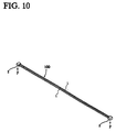
- FIG. 10 illustrates a completed wire harness 100 formed from two electrical wires 1 which are combined together by terminating terminals blocks, or connectors 2, to their opposing ends.
- Each terminal block 2 is preferably of the insulation displacement style, having at least one conductive spike or blade disposed inside of it, which pierces the exterior insulation of the wire 1 until it reaches and contacts the internal conductor of the wire (not shown) to effect a electrical connection between the terminal block 2 and the conductor of the insulated wire 1 as is known in the art.
- This type of termination is usually automatically performed by an automated terminating machine known in the art.
- wires are arranged in a parallel order, measured a specific distance, and cut to obtain a given length.
- the measured and cut wires are then terminated to terminal blocks or connectors at their opposing ends in order to form wire harnesses.
- Terminal blocks of different sizes may be used to combine two or more electrical wires into the completed wire harnesses 100.
- one terminal block may be applied to one set of ends of the wires, while the other ends of the wires are stripped. In other instances, one terminal block is applied to one set of ends of the wires, and two or more terminal blocks of different sizes are applied to the other ends of the wires.
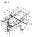
- the binding apparatus 110 is seen to include the following assemblies: carrier means A for carrying wire harnesses 100 sequentially; shifting means C for shifting these wire harnesses 100 in a direction perpendicular to the axes of the wires; parallel guide means B for guiding the harness wires 1 to sequential working positions; tape feeding-and-stretching means E (FIG.
- the carrier means A includes a portion of the transfer section or outlet of the aforementioned termination machine, which transfer section includes a pair of transfer guide extensions 11a and 11b, preferably spaced apart and generally parallel to each other.
- the termination machine wires are cut at given lengths and terminated and one of the transfer guide extensions 11a and 11b may be laterally moved (indicated by "b" in FIG. 1) so as to control the lateral space between the transfer guide extensions 11a, 11b, in accordance with the predetermined length of the wires.
- the harness wires 1 are moved perpendicularly relative to their axes (as indicated by "a") to be positioned at the outlet of the transfer guide extensions at regular time intervals in accordance with their production.
- a guide means B is preferably positioned downstream of the outlet of the transfer guide extensions 11a and 11b to receive the completed wire harnesses 100 in sequential order.
- the guide means B includes a pair of spaced apart, elongated, stationary guide members 12 of predetermined length and an elongated confronting spring-biased guide member 13 which is biased against the upper surface 12a of each stationary guide member 12.
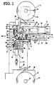
- Each biased guide member 13 is fixed to a pair of posts 14 which have a coil spring 16 wound therearound and compressed between an associated adjustable stop member 15 and the guide member 13, as best shown in FIG. 2.
- the biased guide members 13 are movable upwardly under the advancement of wire harnesses 100 through the guide means A.
- the guide means B is supported on the frame 10 of the harness binding apparatus 110.
- the shifting means C includes a flat plate 19 having two arms 18 integrally connected to opposing sides thereof. Each arm 18 has vertical and horizontal extensions 18b and 18a which cooperate to define a step 125 at its end.
- a drive unit D is operatively associated with the shifting means C and includes, as illustrated in FIG. 2, a longitudinal support 21 fixed to the apparatus frame 10, a horizontal pneumatic cylinder 22 fixed to the support 21 and a reciprocating slider 23 driven by the cylinder 22.
- the slider 23 is equipped with a vertical pneumatic cylinder 24 which effects upward and downward movement of the shifting means C.
- the shifting means C is operatively connected to the vertical cylinder 24 of the slider 23 via rods 24a which engage the plate 19 of the shifting means C.
- the shifting means C is movable from the original position (shown in solid lines) to the lower, start position "i,” shown in phantom in FIG. 2.
- the horizontal cylinder 22 then drives the shifting means C forward between the start position "i” and the final position "ii,” shown in phantom at the left of FIG. 2.
- the harnesses 100 produced at the outlet of the transfer section A reach a predetermined number
- the harnesses 100 are moved by the shifting means C, particularly the front risers 18b of the arms 18 thereof to shift the harness wires 1 thereof forward in a group in the direction indicated by "a.”
- the harness wires 1 are pinched between the stationary and biased guide members 12, 13 of the guide means B.
- the tape feeding-and-stretching means E includes two tape rolls F1, F2 spaced apart from each other.
- the upper tape roll F1 has a center axle 32 which is rotatably fixed to a vertical support 31 extending from the apparatus frame 10.
- the center axle 32 is rotatable against a predetermined load, and the tape Fa is pulled out from the upper tape roll F1, passing by guide rollers 33 and 34 and by an alignment roller 35 to reach the wire abutting position G which is located between the guide means B and interposed in the wire pathway.
- the lower tape roll F2 has a center axle 37, which is rotatably fixed to a support 36 extending from the apparatus frame 10.
- the center axle 37 is rotatable against a predetermined load, and the tape Fb thereon is pulled out from the lower tape roll 72, passing by guide rollers 38 and 39 and by an alignment pad 40 to reach the wire-abutting position G, where the tapes Fa and Fb meet together to be heated and melted on their adhesive sides in order to adhere them together to provide a forward sealing area as indicated by S2. (FIG. 5.)
- the guide rollers 33, 34, 38, 39, and the alignment roll 35 are rotatably fixed to the frame 10, as is the alignment pad 40.
- the binding tape is preferably a thermo-adhesive synthetic resin tape, such as polyacrylonitrile film.
- the upper and lower heating-and-pinching means H is located downstream of the wire-abutting position G.
- the harness wires 1 are moved forward by the shifting means C into abutting engagement with the forward sealed area S2 of the two binding tapes Fa and Fb. Further forward movement of the group of harness wires causes the tapes Fa and Fb to, in effect, wind around the harness wires 1 so that their adhesive surfaces mate together on the rear side of the bundle of harness wires 1 in alignment with and between the upper and lower heating-and-pinching means H.
- the lower assembly of the heating-and-pinching means H is disposed below the guide means B, and includes a pneumatic cylinder drive unit 42, fixed to a lateral support 41 of the apparatus frame 10.
- a heater assembly 45 is mounted to the piston rod 43 of drive unit 42 via an associated support plate 44 and has a heating element 53 embedded therein.
- a slot 45a is present in the heater assembly 45 between first and second heating pads 46, 47.
- These heating pads 46, 47 are preferably thermo-conductive metal plates.
- the support plate 44 of the heater assembly 45 may include a bolt 48 and a slidable pincher piece 49 slidably fixed thereto with a compression spring 51 wound thereabout between the support plate 44 and the pincher piece 49, thus imparting a constant upward force.
- the upper assembly of the heating-and-pinching means H is disposed above the guide means B.
- it includes a pneumatic cylinder drive unit 56 and 57 fixed to a lateral support 55 of the apparatus frame 10, and a reaction block 62 fixed to the piston rod 57 of drive unit 56 via associated support plate 58 and movable stage 61.
- the support plate 58 has a rod 59 passing therethrough, and the rod 59 is operatively connected to the movable stage 61 by a compression spring 67 wound therearound, thus exerting a constant downward force or the movable stage 61 as seen from FIG. 4.
- the movable stage 61 further has two guide rods 65 slidably fitted in the bearings 66 of the lateral support 59.
- the reaction block 62 has a slot 62a formed in its lower surface and first and second reaction, or contact pads, 63, 64 are fixed to the reaction block 62 on the opposite sides of the slot 62a.
- the heating-and-pinching means H has first and second sets of heating-and-pinching surfaces.
- the first set of heating-and-pinching surfaces includes the first heating pad 46 of the lower assembly and the first contact pad 63 of the upper assembly.
- a second set of heating-and-melting surfaces is made up by the second heating pad 41 of the lower assembly and the second contact pad 64 of the upper assembly.
- Those first and second sets are disposed downstream of the wire abutting position G, where the tapes Fa and fb wind around the electric wires 1 so that their adhesive surfaces meet together on the rear side of the bundle of electric wires 1.
- the support plate 58 of the upper assembly has an additional stud 68 fixed thereto, ad a slidable pincher piece 69 is fixed thereto and includes a compression spring 71 therearound, to exert a constant downward force on the slidable pincher 69.
- the support plate 58 has a knife holder 72 with a cutting knife 73 fixed thereto.
- the cutting knife 73 is received within and extends from the slot 62a of the upper assembly.
- the edge of the slot 45a of the lower heating element 45 is aligned with the cutting knife 73 to cooperate in shearing the tape.
- the mating area of tapes Fa and Fb located upstream of the bundle 120 of harness wires is pinched between the upper reaction blob 62 and the lower heating assembly 45 so that the first heating pad 46 and its opposing contact pad 63 heat and melt the mating areas of tapes Fa and Fb to form a first sealed area S1.
- the second heating pad 47 and its opposing contact pad 64 heat and melt the mating areas of tapes Fa and Fb to form a second sealed area S2.
- the first heating pad 46 or its opposing contact pad 63 may include minute projections distributed on its surface which, in effect, will form a sealed area that can be easily separated.
- the second heating pad 47 and its associated contact pad 64 of the second set have substantially flat surfaces which, in effect, form a sealed area of the binding tape that cannot be separated. Accordingly, the present invention bundles wire harnesses together with strips of tape which have separable and inseparable sealed areas S1 and S2 on opposite ends of the wire harness bundles 120.
- the knife 73 cuts the opposing tapes Fa and Fb between their respective separable and inseparable soiled areas S1 and S2 upstream of the bundle of harness wires, leaving an inseparable sealed area S2 it the wire abutting position G.
- the next group of harness wires 1 are then pushed into contact with the sealed area of tape so that the binding tape winds about the harness wires.
- the sealed area S2 is inseparable because otherwise the sealed area may become separated during the advancement of the harness wires.
- a rotatable arm 81 may be driven by a suitable drive means (not shown) to rotate about its pivot 82 in the direction indicated by the dashed arrow X.
- a suitable drive means not shown
- the arm 81 rotates to hold the harness wires 1 together as a group, thereby preventing any of the harness wires 1 from slipping off from the stationary and biased guide members 12, 13.
- the lower heating assembly 45 is raised by the lower cylinder drive 42, and the upper heating assembly 62 is lowered by the upper cylinder drive 56 so that the tapes Fa and Fb diverge from their second sealed area S2 at the wire abutting position G (FIG 6). This closes the trailing edge of the preceding group of harness wires and seals the leading edge of the subsequent group of harness wires.
- the harnesses 100 are directed to the guide means B via the transfer guide outlets 11a and 11b, and the harness wires thereof 1 are pinched between the stationary guide member 12a and the biased guide member 13. Almost all of the harness wires 1 thus transferred may be pushed in between the stationary and biased guide extensions 12, 13, but some of the harness wires 1 ride on the rear slanted surfaces "d" of the stationary guide members 12a. These harness wires 1, however, do not fall down because the transfer guide extensions 11a and 11b extend beyond the slanted surfaces "d" of the stationary guide 12a in an overlapping fashion.
- the driving unit D begins its cycle.
- the number of harness wires 1 appearing at the outlet of the carrier means A is determined in terms of terminating cycles of the termination machine, and when the number has reached its predetermined value, an electric control in the termination machine sends a signal to a like electric control in the wire binding apparatus 110, and the driving unit D begins transferring the harness wires to the wire abutting position G.
- the vertical cylinder unit 24 of the driving unit D lowers the arms 18 of the shifting means C to the position "i" indicated in phantom lines in FIG. 2. Then the horizontal cylinder unit 22 drives the slider 23 toward the position "ii” indicated in phantom in the longitudinal direction indicated by arrow "a.”
- the holding arm 81 preferably rotates in the direction indicated by arrow "x,” thereby preventing any harness wires 1 from falling off from the slanted surface "d" of the stationary guide members 12.
- the transfer guide extension 11b may be shifted laterally as indicated by "b” to adjust the lateral space between transfer guide extensions 11a, 11b to accommodate the harness wire lengths.
- the harness wires 1 arrive at the wire abutting position G where the upper and lower tapes Fa and Fb diverge from the second sealed area S2.
- the electric wires 1 are moved forward, causing the diverging tapes to, in effect, wind around the bundle of harness wires 1 so that their adhesive surfaces are brought together on the rear side of the bundle of harness wires 1, as seen in FIG. 5.
- the upper tape Fa is stretched and pays out via the alignment roll 35 whereas the lower tape Fb is stretched and pays at via the alignment pad 40.
- the wires 1 are pushed further forward by the arms 18 in the longitudinal direction "a" to the extent they reach the position "ii” and the harness wires leave the contact of stationary and biased guide members 12, 13 at whim point the trailing tape portion at the position in which the heating units 45, 62 confront each other.
- the trailing tape portion is heated and cut simultaneously, so that the rear side of the harness wire bundle is sealed to provide sealed area S1, and also cut to define another sealed area S2 behind it in place at the wire position G.
- the transfer means C Prior to the melting-and-cutting of the tape, the transfer means C returns to the original position "i" by the linear piston-and-cylinder unit 24.
- the lower piston-and-cylinder unit 42 raises the support plate 44 to bring the heating assembly 45 and the pinching piece 49 to the position shown in FIG. 6.
- the upper piston-and-cylinder unit 56 lowers the support plate 58.
- the upper and lower tapes Fa and Fb which are wound around the bundle of harness wires 1 by the forward movement of the bundle are pinched between the upper and lower opposed pinching pieces 69, 49, and contact between the contact pads 63, 64 and the heating pads 46, 47.
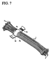
- the first sealed area S1 may, as shown in FIG. 7 include a plurality of distributed dots or perforations to provide an easily separable seal, whereas the second sealed area S2 is free of such spaces or voids, thus providing an inseparable seal.
- the heating-and-sealing of tapes Fa and Fb is effected in one step at the instant of pinching the tapes between the contact pads 63, 64 and heating pads 46, 47 during the descent of the support plate 58.
- the support plate 58 continues descending by the upper cylinder unit 56 after the contact pads 63 and 64 are pushed against the heating pads 46, 47, Then, the slidable rod 59 rises through the support plate 58 while compressing the spring 67.
- the binding tapes, as wrapped around the wire harness bundle are then cut between their first and second sealed areas S1 and S2 by the knife 73 as it enters the slot 45a of the lower heating unit 45.
- the lower heating unit 45 is lowered, and the upper heating unit 62 is raised to expose a taped bundle of harness virus.
- the remaining tapes Fa and Fb have been sealed together at the second sealed area S2 and diverge both upwardly and downwardly to remain in a standby position across the wire path to bind a subsequent set of harness wires.
- the bundled harness wires (FIG. 7) may be easily unbound at the point of delivery by pulling the tabs of the first sealed area S1 apart from each other.
- a single heating-and-pinching set may be used.
- the single set will be operated to provide a first scaled area.
- the bundle of harness wires is then shifted forward so the single set may be operated again to provide a second sealed area spaced from the first area.
- the bundle of wires are moved downstream and the wrapped tapes Fa and Fb are cut and separated between the first and second sealed areas S1 and S2.
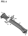
- FIG. 8 shows another example of a set of wire harnesses bound with tape in which the second sealed area S2 is inseparable and the first sealed area S1a is separable, having dots thereon in the form of alphanumeric patterns indicating the lot number, the manufacturing date or other indicia Sa.
- the dot-sealed area S1a can be easily broken by separating its opposite tabs apart from each other. If the dot-sealed area provides insufficient binding strength, an intermittent or very fine line seal Sb may be added for reinforcement.
- the tape is of semi-opaque film such as polyacrylonitrile film, it will be transparent when heated, thereby advantageously permitting its alphanumeric indications to be sharply visible.
- an alternate heating-and-pinching unit Ha can be seen to include upper and lower confronting units with the lower unit having first and second heating assemblies 91, 92 fixed to its base support 44, and a cutter blade 93 provided between the heating assemblies 91, 92.
- the first heating assembly 91 has a heating plate 94 and a heating-and-impressing plate 95.
- the heating plate 94 is used in forming a linear-seal for reinforcement as indicated by Sb in FIG. 8 by way of linear-aligned dot projections to form a broken or intermittent line seal.
- the heating-and-impressing plate 95 is used in forming an alphanumeric pattern as indicated by Sa in FIG. 8. As such, it has dot projections arranged thereon in the desired alphanumeric pattern. If desired, the heating-and-impressing plate 95 can be changed.
- the heating units include respective heating elements 97, 98 embedded therein.
- the upper part of the heating-and-pinching unit Ha has first and second elements 101 and 102 fixed to its base support 61, and a knife blade 105 provided therebetween. Each element has an abutment pad 103 or 104 on its lower face.
- a first heating-and-melting set is made up by impressing plate 95 and the contact pad 103 whereas a second heating-and-melting set is made up by the heating plate 96 and the contact pad 104.
- the cutting unit is made up by the two opposing knife blades 105 and 93.
- the heating-and-cutting operation is performed in the same way as in the first embodiment.
- a bundle of harness wires 1 is brought to the heating-and-pinching unit Ha, the base support 44 of the lower part is raised, and the base support 61 of the upper part is lowered, thus forming a first separable seal S1a at the heating plate 94, the heating-and-impressing plate 95 and its opposing contact pad 103.
- a second, inseparable seal S2 is formed by the heating plate 96 and its opposing contact pad 104.
- the binding tapes Fa and Fb are then cut intermediate of the first and second seals S1 and S2.
- a predetermined number of harnesses can be automatically bound with tape at an increased efficiency.
- a synthetic resin film is used as a binding tape, and a selected seal may be easily broken to unbind the binding of the bundle of electric wires.
Landscapes
- Engineering & Computer Science (AREA)
- Mechanical Engineering (AREA)
- Basic Packing Technique (AREA)
Applications Claiming Priority (2)
| Application Number | Priority Date | Filing Date | Title |
|---|---|---|---|
| JP150916/95 | 1995-05-25 | ||
| JP7150916A JP2942983B2 (ja) | 1995-05-25 | 1995-05-25 | 電線結束装置 |
Publications (2)
| Publication Number | Publication Date |
|---|---|
| EP0744756A2 true EP0744756A2 (fr) | 1996-11-27 |
| EP0744756A3 EP0744756A3 (fr) | 1998-02-04 |
Family
ID=15507207
Family Applications (1)
| Application Number | Title | Priority Date | Filing Date |
|---|---|---|---|
| EP96108197A Withdrawn EP0744756A3 (fr) | 1995-05-25 | 1996-05-22 | Appareil de liage d'un faisceau de fils électriques |
Country Status (3)
| Country | Link |
|---|---|
| US (1) | US5732457A (fr) |
| EP (1) | EP0744756A3 (fr) |
| JP (1) | JP2942983B2 (fr) |
Cited By (3)
| Publication number | Priority date | Publication date | Assignee | Title |
|---|---|---|---|---|
| EP2267727A4 (fr) * | 2008-04-10 | 2013-01-23 | Yazaki Corp | Faisceau de câble |
| CN105836196A (zh) * | 2016-04-19 | 2016-08-10 | 朱凌 | 一种线束包胶机的自动送料机构及使用方法 |
| CN107659083A (zh) * | 2017-09-11 | 2018-02-02 | 常州金康精工机械股份有限公司 | 线束绑扎装置以及绕线机 |
Families Citing this family (8)
| Publication number | Priority date | Publication date | Assignee | Title |
|---|---|---|---|---|
| JP3254119B2 (ja) * | 1995-10-05 | 2002-02-04 | 日本圧着端子製造株式会社 | マルチハーネスの結束体並びに結束方法及び結束装置 |
| US6405174B1 (en) * | 1998-10-05 | 2002-06-11 | Walker Ditial, Llc | Method and apparatus for defining routing of customers between merchants |
| JP2003016859A (ja) * | 2001-07-03 | 2003-01-17 | Yazaki Corp | 防水ワイヤハーネスの製造方法 |
| JP3922565B2 (ja) * | 2002-04-25 | 2007-05-30 | 矢崎総業株式会社 | 回路体の樹脂成形パネル配索方法及び真空成形金型 |
| CN107230521B (zh) * | 2017-07-16 | 2022-11-25 | 深州市远征氟塑料有限公司 | 一体式绝缘管型母线、生产专用设备及该母线的制备方法 |
| CN113363020B (zh) * | 2021-06-30 | 2022-08-23 | 无锡巨创自动化科技有限公司 | 一种全自动线束机 |
| CN117117606B (zh) * | 2023-09-05 | 2024-04-05 | 山东阳谷万里行电缆有限公司 | 一种汽车多芯线束的自动束紧设备 |
| CN119009627B (zh) * | 2024-10-24 | 2025-01-28 | 相变能源科技(青岛)有限公司 | 一种家电线束理线装置 |
Family Cites Families (32)
| Publication number | Priority date | Publication date | Assignee | Title |
|---|---|---|---|---|
| US3160930A (en) * | 1961-05-23 | 1964-12-15 | Fisher Gauge Works Ltd | Circuit casting apparatus |
| US3245860A (en) * | 1961-07-05 | 1966-04-12 | Possis Machine Corp | Hand taper |
| US3168617A (en) * | 1962-08-27 | 1965-02-02 | Tape Cable Electronics Inc | Electric cables and method of making the same |
| US3239916A (en) * | 1962-10-17 | 1966-03-15 | Whitney Blake Co | Ribbon cable |
| GB1020733A (en) * | 1964-07-14 | 1966-02-23 | Elektromat Veb | A device for binding cables or the like |
| US3622687A (en) * | 1970-10-12 | 1971-11-23 | Burroughs Corp | Multiconductor composite belt and method of fabricating it |
| FR2158747A5 (en) * | 1971-10-26 | 1973-06-15 | Mille Louis | Flax fibre handling - for assembly of bundles for baling |
| US3837465A (en) * | 1973-03-30 | 1974-09-24 | Morgan Construction Co | Assembly and transfer apparatus |
| US3955264A (en) * | 1975-07-18 | 1976-05-11 | Willi Klappert | Core steel stacking machine |
| US4290179A (en) * | 1979-10-22 | 1981-09-22 | Amp Incorporated | Cable harness assembly machine |
| US4311544A (en) * | 1980-03-10 | 1982-01-19 | Albert Salopek | Component taping machine |
| US4486253A (en) * | 1980-10-31 | 1984-12-04 | General Electric Company | Method of making a multiconductor cable assembly |
| US4360400A (en) * | 1981-07-06 | 1982-11-23 | Amp Incorporated | Apparatus for binding conductors in a harness |
| US4457662A (en) * | 1982-03-25 | 1984-07-03 | Pennwalt Corporation | Automatic lead frame loading machine |
| US4767891A (en) * | 1985-11-18 | 1988-08-30 | Cooper Industries, Inc. | Mass terminable flat cable and cable assembly incorporating the cable |
| JPS62246205A (ja) * | 1986-04-18 | 1987-10-27 | 住友電装株式会社 | ワイヤハーネスの成形方法とその成形方法のための成形装置 |
| US4777711A (en) * | 1986-05-01 | 1988-10-18 | Forkner Robert R | Stacker |
| JPH0615370Y2 (ja) * | 1987-02-20 | 1994-04-20 | アンプ インコ−ポレ−テツド | ハ−ネス受取り装置 |
| GB8708279D0 (en) * | 1987-04-07 | 1987-05-13 | Amp Gmbh | Electrical lead parking & sorting station |
| DE3826741C1 (fr) * | 1987-11-12 | 1990-02-22 | Nixdorf Computer Ag, 4790 Paderborn, De | |
| JPH0664949B2 (ja) * | 1987-11-20 | 1994-08-22 | アンプ インコーポレーテッド | ハーネス製造装置 |
| JPH01206515A (ja) * | 1988-02-12 | 1989-08-18 | Honda Motor Co Ltd | ワイヤハーネスの樹脂被覆成形方法 |
| JP2900342B2 (ja) * | 1988-12-27 | 1999-06-02 | 矢崎総業株式会社 | フラットワイヤハーネスの製造方法および装置 |
| US5016345A (en) * | 1989-08-17 | 1991-05-21 | Mecanismos Auxiliares Industriales, S.A. | Apparatus for assembling wire harnesses |
| US5005611A (en) * | 1989-11-06 | 1991-04-09 | Hecker Jack D | Apparatus for modifying cables and products thereof |
| JPH03283207A (ja) * | 1990-03-30 | 1991-12-13 | Furukawa Electric Co Ltd:The | フラットケーブルの製造方法 |
| DE4100797C2 (de) * | 1991-01-12 | 1994-04-28 | Deutsche Aerospace Airbus | Anordnung zum Bearbeiten von Leitungsbündeln |
| JP2671686B2 (ja) * | 1991-12-02 | 1997-10-29 | 住友電装株式会社 | シールド付リボンケーブルの製造方法 |
| US5274195A (en) * | 1992-06-02 | 1993-12-28 | Advanced Circuit Technology, Inc. | Laminated conductive material, multiple conductor cables and methods of manufacturing such cables |
| JP2688048B2 (ja) * | 1993-02-10 | 1997-12-08 | 矢崎総業株式会社 | 端子付電線のロット仕分け機構 |
| FR2709284B1 (fr) * | 1993-08-25 | 1995-11-24 | Ind Entreprise | Procédé et dispositif pour assembler des tronçons de fils en bottes. |
| US5525188A (en) * | 1994-10-17 | 1996-06-11 | Molex Incorporated | Apparatus for taping multiple electrical cables |
-
1995
- 1995-05-25 JP JP7150916A patent/JP2942983B2/ja not_active Expired - Lifetime
-
1996
- 1996-05-22 EP EP96108197A patent/EP0744756A3/fr not_active Withdrawn
- 1996-05-23 US US08/652,059 patent/US5732457A/en not_active Expired - Fee Related
Cited By (5)
| Publication number | Priority date | Publication date | Assignee | Title |
|---|---|---|---|---|
| EP2267727A4 (fr) * | 2008-04-10 | 2013-01-23 | Yazaki Corp | Faisceau de câble |
| CN105836196A (zh) * | 2016-04-19 | 2016-08-10 | 朱凌 | 一种线束包胶机的自动送料机构及使用方法 |
| CN105836196B (zh) * | 2016-04-19 | 2017-06-20 | 杭州鼎巅科技有限公司 | 一种线束包胶机的自动送料机构及使用方法 |
| CN107659083A (zh) * | 2017-09-11 | 2018-02-02 | 常州金康精工机械股份有限公司 | 线束绑扎装置以及绕线机 |
| CN107659083B (zh) * | 2017-09-11 | 2023-12-19 | 常州金康精工机械股份有限公司 | 线束绑扎装置以及绕线机 |
Also Published As
| Publication number | Publication date |
|---|---|
| US5732457A (en) | 1998-03-31 |
| JP2942983B2 (ja) | 1999-08-30 |
| JPH08329747A (ja) | 1996-12-13 |
| EP0744756A3 (fr) | 1998-02-04 |
Similar Documents
| Publication | Publication Date | Title |
|---|---|---|
| US5732457A (en) | Electrical wire harness binding apparatus | |
| US5230147A (en) | Electrical hardness termination apparatus and method | |
| CA1194681A (fr) | Methode et dispositif de faconnage de faisceaux de conducteurs | |
| EP0130743B1 (fr) | Appareil de traitement de fil | |
| US3553814A (en) | Terminal applicator for terminals in strip form | |
| US4980958A (en) | Electrical cable-making apparatus | |
| JPS60117583A (ja) | 自動圧接機における電線長さバリエ−シヨン装置 | |
| US4409734A (en) | Harness making apparatus and method | |
| US4137624A (en) | Apparatus for inserting wires into terminals in a connector | |
| US4525927A (en) | Method and apparatus for connecting an insulating housing of a connector and a cover | |
| EP0817329B1 (fr) | Appareil pour la fabrication des faisceaux de câbles | |
| US5807450A (en) | Apparatus for binding wires of a wire harness | |
| EP0145416B1 (fr) | Appareil pour la fabrication de faisceaux de fils électriques | |
| EP0801826B1 (fr) | Appareil de fabrication de harnais de cables | |
| EP0627749B1 (fr) | Marqueur de fil à plusieurs couleurs | |
| US4875286A (en) | Apparatus and method of manufacturing electrical cabling systems | |
| JP2001043753A (ja) | 線材を各種長さに自動切断し、順次ターミナルに接続固定する装置 | |
| JP3530045B2 (ja) | 端子圧着機 | |
| US6735847B2 (en) | Assembly line method for and method of producing armature coils | |
| CA1328732C (fr) | Methode de fabrication d'un faisceau de cablage et appareil utilise pour ce faire | |
| JPH0515012B2 (fr) | ||
| EP0332627B1 (fr) | Appareil de fabrication de cables ou de faisceaux de cable | |
| JP2908717B2 (ja) | 丸形二芯電源コードへのプラグ端子の圧着方法及びその装置 | |
| JP6720442B2 (ja) | 圧接方法、圧接装置 | |
| JPH03155086A (ja) | 電線端部識別子の連続装着方法と装置 |
Legal Events
| Date | Code | Title | Description |
|---|---|---|---|
| PUAI | Public reference made under article 153(3) epc to a published international application that has entered the european phase |
Free format text: ORIGINAL CODE: 0009012 |
|
| AK | Designated contracting states |
Kind code of ref document: A2 Designated state(s): DE FR GB IT |
|
| PUAL | Search report despatched |
Free format text: ORIGINAL CODE: 0009013 |
|
| AK | Designated contracting states |
Kind code of ref document: A3 Designated state(s): DE FR GB IT |
|
| 17P | Request for examination filed |
Effective date: 19980720 |
|
| 17Q | First examination report despatched |
Effective date: 19990708 |
|
| STAA | Information on the status of an ep patent application or granted ep patent |
Free format text: STATUS: THE APPLICATION IS DEEMED TO BE WITHDRAWN |
|
| 18D | Application deemed to be withdrawn |
Effective date: 19991119 |