EP0744924B1 - Für die dorsale, lumare wirbelsäulenosteosynthese geeignetes instrumentarium zur korrektur einer kyphose von vorn - Google Patents
Für die dorsale, lumare wirbelsäulenosteosynthese geeignetes instrumentarium zur korrektur einer kyphose von vorn Download PDFInfo
- Publication number
- EP0744924B1 EP0744924B1 EP95910292A EP95910292A EP0744924B1 EP 0744924 B1 EP0744924 B1 EP 0744924B1 EP 95910292 A EP95910292 A EP 95910292A EP 95910292 A EP95910292 A EP 95910292A EP 0744924 B1 EP0744924 B1 EP 0744924B1
- Authority
- EP
- European Patent Office
- Prior art keywords
- plate
- apertures
- implants
- end portions
- implant
- Prior art date
- Legal status (The legal status is an assumption and is not a legal conclusion. Google has not performed a legal analysis and makes no representation as to the accuracy of the status listed.)
- Expired - Lifetime
Links
- 206010023509 Kyphosis Diseases 0.000 title claims description 3
- 239000007943 implant Substances 0.000 claims abstract description 77
- 210000000988 bone and bone Anatomy 0.000 claims description 16
- 230000006378 damage Effects 0.000 claims description 3
- 238000003780 insertion Methods 0.000 claims description 2
- 230000037431 insertion Effects 0.000 claims description 2
- 230000013011 mating Effects 0.000 claims 1
- RTAQQCXQSZGOHL-UHFFFAOYSA-N Titanium Chemical compound [Ti] RTAQQCXQSZGOHL-UHFFFAOYSA-N 0.000 description 4
- 230000001054 cortical effect Effects 0.000 description 4
- 229910052719 titanium Inorganic materials 0.000 description 4
- 239000010936 titanium Substances 0.000 description 4
- 230000006835 compression Effects 0.000 description 3
- 238000007906 compression Methods 0.000 description 3
- 210000000115 thoracic cavity Anatomy 0.000 description 3
- 229910000831 Steel Inorganic materials 0.000 description 2
- 239000010959 steel Substances 0.000 description 2
- 229910000760 Hardened steel Inorganic materials 0.000 description 1
- 210000003484 anatomy Anatomy 0.000 description 1
- 239000010960 cold rolled steel Substances 0.000 description 1
- 230000000295 complement effect Effects 0.000 description 1
- 238000005242 forging Methods 0.000 description 1
- 239000000463 material Substances 0.000 description 1
- 238000000034 method Methods 0.000 description 1
Images


Classifications
-
- A—HUMAN NECESSITIES
- A61—MEDICAL OR VETERINARY SCIENCE; HYGIENE
- A61B—DIAGNOSIS; SURGERY; IDENTIFICATION
- A61B17/00—Surgical instruments, devices or methods
- A61B17/56—Surgical instruments or methods for treatment of bones or joints; Devices specially adapted therefor
- A61B17/58—Surgical instruments or methods for treatment of bones or joints; Devices specially adapted therefor for osteosynthesis, e.g. bone plates, screws or setting implements
- A61B17/68—Internal fixation devices, including fasteners and spinal fixators, even if a part thereof projects from the skin
- A61B17/70—Spinal positioners or stabilisers, e.g. stabilisers comprising fluid filler in an implant
- A61B17/7074—Tools specially adapted for spinal fixation operations other than for bone removal or filler handling
- A61B17/7076—Tools specially adapted for spinal fixation operations other than for bone removal or filler handling for driving, positioning or assembling spinal clamps or bone anchors specially adapted for spinal fixation
- A61B17/7077—Tools specially adapted for spinal fixation operations other than for bone removal or filler handling for driving, positioning or assembling spinal clamps or bone anchors specially adapted for spinal fixation for moving bone anchors attached to vertebrae, thereby displacing the vertebrae
-
- A—HUMAN NECESSITIES
- A61—MEDICAL OR VETERINARY SCIENCE; HYGIENE
- A61B—DIAGNOSIS; SURGERY; IDENTIFICATION
- A61B17/00—Surgical instruments, devices or methods
- A61B17/56—Surgical instruments or methods for treatment of bones or joints; Devices specially adapted therefor
- A61B17/58—Surgical instruments or methods for treatment of bones or joints; Devices specially adapted therefor for osteosynthesis, e.g. bone plates, screws or setting implements
- A61B17/68—Internal fixation devices, including fasteners and spinal fixators, even if a part thereof projects from the skin
- A61B17/70—Spinal positioners or stabilisers, e.g. stabilisers comprising fluid filler in an implant
-
- A—HUMAN NECESSITIES
- A61—MEDICAL OR VETERINARY SCIENCE; HYGIENE
- A61B—DIAGNOSIS; SURGERY; IDENTIFICATION
- A61B17/00—Surgical instruments, devices or methods
- A61B17/56—Surgical instruments or methods for treatment of bones or joints; Devices specially adapted therefor
- A61B17/58—Surgical instruments or methods for treatment of bones or joints; Devices specially adapted therefor for osteosynthesis, e.g. bone plates, screws or setting implements
- A61B17/68—Internal fixation devices, including fasteners and spinal fixators, even if a part thereof projects from the skin
- A61B17/70—Spinal positioners or stabilisers, e.g. stabilisers comprising fluid filler in an implant
- A61B17/7001—Screws or hooks combined with longitudinal elements which do not contact vertebrae
- A61B17/7041—Screws or hooks combined with longitudinal elements which do not contact vertebrae with single longitudinal rod offset laterally from single row of screws or hooks
-
- A—HUMAN NECESSITIES
- A61—MEDICAL OR VETERINARY SCIENCE; HYGIENE
- A61B—DIAGNOSIS; SURGERY; IDENTIFICATION
- A61B17/00—Surgical instruments, devices or methods
- A61B17/56—Surgical instruments or methods for treatment of bones or joints; Devices specially adapted therefor
- A61B17/58—Surgical instruments or methods for treatment of bones or joints; Devices specially adapted therefor for osteosynthesis, e.g. bone plates, screws or setting implements
- A61B17/68—Internal fixation devices, including fasteners and spinal fixators, even if a part thereof projects from the skin
- A61B17/80—Cortical plates, i.e. bone plates; Instruments for holding or positioning cortical plates, or for compressing bones attached to cortical plates
Definitions
- the present invention relates to an anterior dorso-lumbar spinal osteosynthesis instrumentation this instrumentation being adapted for the correction of kyphosis due to the destruction of one or two vertebral bodies.
- connection plate owing to their shape, the opposite ends of the connection plate are liable to come into contact with the adjacent vertebral discs when the implants turn relative to the plate, which may slightly damage the discs by rubbing thereagainst.
- An object of the invention is to provide an instrumentation which is so arranged as to avoid these drawbacks.
- the rounded shape of the periphery of the end portions of the plate eliminate any projecting part which would be liable to come into contact with the vertebral discs during the relative rotations of the implants and plate. Further, the fact that the fixing screws have a surface which is flush with that of the plate when the instrumentation is placed in position on the vertebral segment, markedly diminishes the overall thickness of the instrumentation relative to the instrumentation disclosed in said patent.
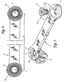
- the instrumentation comprises a pair of vertebral implants such as 1 (Figs. 4 and 5) or 2 (Figs. 6 and 7), a plate 3 (Figs. 2 and 3) providing a connection between the two implants 1 or 2, and screws 50 for fixing the plate 3 to the two implants 1 or 2.
- the plate 3 comprises opposite end portions or heads 3a which have a rounded periphery and are provided with a central aperture 5.
- heads 3a which have a rounded periphery and are provided with a central aperture 5.
- radial serrations 6 Provided around the aperture 5 and on the surface of the head 3a adapted to come to bear against the surface of the implants 1 or 2, are radial serrations 6 which extend to the periphery of the head 3, on a full circumference.
- the fixing screws 50 have rounded heads 51 connected adjacent their screw threaded portions 53, to conical portions 52 adapted to fit into corresponding conical surfaces 11 of the apertures 5.
- the bone anchorage screws 4 for spongy bone each comprise a screw threaded stem 7 extended by a conical surface of a head whose surface is flush with the surface 3b of the plate 3, when the screws 4 are placed in position through the apertures 5 and central apertures 12 of the implants 1 and 2.
- the rounded surfaces 51 of the heads of the screws 50 are flush with the surface of the plate 3 when the screws are anchored in the apertures (12, 5) of the implants 1, 2 and the end portions 3a of the plate.
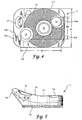
- the implant 1 is also provided with two apertures 13, 14 for receiving bone anchorage screws (not shown) on each side of the central aperture 12, and is intended especially for thoracic vertebral bodies T4 to T12.
- the apertures 13 and 14 are spaced apart a distance which is as small as possible so as to permit the fixing of the implant 1 on short vertebrae.
- the surface of the implant 1 adapted to receive the corresponding head 3a of the plate 3 has radial serrations 15 which extend completely around the aperture 12 and on each side of the apertures 13, 14.
- the serrations 15 of course match the serrations 6 so that the serrations fit together.
- the opposite surface 16 of the implant 1 has a curvature adapted to the anterior anatomy of the vertebral bodies against which the implant must be applied.
- the body of the implant 1 comprises a lateral portion 1a which extends beyond the surface occupied by the serrations 15 and in which is formed an aperture 17 adapted to cooperate with a piston.
- the aperture 14 located on the posterior side of the vertebral implant 1 is inclined in the anterior direction of the implant at an angle which is preferably about 6°, as can be seen in Fig. 4 which shows an inclined fraction 14a of the wall of the cavity 14.
- the aperture 13 of the second screw, located on the anterior side of the implant 1 has its wall perpendicular to the upper surface of the implant 1.
- the inclination of the axis of the aperture 14 toward the anterior side gives the surgeon confidence upon the insertion of the screws 4 close to the medulla canal.
- Tire fact that the aperture 13 extends in a direction perpendicular to the upper surface of the implanc 1 permits an improved bone anchorage and an increased safety against risk of wrenching away.
- the thickness e of the plate 3 varies in the same set of plates of different lengths in that the thickness of the plate 3 increases with increase in its distance 1 between the centres or axes of the apertures 5. This increase in thickness is determined in such manner as to provide a constant rigidity of the plate from the shortest plate to the longest plate of the set.
- the thickness of the plate varies progressively with the centre distance from 3 mm to 4.6 mm.
- the rigidity of the plate in this way remains constant irrespective of the distance between the implants 1 or 2, so that there is no risk of flexion of this plate after the instrumentation has been mounted on a patient.
- the yield strength of cold rolled steel 316L for forging is 1,000 MPa, steel TA6V having a yield strength of 900 MPa and titanium T40 a yield strength of 340 MPa.
- titanium T40 cannot be employed, titanium TA6V on the other hand being well suited.
- This rigidity represents the plate having 90 mm between the centres or axes.
- the thicknesses of the plates of a series of plates were defined with respect to their centre distance to obtain a constant rigidity, which resulted for the set of plates in a thickness variation ranging from 3 mm to 4.6 mm.
- the two rounded heads of the plates avoid any projecting part whatever the position of these heads relative to the implants.
- the lower face may comprise 48 serrations 6 arranged on 360° with a minimum pitch of 7° 30" and a theoretical depth of 0.9 mm.
- the serrations of a 60° triangular shape perfectly fit into the serrations of the implants. With a half-pitch offset relative to the implant it is possible to define a "0" position in which the axis of the plate 3 is perpendicular to the axis of the implant 1 or 2. In order to ovoid any projecting part, all the edges are rounded.
- the implant 2 is intended for lumbar vertebral bodies and is provided with three apertures 19, 21, 22 for receiving three corresponding anchorage screws for spongy bone (not shown).
- the walls of the apertures 19 and 21 are inclined in the anterior direction in the same way as the wall of the aperture 14, the aperture 22 being similar to the aperture 13 of the implant 1.
- the two apertures 19, 21 are located on the posterior side of the implant 2, and the aperture 22 is located on its anterior side.
- the shape of the plate 3 has been calculated by the method of finished elements. The purpose of this calculation is to optimize the shape and the section of the plate by determining the distribution of the stresses and the rigidity of the plate. Other criteria are integrated, it being necessary far the plate to adapt itself to the anatomical morphology.
- the overall shape of the implant was defined with respect to the morphology of the vertebral bodies.
- the position of the cavities receiving the spongy bone screws was defined on the basis of documents giving the heights, diameters and thicknesses of the cortical of the vertebral bodies from T4 to L4. This led to defining two implants the screw cavities of which are at different distances apart.
- Implant 1 having two apertures (Fig. 4 )
- Implant 2 having three apertures (Fig. 6)
- the maximum distances d2, d3, d5, d6 are given in the following table as a function of the minimum and maximum heights of the vertebral bodies.
- the overall height d1 may vary from 13.7 to 20 mm and the overall size d4 of the implant 2 may vary from 20 to 32 mm.
- Implant-2 apertures (1)
- Implant-3 apertures (2)
- an implant 1 having two apertures is used. If this height is between 20 and 32 mm, an implant 2 having three apertures is used.
- a minimum distance between the screws toward the interior is very important since it must be ensured that the screws are not too close together so as to avoid risk of splitting the cortical.
- the cavities (14, 19, 21) for the screws at the rear of the implant (1, 2) are inclined at 6° toward the interior for two reasons:
- the 6° were defined by the fact that it was necessary to ensure that the longest screws do not touch each other when passing through the other cortical, and that they are spaced far enough apart to avoid splitting the other cortical, which would result in an imperfect fixing of the implant.
Landscapes
- Health & Medical Sciences (AREA)
- Orthopedic Medicine & Surgery (AREA)
- Neurology (AREA)
- Life Sciences & Earth Sciences (AREA)
- Surgery (AREA)
- Molecular Biology (AREA)
- General Health & Medical Sciences (AREA)
- Biomedical Technology (AREA)
- Heart & Thoracic Surgery (AREA)
- Medical Informatics (AREA)
- Nuclear Medicine, Radiotherapy & Molecular Imaging (AREA)
- Animal Behavior & Ethology (AREA)
- Engineering & Computer Science (AREA)
- Public Health (AREA)
- Veterinary Medicine (AREA)
- Prostheses (AREA)
- Surgical Instruments (AREA)
- Orthopedics, Nursing, And Contraception (AREA)
- Eye Examination Apparatus (AREA)
- Measurement Of The Respiration, Hearing Ability, Form, And Blood Characteristics Of Living Organisms (AREA)
- Apparatus For Radiation Diagnosis (AREA)
Claims (8)
- Instrumentation für die dorso-lumbale Spinal-Osteosynthese von vorn zur Korrektur einer Kyphose auf Grund der Zerstörung eines oder zweier Wirbelkörper, wobei die Instrumentation in Kombination folgendes umfaßt:dadurch gekennzeichnet, daß die zwei Endabschnitte (3a) der Platte (3) einen abgerundeten Umfang mit einer fortlaufenden Krümmung haben, um vorstehende Teile zu vermeiden, undein Paar von Wirbelimplantaten (1,2), die erste Öffnungen (12, 13, 14; 12, 19, 21, 22) definieren,Knochenschrauben (4) zum Verankern der Implantate in zwei entsprechenden Wirbeln, die sich auf jeder Seite eines beschädigten Wirbels befinden,eine Platte (3) mit zwei Endabschnitten (3a) zur Verbindung mit den zwei Implantaten (1, 2), wobei jeder der Endabschnitte (3a) eine zweite Öffnung (5) definiert, undBefestigungsschrauben (50) zum Einsetzen durch die ersten und die zweiten Öffnungen, um die Endabschnitte (3a) an den Implantaten (1, 2) zu befestigen,
jede Befestigungsschraube (50) mit einem Kopf (51) versehen wird, der die Platte (3) berührt, wenn die Befestigungsschraube (50) in einer mittleren Öffnung (12) der ersten Öffnungen eines Implantats (1, 2) und einer zweiten Öffnung (5) des jeweiligen Endabschnitts der Platte verankert wird, wobei der Befestigungsschraubenkopf (51) abgerundet wird derart, daß eine durch den abgerundeten Kopf definierte Fläche bündig ist mit einer durch die Platte (3) definierten Fläche, wenn der Kopf (51) die Platte (3) berührt. - Instrumentation nach Anspruch 1, bei der:jedes der Implantate (1, 2) mit einem abgerundeten Abschnitt versehen wird, entsprechend dem abgerundeten Umfang der zwei Endabschnitte der Platte, unddie ersten Öffnungen (12) außerdem Knochenschraubenöffnungen (13, 14) einschließen, an diametral entgegengesetzten Orten auf dem abgerundeten Abschnitt, wobei die Knochenschraubenöffnungen konfiguriert werden, um zwei entsprechende der Knochenschrauben (4) zum Verankern der Implantate aufzunehmen.
- Instrumentation nach Anspruch 1, bei der die ersten Öffnungen (12) außerdem drei Knochenschraubenöffnungen (19, 21, 22) einschließen, um drei entsprechende der Knochenschrauben zum Verankern der Implantate aufzunehmen.
- Instrumentation nach Anspruch 1, bei der die zweiten ÖfFnungen (5) der Endabschnitte der Platte konische Kantenabschnitte (11) haben, und die Befestigungsschrauben (50) Köpfe haben, die konische Abschnitte (52) entsprechend den jeweiligen konischen Kantenabschnitten (11) der zweiten Öffnungen in den Endabschnitten der Platte definieren, wodurch ein selbsttätiges Zentrieren der Platte (3) ermöglicht wird.
- Instrumentation nach Anspruch 2, bei der:jedes der Implantate (1, 2) einen hinteren Bereich und einen entgegengesetzten vorderen Bereich einschließt, undwenigstens eine der Knochenschraubenöffnungen (13, 14) sich im hinteren Bereich befindet und eine in einer Richtung zum vorderen Bereich hin geneigte Achse hat.
- Instrumentation nach Anspruch 5, bei der jedes der Implantate eine erste Fläche hat, wobei die Neigung 6° im Verhältnis zu einer Linie senkrecht zur ersten Fläche beträgt.
- Instrumentation nach Anspruch 1, bei der jeder der zwei Endabschnitte (3a) der Platte (3) eine erste Fläche innerhalb des abgerundeten Umfangs einschließt, und ein abgerundeter Abschnitt jedes der Implantate eine zweite Fläche gegenüber der ersten Fläche einschließt, wobei jede der ersten und der zweiten Flächen mit zusammenpassenden Kerbverzahnungen (6, 15) in Radialrichtung versehen wird, verteilt um die mittlere Öffnung jedes Implantats und eine ausgerichtete ÖfFnung der zweiten Öffnungen im jeweiligen Endabschnitt der Platte für den Durchgang der Befestigungsschrauben (50).
- Instrumentation nach Anspruch 7, bei der die Kerbverzahnungen eine Mindestteilung von 7°30" haben.
Applications Claiming Priority (3)
| Application Number | Priority Date | Filing Date | Title |
|---|---|---|---|
| US08/196,517 US5487743A (en) | 1994-02-15 | 1994-02-15 | Anterior dorso-lumbar spinal osteosynthesis instrumentation for the correction of kyphosis |
| US196517 | 1994-02-15 | ||
| PCT/US1995/002019 WO1995021579A1 (en) | 1994-02-15 | 1995-02-15 | Anterior dorso-lumbar spinal osteosynthesis instrumentation for the correction of kyphosis |
Publications (3)
| Publication Number | Publication Date |
|---|---|
| EP0744924A1 EP0744924A1 (de) | 1996-12-04 |
| EP0744924A4 EP0744924A4 (de) | 1998-08-05 |
| EP0744924B1 true EP0744924B1 (de) | 2003-06-04 |
Family
ID=22725736
Family Applications (1)
| Application Number | Title | Priority Date | Filing Date |
|---|---|---|---|
| EP95910292A Expired - Lifetime EP0744924B1 (de) | 1994-02-15 | 1995-02-15 | Für die dorsale, lumare wirbelsäulenosteosynthese geeignetes instrumentarium zur korrektur einer kyphose von vorn |
Country Status (8)
| Country | Link |
|---|---|
| US (2) | US5487743A (de) |
| EP (1) | EP0744924B1 (de) |
| JP (1) | JPH09508835A (de) |
| AT (1) | ATE241935T1 (de) |
| AU (1) | AU1846295A (de) |
| DE (1) | DE69530972T2 (de) |
| ES (1) | ES2201098T3 (de) |
| WO (1) | WO1995021579A1 (de) |
Families Citing this family (116)
| Publication number | Priority date | Publication date | Assignee | Title |
|---|---|---|---|---|
| US6001099A (en) * | 1998-06-08 | 1999-12-14 | Huebner; Randall J. | Bone plate with varying rigidity |
| US5634925A (en) * | 1993-02-19 | 1997-06-03 | Alphatec Manufacturing, Inc. | Apparatus and method for spinal fixation system |
| EP0699056B1 (de) * | 1993-05-18 | 1997-01-29 | Schäfer micomed GmbH | Knochenchirurgische haltevorrichtung |
| ES2125805B1 (es) * | 1996-09-18 | 1999-11-16 | Prim S A | Marco de hiperextension dorsolumbar. |
| US5871548A (en) * | 1996-12-07 | 1999-02-16 | Johnson & Johnson Professional, Inc. | Modular acetabular reinforcement system |
| JP4467647B2 (ja) * | 1997-02-11 | 2010-05-26 | ウォーソー・オーソペディック・インコーポレーテッド | 骨プレーティングシステム |
| ATE309752T1 (de) * | 1997-02-11 | 2005-12-15 | Michelson Gary K | System für die vorder-verplattung der halswirbelsäule |
| FR2771917B1 (fr) * | 1997-12-04 | 2000-05-05 | Dimso Sa | Dispositif de blocage pour une instrumentation rachidienne |
| US6482233B1 (en) | 1998-01-29 | 2002-11-19 | Synthes(U.S.A.) | Prosthetic interbody spacer |
| US6325803B1 (en) | 1998-02-18 | 2001-12-04 | Walter Lorenz Surgical, Inc. | Method and apparatus for mandibular osteosynthesis |
| US7052499B2 (en) * | 1998-02-18 | 2006-05-30 | Walter Lorenz Surgical, Inc. | Method and apparatus for bone fracture fixation |
| US6129728A (en) * | 1998-02-18 | 2000-10-10 | Walter Lorenz Surgical, Inc. | Method and apparatus for mandibular osteosynthesis |
| FR2778088B1 (fr) * | 1998-04-30 | 2000-09-08 | Materiel Orthopedique En Abreg | Implant anterieur notamment pour le rachis cervical |
| US20040220571A1 (en) * | 1998-04-30 | 2004-11-04 | Richard Assaker | Bone plate assembly |
| US6533786B1 (en) * | 1999-10-13 | 2003-03-18 | Sdgi Holdings, Inc. | Anterior cervical plating system |
| US6146386A (en) * | 1999-02-04 | 2000-11-14 | Sdgi Holdings, Inc. | Cable operated bone anchor compressor |
| US6416553B1 (en) | 1999-03-31 | 2002-07-09 | Biomet, Inc. | Method and apparatus for providing a modular acetabular prosthesis |
| WO2000064359A1 (en) * | 1999-04-28 | 2000-11-02 | Harrington James Frederick Jr | Modular anterior cervical plate |
| US6224602B1 (en) * | 1999-10-11 | 2001-05-01 | Interpore Cross International | Bone stabilization plate with a secured-locking mechanism for cervical fixation |
| US6692503B2 (en) * | 1999-10-13 | 2004-02-17 | Sdgi Holdings, Inc | System and method for securing a plate to the spinal column |
| US6530929B1 (en) * | 1999-10-20 | 2003-03-11 | Sdgi Holdings, Inc. | Instruments for stabilization of bony structures |
| US6875212B2 (en) * | 2000-06-23 | 2005-04-05 | Vertelink Corporation | Curable media for implantable medical device |
| US6749614B2 (en) | 2000-06-23 | 2004-06-15 | Vertelink Corporation | Formable orthopedic fixation system with cross linking |
| US6899713B2 (en) * | 2000-06-23 | 2005-05-31 | Vertelink Corporation | Formable orthopedic fixation system |
| US6821277B2 (en) | 2000-06-23 | 2004-11-23 | University Of Southern California Patent And Copyright Administration | Percutaneous vertebral fusion system |
| US6964667B2 (en) * | 2000-06-23 | 2005-11-15 | Sdgi Holdings, Inc. | Formed in place fixation system with thermal acceleration |
| AU2000252043B2 (en) * | 2000-06-26 | 2004-10-21 | Synthes Gmbh | Bone plate for osteosynthesis |
| US6524315B1 (en) | 2000-08-08 | 2003-02-25 | Depuy Acromed, Inc. | Orthopaedic rod/plate locking mechanism |
| US20070055249A1 (en) * | 2003-06-20 | 2007-03-08 | Jensen David G | Bone plates with intraoperatively tapped apertures |
| US7153309B2 (en) * | 2002-11-19 | 2006-12-26 | Acumed Llc | Guide system for bone-repair devices |
| US7578825B2 (en) * | 2004-04-19 | 2009-08-25 | Acumed Llc | Placement of fasteners into bone |
| US20050240187A1 (en) * | 2004-04-22 | 2005-10-27 | Huebner Randall J | Expanded fixation of bones |
| US20050234458A1 (en) * | 2004-04-19 | 2005-10-20 | Huebner Randall J | Expanded stabilization of bones |
| US7717945B2 (en) * | 2002-07-22 | 2010-05-18 | Acumed Llc | Orthopedic systems |
| US7537604B2 (en) | 2002-11-19 | 2009-05-26 | Acumed Llc | Bone plates with slots |
| US7862587B2 (en) | 2004-02-27 | 2011-01-04 | Jackson Roger P | Dynamic stabilization assemblies, tool set and method |
| US20050065521A1 (en) * | 2002-02-22 | 2005-03-24 | Steger Shon D. | Method and apparatus for bone fracture fixation |
| US6660006B2 (en) * | 2002-04-17 | 2003-12-09 | Stryker Spine | Rod persuader |
| US20040116930A1 (en) * | 2002-06-10 | 2004-06-17 | O'driscoll Shawn W. | Bone plates |
| EP1542602B1 (de) | 2002-07-22 | 2010-11-17 | Acumed LLC | Knochenfusionssystem |
| US7189244B2 (en) * | 2002-08-02 | 2007-03-13 | Depuy Spine, Inc. | Compressor for use in minimally invasive surgery |
| KR101081269B1 (ko) | 2002-11-19 | 2011-11-08 | 어큠드 엘엘씨 | 조정가능한 본 플레이트 |
| KR20050083916A (ko) | 2002-11-19 | 2005-08-26 | 어큠드 엘엘씨 | 변형가능한 뼈 평판 |
| US7094238B2 (en) | 2002-11-22 | 2006-08-22 | Sdgi Holdings, Inc. | Variable angle adaptive plate |
| US20050055096A1 (en) * | 2002-12-31 | 2005-03-10 | Depuy Spine, Inc. | Functional spinal unit prosthetic |
| US7101398B2 (en) * | 2002-12-31 | 2006-09-05 | Depuy Acromed, Inc. | Prosthetic facet joint ligament |
| US20040162558A1 (en) * | 2003-02-18 | 2004-08-19 | Hegde Sajan K. | Spinal plate having an integral rod connector portion |
| EP1470803A1 (de) * | 2003-04-23 | 2004-10-27 | Sepitec Foundation | Vorrichtung für die Spondylodese |
| US7473267B2 (en) * | 2003-04-25 | 2009-01-06 | Warsaw Orthopedic, Inc. | System and method for minimally invasive posterior fixation |
| US20050131413A1 (en) * | 2003-06-20 | 2005-06-16 | O'driscoll Shawn W. | Bone plate with interference fit screw |
| CN100553577C (zh) * | 2003-06-20 | 2009-10-28 | 精密医疗责任有限公司 | 用于在手术中对接骨板攻螺纹的系统 |
| US7635365B2 (en) | 2003-08-28 | 2009-12-22 | Ellis Thomas J | Bone plates |
| US7455685B2 (en) * | 2003-09-29 | 2008-11-25 | Warsaw Orthopedic, Inc. | Instruments and methods for securing a connecting element along a bony segment |
| US8105367B2 (en) * | 2003-09-29 | 2012-01-31 | Smith & Nephew, Inc. | Bone plate and bone plate assemblies including polyaxial fasteners |
| WO2007014192A2 (en) | 2005-07-25 | 2007-02-01 | Smith & Nephew, Inc. | Systems and methods for using polyaxial plates |
| US7179261B2 (en) | 2003-12-16 | 2007-02-20 | Depuy Spine, Inc. | Percutaneous access devices and bone anchor assemblies |
| US11419642B2 (en) | 2003-12-16 | 2022-08-23 | Medos International Sarl | Percutaneous access devices and bone anchor assemblies |
| WO2005074580A2 (en) * | 2004-02-02 | 2005-08-18 | Acumed Llc | Bone plate with toothed aperture |
| US7611517B2 (en) | 2004-02-27 | 2009-11-03 | Warsaw Orthopedic, Inc. | Rod reducer |
| US7160300B2 (en) | 2004-02-27 | 2007-01-09 | Jackson Roger P | Orthopedic implant rod reduction tool set and method |
| WO2005092218A1 (en) | 2004-02-27 | 2005-10-06 | Jackson Roger P | Orthopedic implant rod reduction tool set and method |
| US7686814B2 (en) * | 2004-07-06 | 2010-03-30 | Warsaw Orthopedic, Inc. | Systems and methods for compressing and distracting vertebrae of the spinal column |
| US7465306B2 (en) | 2004-08-13 | 2008-12-16 | Warsaw Orthopedic, Inc. | System and method for positioning a connecting member adjacent the spinal column in minimally invasive procedures |
| US20060106387A1 (en) * | 2004-11-16 | 2006-05-18 | Depuy Spine, Inc. | Spinal plate system and method of use |
| US7771433B2 (en) * | 2004-12-14 | 2010-08-10 | Depuy Products, Inc. | Bone fracture fixation plate shaping system |
| US8172886B2 (en) | 2004-12-14 | 2012-05-08 | Depuy Products, Inc. | Bone plate with pre-assembled drill guide tips |
| US20060155283A1 (en) * | 2005-01-07 | 2006-07-13 | Depuy Spine Sarl | Occipital plate and guide systems |
| ES2318917B1 (es) * | 2005-03-30 | 2010-02-04 | Sdgi Holdings Inc. | Sistema para la correccion tridimensional de la curvatura de la columna vertebral en problemas de escoliosis por alineacion coplanar de los tornillos pediculares. |
| US7491208B2 (en) | 2005-04-28 | 2009-02-17 | Warsaw Orthopedic, Inc. | Instrument and method for guiding surgical implants and instruments during surgery |
| US7871424B2 (en) * | 2005-05-23 | 2011-01-18 | Custom Spine, Inc. | Spinal rod inserter |
| US7628800B2 (en) * | 2005-06-03 | 2009-12-08 | Warsaw Orthopedic, Inc. | Formed in place corpectomy device |
| US7727239B2 (en) * | 2005-06-10 | 2010-06-01 | Zimmer Technology, Inc. | Milling system with guide paths and related methods for resecting a joint articulation surface |
| US8177823B2 (en) * | 2005-06-30 | 2012-05-15 | Depuy Spine Sarl | Orthopedic clamping hook assembly |
| US8382807B2 (en) | 2005-07-25 | 2013-02-26 | Smith & Nephew, Inc. | Systems and methods for using polyaxial plates |
| US7695475B2 (en) * | 2005-08-26 | 2010-04-13 | Warsaw Orthopedic, Inc. | Instruments for minimally invasive stabilization of bony structures |
| US7935126B2 (en) * | 2006-03-20 | 2011-05-03 | Depuy Products, Inc. | Bone plate shaping system |
| US7740634B2 (en) * | 2006-03-20 | 2010-06-22 | Depuy Products, Inc. | Method of bone plate shaping |
| WO2008039447A1 (en) | 2006-09-25 | 2008-04-03 | Stryker Spine | Percutaneous compression and distraction system |
| US8480718B2 (en) * | 2006-12-21 | 2013-07-09 | Warsaw Orthopedic, Inc. | Curable orthopedic implant devices configured to be hardened after placement in vivo |
| US7771476B2 (en) | 2006-12-21 | 2010-08-10 | Warsaw Orthopedic Inc. | Curable orthopedic implant devices configured to harden after placement in vivo by application of a cure-initiating energy before insertion |
| US8663328B2 (en) * | 2006-12-21 | 2014-03-04 | Warsaw Orthopedic, Inc. | Methods for positioning a load-bearing component of an orthopedic implant device by inserting a malleable device that hardens in vivo |
| US8758407B2 (en) * | 2006-12-21 | 2014-06-24 | Warsaw Orthopedic, Inc. | Methods for positioning a load-bearing orthopedic implant device in vivo |
| US20080249531A1 (en) * | 2007-02-27 | 2008-10-09 | Warsaw Orthopedic, Inc. | Instruments and methods for minimally invasive insertion of dynamic implants |
| US20080269805A1 (en) | 2007-04-25 | 2008-10-30 | Warsaw Orthopedic, Inc. | Methods for correcting spinal deformities |
| GB2450247B (en) * | 2007-06-15 | 2010-01-13 | Joel Gillard | Rib fixation with an intramedullary nail |
| US20090088803A1 (en) * | 2007-10-01 | 2009-04-02 | Warsaw Orthopedic, Inc. | Flexible members for correcting spinal deformities |
| US8267957B1 (en) * | 2007-12-14 | 2012-09-18 | Holmed Corporation | Compressor with extended ratchet bar feature |
| US8202299B2 (en) | 2008-03-19 | 2012-06-19 | Collabcom II, LLC | Interspinous implant, tools and methods of implanting |
| US8414584B2 (en) | 2008-07-09 | 2013-04-09 | Icon Orthopaedic Concepts, Llc | Ankle arthrodesis nail and outrigger assembly |
| EP2339976B1 (de) | 2008-07-09 | 2016-03-16 | Icon Orthopaedic Concepts, LLC | Fussgelenks-arthrodesenagel und auslegeranordnung |
| US8287546B2 (en) * | 2008-07-31 | 2012-10-16 | Zimmer Spine, Inc. | Surgical instrument with integrated compression and distraction mechanisms |
| US9237910B2 (en) | 2012-01-26 | 2016-01-19 | Acute Innovations Llc | Clip for rib stabilization |
| US12285197B2 (en) | 2008-10-10 | 2025-04-29 | Acumed Llc | Bone fixation system with opposed mounting portions |
| KR20120082397A (ko) * | 2009-07-24 | 2012-07-23 | 스파이널 유에스에이 엘엘씨 | 골 플레이트 시스템 및 골 플레이트 시스템의 이용 방법 |
| KR20120082396A (ko) | 2009-07-24 | 2012-07-23 | 스파이널 유에스에이 엘엘씨 | 골 플레이트 나사 차단 시스템 및 방법 |
| US8568417B2 (en) | 2009-12-18 | 2013-10-29 | Charles River Engineering Solutions And Technologies, Llc | Articulating tool and methods of using |
| FR2954689B1 (fr) * | 2009-12-28 | 2012-12-21 | Sterispine | Dispositif et methode pour la chirurgie rachidienne. |
| CN102883672A (zh) * | 2010-03-03 | 2013-01-16 | 兰克斯股份有限公司 | 骨板系统和方法 |
| FR2956971B1 (fr) * | 2010-03-08 | 2012-03-02 | Memometal Technologies | Systeme d'osteosynthese a plaque |
| FR2956972B1 (fr) * | 2010-03-08 | 2012-12-28 | Memometal Technologies | Plaque d'osteosynthese articulee |
| CN102293680B (zh) | 2010-06-24 | 2014-04-16 | 华沙整形外科股份有限公司 | 共面变形矫正系统 |
| US8920471B2 (en) | 2010-07-12 | 2014-12-30 | K2M, Inc. | Transverse connector |
| RU2013158111A (ru) | 2011-06-15 | 2015-07-20 | Смит Энд Нефью, Инк. | Имплантат с переменным углом фиксации |
| JP6240076B2 (ja) | 2011-09-30 | 2017-11-29 | アキュート・イノヴェーションズ・エルエルシー | 対向する取付け部分を備えた骨固定システム |
| US9125703B2 (en) | 2012-01-16 | 2015-09-08 | K2M, Inc. | Rod reducer, compressor, distractor system |
| US20130338714A1 (en) | 2012-06-15 | 2013-12-19 | Arvin Chang | Magnetic implants with improved anatomical compatibility |
| US9254158B2 (en) | 2012-10-04 | 2016-02-09 | DePuy Synthes Products, Inc. | Orthognathic bending pliers |
| BR112015007464B1 (pt) * | 2012-10-04 | 2021-03-23 | Synthes Gmbh | Ferramenta dobradora |
| US9408716B1 (en) | 2013-12-06 | 2016-08-09 | Stryker European Holdings I, Llc | Percutaneous posterior spinal fusion implant construction and method |
| US10159579B1 (en) | 2013-12-06 | 2018-12-25 | Stryker European Holdings I, Llc | Tubular instruments for percutaneous posterior spinal fusion systems and methods |
| US9744050B1 (en) | 2013-12-06 | 2017-08-29 | Stryker European Holdings I, Llc | Compression and distraction system for percutaneous posterior spinal fusion |
| CA2992336C (en) | 2013-12-13 | 2020-04-14 | Stryker European Holdings I, Llc | Tissue retraction and vertebral displacement devices, systems, and methods for posterior spinal fusion |
| JP6594946B2 (ja) | 2014-07-03 | 2019-10-23 | アキュームド・エルエルシー | 移動可能な継手を備える骨プレート |
| US10363145B2 (en) * | 2015-02-23 | 2019-07-30 | Amendia, Inc. | Lateral plate and spinal implant system and method |
| US10993750B2 (en) | 2015-09-18 | 2021-05-04 | Smith & Nephew, Inc. | Bone plate |
| US20230032049A1 (en) * | 2021-07-29 | 2023-02-02 | David Skaggs | Systems and methods for treatment of spinal deformities |
Family Cites Families (4)
| Publication number | Priority date | Publication date | Assignee | Title |
|---|---|---|---|---|
| DE3121271A1 (de) * | 1981-05-29 | 1982-12-23 | Max Bernhard 7900 Ulm Ulrich | Distraktionsgeraet zur korrektur insbesondere kyphotischer wirbelsaeulenbereiche |
| DE8513288U1 (de) * | 1985-05-06 | 1986-09-04 | Wolter, Dietmar, Prof. Dr., 2000 Hamburg | Osteosyntheseplatte |
| FR2651992B1 (fr) * | 1989-09-18 | 1991-12-13 | Sofamor | Implant pour osteosynthese rachidienne dorso-lombaire anterieure destine a la correction de cyphoses. |
| US5127912A (en) * | 1990-10-05 | 1992-07-07 | R. Charles Ray | Sacral implant system |
-
1994
- 1994-02-15 US US08/196,517 patent/US5487743A/en not_active Expired - Lifetime
-
1995
- 1995-02-15 JP JP7521435A patent/JPH09508835A/ja active Pending
- 1995-02-15 WO PCT/US1995/002019 patent/WO1995021579A1/en not_active Ceased
- 1995-02-15 AU AU18462/95A patent/AU1846295A/en not_active Abandoned
- 1995-02-15 EP EP95910292A patent/EP0744924B1/de not_active Expired - Lifetime
- 1995-02-15 AT AT95910292T patent/ATE241935T1/de not_active IP Right Cessation
- 1995-02-15 DE DE69530972T patent/DE69530972T2/de not_active Expired - Fee Related
- 1995-02-15 ES ES95910292T patent/ES2201098T3/es not_active Expired - Lifetime
- 1995-05-26 US US08/452,645 patent/US5591167A/en not_active Expired - Fee Related
Also Published As
| Publication number | Publication date |
|---|---|
| ATE241935T1 (de) | 2003-06-15 |
| US5591167A (en) | 1997-01-07 |
| DE69530972T2 (de) | 2004-04-22 |
| DE69530972D1 (de) | 2003-07-10 |
| US5487743A (en) | 1996-01-30 |
| AU1846295A (en) | 1995-08-29 |
| EP0744924A1 (de) | 1996-12-04 |
| WO1995021579A1 (en) | 1995-08-17 |
| ES2201098T3 (es) | 2004-03-16 |
| EP0744924A4 (de) | 1998-08-05 |
| JPH09508835A (ja) | 1997-09-09 |
Similar Documents
| Publication | Publication Date | Title |
|---|---|---|
| US5487743A (en) | Anterior dorso-lumbar spinal osteosynthesis instrumentation for the correction of kyphosis | |
| US10888358B2 (en) | Bone plate system | |
| US6136002A (en) | Anterior spinal fixation system | |
| US5603714A (en) | Instrument for anterior correction of scoliosis or the like | |
| US6635087B2 (en) | Laminoplasty implants and methods of use | |
| EP0253796B1 (de) | Anatomische Knochenplatte bzw. Fixationsplatte | |
| US6589243B1 (en) | Posterior backbone osteosynthesis device | |
| US6136003A (en) | Device for linking adjacent rods in spinal instrumentation | |
| US8486117B2 (en) | Multi-axial bone plate system | |
| US8216312B2 (en) | Spinal interbody system and method | |
| US6565571B1 (en) | Anterior osteosynthesis plate for lumbar vertebrae or sacral lumbar vertebra and instrument for positioning same | |
| US5951553A (en) | Methods and apparatus for fusionless treatment of spinal deformities | |
| US10507050B2 (en) | Plate for osteosynthesis | |
| US20040210222A1 (en) | Laminoplasty plates and methods of use | |
| US20030045875A1 (en) | Spinal assembly plate | |
| JPH08206143A (ja) | ボーンプレートとボーンスクリュー | |
| EP0812156A1 (de) | Einsatz zur befestigung von knochenschrauben an knochenplatten | |
| EP3917457B1 (de) | Glenoidimplantat | |
| US20050010214A1 (en) | System of holding at least two vertebrae together for the purpose of spinal osteosynthesis | |
| US12185997B2 (en) | Pedicle fixation system | |
| US11744619B2 (en) | Faceted bone plate | |
| US20190388127A1 (en) | Interpedicular Spacer |
Legal Events
| Date | Code | Title | Description |
|---|---|---|---|
| PUAI | Public reference made under article 153(3) epc to a published international application that has entered the european phase |
Free format text: ORIGINAL CODE: 0009012 |
|
| 17P | Request for examination filed |
Effective date: 19960812 |
|
| AK | Designated contracting states |
Kind code of ref document: A1 Designated state(s): AT BE CH DE DK ES FR GB GR IE IT LI LU MC NL PT SE |
|
| A4 | Supplementary search report drawn up and despatched |
Effective date: 19980618 |
|
| AK | Designated contracting states |
Kind code of ref document: A4 Designated state(s): AT BE CH DE DK ES FR GB GR IE IT LI LU MC NL PT SE |
|
| 17Q | First examination report despatched |
Effective date: 20001130 |
|
| GRAG | Despatch of communication of intention to grant |
Free format text: ORIGINAL CODE: EPIDOS AGRA |
|
| GRAG | Despatch of communication of intention to grant |
Free format text: ORIGINAL CODE: EPIDOS AGRA |
|
| GRAH | Despatch of communication of intention to grant a patent |
Free format text: ORIGINAL CODE: EPIDOS IGRA |
|
| GRAH | Despatch of communication of intention to grant a patent |
Free format text: ORIGINAL CODE: EPIDOS IGRA |
|
| GRAA | (expected) grant |
Free format text: ORIGINAL CODE: 0009210 |
|
| AK | Designated contracting states |
Designated state(s): AT BE CH DE DK ES FR GB GR IE IT LI LU MC NL PT SE |
|
| PG25 | Lapsed in a contracting state [announced via postgrant information from national office to epo] |
Ref country code: NL Free format text: LAPSE BECAUSE OF FAILURE TO SUBMIT A TRANSLATION OF THE DESCRIPTION OR TO PAY THE FEE WITHIN THE PRESCRIBED TIME-LIMIT Effective date: 20030604 Ref country code: LI Free format text: LAPSE BECAUSE OF FAILURE TO SUBMIT A TRANSLATION OF THE DESCRIPTION OR TO PAY THE FEE WITHIN THE PRESCRIBED TIME-LIMIT Effective date: 20030604 Ref country code: FR Free format text: LAPSE BECAUSE OF FAILURE TO SUBMIT A TRANSLATION OF THE DESCRIPTION OR TO PAY THE FEE WITHIN THE PRESCRIBED TIME-LIMIT Effective date: 20030604 Ref country code: CH Free format text: LAPSE BECAUSE OF FAILURE TO SUBMIT A TRANSLATION OF THE DESCRIPTION OR TO PAY THE FEE WITHIN THE PRESCRIBED TIME-LIMIT Effective date: 20030604 |
|
| REG | Reference to a national code |
Ref country code: GB Ref legal event code: FG4D |
|
| REG | Reference to a national code |
Ref country code: CH Ref legal event code: EP |
|
| REG | Reference to a national code |
Ref country code: IE Ref legal event code: FG4D |
|
| REF | Corresponds to: |
Ref document number: 69530972 Country of ref document: DE Date of ref document: 20030710 Kind code of ref document: P |
|
| PG25 | Lapsed in a contracting state [announced via postgrant information from national office to epo] |
Ref country code: SE Free format text: LAPSE BECAUSE OF FAILURE TO SUBMIT A TRANSLATION OF THE DESCRIPTION OR TO PAY THE FEE WITHIN THE PRESCRIBED TIME-LIMIT Effective date: 20030904 Ref country code: PT Free format text: LAPSE BECAUSE OF FAILURE TO SUBMIT A TRANSLATION OF THE DESCRIPTION OR TO PAY THE FEE WITHIN THE PRESCRIBED TIME-LIMIT Effective date: 20030904 Ref country code: GR Free format text: LAPSE BECAUSE OF FAILURE TO SUBMIT A TRANSLATION OF THE DESCRIPTION OR TO PAY THE FEE WITHIN THE PRESCRIBED TIME-LIMIT Effective date: 20030904 Ref country code: DK Free format text: LAPSE BECAUSE OF FAILURE TO SUBMIT A TRANSLATION OF THE DESCRIPTION OR TO PAY THE FEE WITHIN THE PRESCRIBED TIME-LIMIT Effective date: 20030904 |
|
| NLV1 | Nl: lapsed or annulled due to failure to fulfill the requirements of art. 29p and 29m of the patents act | ||
| REG | Reference to a national code |
Ref country code: CH Ref legal event code: PL |
|
| PG25 | Lapsed in a contracting state [announced via postgrant information from national office to epo] |
Ref country code: LU Free format text: LAPSE BECAUSE OF NON-PAYMENT OF DUE FEES Effective date: 20040215 |
|
| PG25 | Lapsed in a contracting state [announced via postgrant information from national office to epo] |
Ref country code: IE Free format text: LAPSE BECAUSE OF NON-PAYMENT OF DUE FEES Effective date: 20040216 |
|
| PG25 | Lapsed in a contracting state [announced via postgrant information from national office to epo] |
Ref country code: MC Free format text: LAPSE BECAUSE OF NON-PAYMENT OF DUE FEES Effective date: 20040228 |
|
| REG | Reference to a national code |
Ref country code: ES Ref legal event code: FG2A Ref document number: 2201098 Country of ref document: ES Kind code of ref document: T3 |
|
| PLBE | No opposition filed within time limit |
Free format text: ORIGINAL CODE: 0009261 |
|
| STAA | Information on the status of an ep patent application or granted ep patent |
Free format text: STATUS: NO OPPOSITION FILED WITHIN TIME LIMIT |
|
| 26N | No opposition filed |
Effective date: 20040305 |
|
| EN | Fr: translation not filed | ||
| REG | Reference to a national code |
Ref country code: IE Ref legal event code: MM4A |
|
| PGFP | Annual fee paid to national office [announced via postgrant information from national office to epo] |
Ref country code: ES Payment date: 20080214 Year of fee payment: 14 |
|
| PGFP | Annual fee paid to national office [announced via postgrant information from national office to epo] |
Ref country code: GB Payment date: 20080108 Year of fee payment: 14 Ref country code: DE Payment date: 20080229 Year of fee payment: 14 Ref country code: IT Payment date: 20080220 Year of fee payment: 14 |
|
| PGFP | Annual fee paid to national office [announced via postgrant information from national office to epo] |
Ref country code: AT Payment date: 20080109 Year of fee payment: 14 |
|
| PGFP | Annual fee paid to national office [announced via postgrant information from national office to epo] |
Ref country code: BE Payment date: 20080228 Year of fee payment: 14 |
|
| BERE | Be: lapsed |
Owner name: *SOFAMOR S.N.C. Effective date: 20090228 |
|
| GBPC | Gb: european patent ceased through non-payment of renewal fee |
Effective date: 20090215 |
|
| PG25 | Lapsed in a contracting state [announced via postgrant information from national office to epo] |
Ref country code: AT Free format text: LAPSE BECAUSE OF NON-PAYMENT OF DUE FEES Effective date: 20090215 |
|
| PG25 | Lapsed in a contracting state [announced via postgrant information from national office to epo] |
Ref country code: DE Free format text: LAPSE BECAUSE OF NON-PAYMENT OF DUE FEES Effective date: 20090901 |
|
| PG25 | Lapsed in a contracting state [announced via postgrant information from national office to epo] |
Ref country code: BE Free format text: LAPSE BECAUSE OF NON-PAYMENT OF DUE FEES Effective date: 20090228 |
|
| REG | Reference to a national code |
Ref country code: ES Ref legal event code: FD2A Effective date: 20090216 |
|
| PG25 | Lapsed in a contracting state [announced via postgrant information from national office to epo] |
Ref country code: GB Free format text: LAPSE BECAUSE OF NON-PAYMENT OF DUE FEES Effective date: 20090215 |
|
| PG25 | Lapsed in a contracting state [announced via postgrant information from national office to epo] |
Ref country code: ES Free format text: LAPSE BECAUSE OF NON-PAYMENT OF DUE FEES Effective date: 20090216 |
|
| PG25 | Lapsed in a contracting state [announced via postgrant information from national office to epo] |
Ref country code: IT Free format text: LAPSE BECAUSE OF NON-PAYMENT OF DUE FEES Effective date: 20090215 |