EP0745511A2 - Dispositif d'éclairage pour véhicule - Google Patents
Dispositif d'éclairage pour véhicule Download PDFInfo
- Publication number
- EP0745511A2 EP0745511A2 EP96107643A EP96107643A EP0745511A2 EP 0745511 A2 EP0745511 A2 EP 0745511A2 EP 96107643 A EP96107643 A EP 96107643A EP 96107643 A EP96107643 A EP 96107643A EP 0745511 A2 EP0745511 A2 EP 0745511A2
- Authority
- EP
- European Patent Office
- Prior art keywords
- housing part
- vehicle
- recess
- lighting device
- reflector
- Prior art date
- Legal status (The legal status is an assumption and is not a legal conclusion. Google has not performed a legal analysis and makes no representation as to the accuracy of the status listed.)
- Granted
Links
Images
Classifications
-
- B—PERFORMING OPERATIONS; TRANSPORTING
- B60—VEHICLES IN GENERAL
- B60Q—ARRANGEMENT OF SIGNALLING OR LIGHTING DEVICES, THE MOUNTING OR SUPPORTING THEREOF OR CIRCUITS THEREFOR, FOR VEHICLES IN GENERAL
- B60Q1/00—Arrangement of optical signalling or lighting devices, the mounting or supporting thereof or circuits therefor
- B60Q1/02—Arrangement of optical signalling or lighting devices, the mounting or supporting thereof or circuits therefor the devices being primarily intended to illuminate the way ahead or to illuminate other areas of way or environments
- B60Q1/04—Arrangement of optical signalling or lighting devices, the mounting or supporting thereof or circuits therefor the devices being primarily intended to illuminate the way ahead or to illuminate other areas of way or environments the devices being headlights
- B60Q1/06—Arrangement of optical signalling or lighting devices, the mounting or supporting thereof or circuits therefor the devices being primarily intended to illuminate the way ahead or to illuminate other areas of way or environments the devices being headlights adjustable, e.g. remotely-controlled from inside vehicle
- B60Q1/068—Arrangement of optical signalling or lighting devices, the mounting or supporting thereof or circuits therefor the devices being primarily intended to illuminate the way ahead or to illuminate other areas of way or environments the devices being headlights adjustable, e.g. remotely-controlled from inside vehicle by mechanical means
- B60Q1/0683—Adjustable by rotation of a screw
-
- B—PERFORMING OPERATIONS; TRANSPORTING
- B60—VEHICLES IN GENERAL
- B60Q—ARRANGEMENT OF SIGNALLING OR LIGHTING DEVICES, THE MOUNTING OR SUPPORTING THEREOF OR CIRCUITS THEREFOR, FOR VEHICLES IN GENERAL
- B60Q1/00—Arrangement of optical signalling or lighting devices, the mounting or supporting thereof or circuits therefor
- B60Q1/02—Arrangement of optical signalling or lighting devices, the mounting or supporting thereof or circuits therefor the devices being primarily intended to illuminate the way ahead or to illuminate other areas of way or environments
- B60Q1/04—Arrangement of optical signalling or lighting devices, the mounting or supporting thereof or circuits therefor the devices being primarily intended to illuminate the way ahead or to illuminate other areas of way or environments the devices being headlights
- B60Q1/0408—Arrangement of optical signalling or lighting devices, the mounting or supporting thereof or circuits therefor the devices being primarily intended to illuminate the way ahead or to illuminate other areas of way or environments the devices being headlights built into the vehicle body, e.g. details concerning the mounting of the headlamps on the vehicle body
- B60Q1/0466—Arrangement of optical signalling or lighting devices, the mounting or supporting thereof or circuits therefor the devices being primarily intended to illuminate the way ahead or to illuminate other areas of way or environments the devices being headlights built into the vehicle body, e.g. details concerning the mounting of the headlamps on the vehicle body with arrangement for sealing the headlamp with respect to the vehicle body, or for concealling gaps between the headlamp and the vehicle body
Definitions
- the invention relates to a lighting device for vehicles according to the preamble of claim 1.
- Such a lighting device is known from DE 30 30 427 A1.
- This lighting device is designed as a headlight and has a housing part at least partially surrounded by at least one reflector and at least one light source.
- the housing part has a light exit opening at its front end, which is closed with a translucent cover plate.
- the housing part can be fastened to a front part of the vehicle and has a rear wall opposite the cover plate with an opening which can be closed with a separate closure part.
- a closed interior is delimited by the housing part, the closure part and the cover plate, in which the reflector and the light source are arranged and thus protected against dirt and moisture.
- the housing part with the closure part requires one large use of fabric for its manufacture and a large installation space on the vehicle, which should be avoided.
- the lighting device according to the invention for vehicles with the features of claim 1 has the advantage that a small amount of material is required for the housing part, since this need not have its own rear wall. In this case, even with manufacturing tolerances of the housing part and / or of the vehicle part having the recess, a secure seal of the interior is achieved, manufacturing tolerances in the insertion direction of the housing part being compensated for by the displaceability of the housing part in the recess and manufacturing tolerances transverse to the insertion direction of the housing part by the elastically deformable sealing element be balanced.
- the sealing element can compensate for relatively large manufacturing tolerances transversely to the direction of insertion of the housing part with secure sealing of the interior.
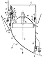
- FIG. 1 An embodiment of the invention is shown in the drawing and explained in more detail in the following description.
- the figure shows a lighting device arranged on a vehicle part in a vertical longitudinal section.
- a vehicle in particular a motor vehicle, shows a front vehicle part 10 in the figure, which can be part of the body of the vehicle or a carrier and can consist of metal, for example cast metal or sheet metal, or plastic.
- the vehicle part 10 has at least one cup-shaped depression 14 arranged in the direction of travel 12 of the vehicle and opposite to the direction of travel 12.
- the recess 14 is formed closed on its side walls and on its bottom.
- a depression 14 is usually formed on the two lateral edge regions of the vehicle part 10.
- the depression 14 can be designed such that its clear width widens toward its front edge pointing in the direction of travel 12, for example conically.
- a front part 16 for the vehicle can be fastened to the vehicle part 10, which is pushed towards the vehicle part 10 against the direction of travel 12 and can be fastened to the vehicle part 10 by means of fastening elements (not shown).
- At least one lighting device 18 is attached to the front part 16, for example in the form of a headlight. Further parts and units of the vehicle can also be attached to the front part 16.
- a headlight 18 is usually attached in each of the two lateral edge regions of the front part 16.
- the headlight 18 has a frame-like housing part 20 which has a light exit opening 22 at its front end pointing in the direction of travel 12, which is closed with a translucent cover plate 24 made of glass or plastic.
- the housing part 20 can be round, rectangular or with any other shape in cross section.
- the housing part 20 is preferably made of plastic, but can also consist of other suitable material, for example sheet metal or cast metal.
- the cover plate 24 can be smooth or have optically active elements through which light passing through is deflected.
- the cover plate 24 is fastened with a peripheral edge at the front end of the housing part 20, for example glued, or by means of one or more retaining clips or by a snap connection.
- At least one reflector 26 is mounted on the housing part 20 and is partially surrounded by the housing part 20.
- At least one light source 28 which can be an incandescent lamp or a gas discharge lamp, is inserted into the reflector 26 in the apex region from the rear.
- the housing part 20 is designed to be open on its rear side opposite the cover plate 24 and facing the direction of travel 12 and has a peripheral edge 30 surrounding the opening on the rear side thereof.
- the edge 30 can be arranged in a plane perpendicular to the direction of travel 12 or, as shown in the figure, in a plane inclined with respect to a vertical plane.
- the edge 30 can have a smaller clear width compared to the region of the housing part 20 which is arranged further in the direction of travel 12.
- the housing part 20 is fastened to the front part 16 by means of one or more screws 31.
- the reflector 26 is adjustably mounted on the housing part 20 and can be pivoted at least about an axis 32 which runs horizontally and approximately perpendicular to the longitudinal axis 21 of the housing part 20 and which is arranged, for example, on the lower edge region of the reflector 26.
- an adjusting device is provided which has an adjusting screw 34.
- the adjusting screw 34 has a blind bore 36, which is open in the direction of travel 12 and is rotatably mounted near the rear of the housing part 20 Pin 38 and a threaded shaft 40 pointing in the direction of travel 12.
- the adjusting screw 34 is arranged approximately horizontally and at the transition from its pin 38 to its threaded shaft 40 a bevel gear 42 is formed with its teeth facing in the direction of travel 12.
- the housing part 20 has an opening 44 on its upper side, which is offset with respect to the bevel gear 42 of the adjusting screw 34 in the direction of travel 12 and into which a bevel gear 46 is inserted from above, which projects with its teeth into the housing part 20 and with the teeth of the bevel gear 42 of the adjusting screw 34 is engaged.
- the bevel gear 46 is arranged approximately at right angles to the adjusting screw 34 and has an actuating section 48 which is arranged outside the housing part 20 and which can be designed, for example, in the form of an external or internal hexagon or in the form of a cross or cross slot, so that this can be done by means of a suitable Tool can be attacked.
- the bevel gear 46 is secured against being pulled out by means of a securing element 50, for example in the form of a securing ring, which is pushed onto its section projecting into the housing part 20.
- the threaded shaft 40 of the adjusting screw 34 is screwed into a nut part 52, which is formed on an adjusting element 53 fastened to the reflector 26, which is displaceable on the housing part 20 in the longitudinal direction of the adjusting screw 34, but is non-rotatably guided.
- the nut part 52 can also be arranged directly on the reflector 26 and can be formed in one piece therewith.
- the adjusting screw 34 is rotated accordingly, and by virtue of its threaded connection with the nut part 52, the nut part 52 and, via this, the reflector 26 is pivoted about the axis 32 at its upper edge region, thereby aligning the light beam reflected by the reflector 26 in adjusted in the vertical direction.
- the reflector 26 can additionally on the housing part 20 can also be mounted so as to be pivotable about a vertical axis, in which case a further adjusting device is then provided for pivoting the reflector 26 about the vertical axis, with an actuating element likewise accessible from outside the housing part 20.
- a peripheral sealing element 54 is pushed onto the edge 30 of the housing part 20 from the rear side thereof, which protrudes outwards from the housing part 20.
- the sealing element 54 has a circumferential groove 56 into which the edge 30 of the housing part 20 is immersed.
- the outwardly projecting part of the sealing element 54 is designed as a hollow profile and is convexly curved outwards, so that the sealing element 54 is elastically deformable over a wide range transversely to the longitudinal axis 21 of the housing part 20.
- the assembly of the headlight 18 and the front part 16 on the vehicle part 10 is explained below.
- the headlight 18 or the two headlights are first fastened with their housing parts 20 to the front part 16 by means of the screws 31.
- the front part 16 is pushed against the direction of travel 12 to the vehicle part 10.
- the rear edge 30 of each housing part 20 with the sealing element 54 arranged thereon enters the respective depression 14 of the vehicle part 10.
- the edge 30 of the housing part 20 has a smaller outer cross section than the inner cross section of the recess 14, so that a circumferential gap remains between the outer circumference of the edge 30 and the inner circumference of the recess 14, which gap is compensated for by the sealing element 54.
- a closed interior 58 in which the at least one reflector 26 and the light source 28 are arranged is thus delimited by the housing part 20, the cover plate 24 and the depression 14 of the vehicle part 10.
- the housing part 20 is in the recess 14 along its insertion direction means in or against the direction of travel 12, freely displaceable, as a result of which manufacturing tolerances of the housing part 20, the front part 16 and the vehicle part 10 are compensated for along the insertion direction 12 and, independently of these, the housing part 20 dips into the recess 14 with its rear edge 30.
- the depth of the recess 14 along the direction of insertion 12 of the housing part 20 is dimensioned such that the housing part 20 does not come into contact with the rear edge 30 of the bottom of the recess 14 even in the case of unfavorable manufacturing tolerances.
- the sealing element 54 comes into contact with its circumferential outer circumference radially pointing away from the longitudinal axis 21 of the housing part 20 on the inner circumference of the depression 14 and seals the interior 58. Due to the elastic deformability of the sealing element 54 over a wide range, manufacturing tolerances of the housing part 20, the front part 16 and the vehicle part 10 transversely to the insertion direction 12 of the housing part 20 can be compensated for and a reliable sealing of the interior 58 is achieved independently of this.
- the actuating section 48 of the bevel gear 46 for adjusting the reflector 26 is arranged outside the recess 14 and is accessible from above the housing part 20.
- the headlight 18 can also be fastened directly to the vehicle part 10, the design of the headlight 18 and the vehicle part 10 with the recess 14 being unchanged.
- a movable flap 60 which is part of the body of the vehicle, for example, can be arranged on the front part 16 or on the vehicle part 10.
- the flap 60 at least partially covers a gap between the circumference of the headlight 18 and the front part 16 or vehicle part 10 adjoining it.
- the flap 60 can in particular be pivotable between a position shown in the figure with solid lines, in which it covers the gap, and a pivoted-away position shown in the figure with broken lines, in which the gap is open.
- the flap 60 is pivoted away, the headlight 18 can be assembled or disassembled, and the actuating section 48 of the bevel gear 46 can also be accessed from the front of the vehicle for adjusting the reflector 26.
Landscapes
- Engineering & Computer Science (AREA)
- Mechanical Engineering (AREA)
- Non-Portable Lighting Devices Or Systems Thereof (AREA)
- Lighting Device Outwards From Vehicle And Optical Signal (AREA)
- Securing Globes, Refractors, Reflectors Or The Like (AREA)
- Arrangement Of Elements, Cooling, Sealing, Or The Like Of Lighting Devices (AREA)
- Arrangements Of Lighting Devices For Vehicle Interiors, Mounting And Supporting Thereof, Circuits Therefore (AREA)
Applications Claiming Priority (2)
| Application Number | Priority Date | Filing Date | Title |
|---|---|---|---|
| DE19519653 | 1995-05-30 | ||
| DE19519653A DE19519653A1 (de) | 1995-05-30 | 1995-05-30 | Beleuchtungseinrichtung für Fahrzeuge |
Publications (3)
| Publication Number | Publication Date |
|---|---|
| EP0745511A2 true EP0745511A2 (fr) | 1996-12-04 |
| EP0745511A3 EP0745511A3 (fr) | 1997-11-05 |
| EP0745511B1 EP0745511B1 (fr) | 2000-08-02 |
Family
ID=7763129
Family Applications (1)
| Application Number | Title | Priority Date | Filing Date |
|---|---|---|---|
| EP96107643A Expired - Lifetime EP0745511B1 (fr) | 1995-05-30 | 1996-05-14 | Dispositif d'éclairage pour véhicule |
Country Status (5)
| Country | Link |
|---|---|
| US (1) | US5651604A (fr) |
| EP (1) | EP0745511B1 (fr) |
| JP (1) | JPH08324332A (fr) |
| DE (1) | DE19519653A1 (fr) |
| ES (1) | ES2150046T3 (fr) |
Cited By (3)
| Publication number | Priority date | Publication date | Assignee | Title |
|---|---|---|---|---|
| WO2011065924A1 (fr) * | 2009-11-24 | 2011-06-03 | Hella Saturnus Slovenija, Proizvodnja Svetlobne Opreme Za Motorna In Druga Vozila, D.O.O. | Feu de véhicule à moteur comportant un anneau d'étanchéité entre un boîtier et un réflecteur réglable |
| WO2022243008A1 (fr) * | 2021-05-17 | 2022-11-24 | HELLA GmbH & Co. KGaA | Phare pour un véhicule doté d'une nouvelle structure de base et procédé de production |
| FR3146297A1 (fr) * | 2023-03-03 | 2024-09-06 | Psa Automobiles Sa | Véhicule automobile équipé d’un dispositif d’éclairage et/ou de signalisation comportant un masque de pied de glace |
Families Citing this family (14)
| Publication number | Priority date | Publication date | Assignee | Title |
|---|---|---|---|---|
| US6331068B1 (en) * | 1999-02-18 | 2001-12-18 | Lacks Industries, Inc. | Flexible lamp mounting |
| US6190030B1 (en) * | 1999-02-18 | 2001-02-20 | Lacks Industries, Inc. | Flexible lamp mounting |
| US6502974B2 (en) | 1999-02-18 | 2003-01-07 | Lacks Enterprises, Inc. | Integrated flexible lamp assembly |
| US6186653B1 (en) * | 1999-05-18 | 2001-02-13 | Delphi Technologies, Inc. | Door mounted courtesy light fixture and assembly |
| DE10003600B4 (de) * | 2000-01-28 | 2015-05-21 | Volkswagen Ag | Einstellvorrichtung für einen Scheinwerfer eines Kraftfahrzeugs |
| DE10228464A1 (de) * | 2002-06-26 | 2004-01-15 | Bayerische Motoren Werke Ag | Fahrzeug mit einer Leuchteneinheit |
| US6695396B1 (en) * | 2002-11-01 | 2004-02-24 | General Motors Corporation | Adjustable fastener assembly |
| DE10360182A1 (de) | 2003-12-20 | 2005-08-04 | Rehau Ag + Co. | Fahrzeugscheinwerfer sowie Kraftfahrzeug und integrierte Baugruppe mit einem derartigen Fahrzeugscheinwerfer |
| DE102004012551B4 (de) * | 2004-03-15 | 2018-06-14 | Volkswagen Ag | Vorrichtung zum Befestigen eines Fahrzeugscheinwerfers und eines Anbauteils |
| FR2883630B1 (fr) * | 2005-03-22 | 2007-05-11 | Valeo Vision Sa | Dispositif d'obturation d'ouverture de boitier de dispositif d'eclairage pour vehicule automobile |
| DE102005045086A1 (de) * | 2005-09-21 | 2007-04-12 | Volkswagen Ag | Befestigungsvorrichtung für eine Stoßstangen-Leuchten-Baueinheit |
| US20110032719A1 (en) * | 2009-08-05 | 2011-02-10 | Toyota Motor Engineering & Manufacturing North America, Inc. | Control device for controlling the position of a bumper fascia |
| JP5354198B2 (ja) * | 2009-09-15 | 2013-11-27 | スタンレー電気株式会社 | 車両用灯具 |
| CN203974666U (zh) * | 2014-08-06 | 2014-12-03 | 延锋彼欧汽车外饰系统有限公司 | 一种雾灯安装结构 |
Family Cites Families (7)
| Publication number | Priority date | Publication date | Assignee | Title |
|---|---|---|---|---|
| DE1172555B (de) * | 1960-01-21 | 1964-06-18 | Amphicar Corp Of America | Loesbare Befestigung fuer Scheinwerfer eines Amphibienfahrzeugs |
| US3735121A (en) * | 1971-10-12 | 1973-05-22 | Illinois Tool Works | Headlamp bearing |
| DE3030427A1 (de) * | 1980-08-12 | 1982-03-25 | Bosch Gmbh Robert | Beleuchtungseinrichtung fuer kraftfahrzeuge |
| DE4038607A1 (de) * | 1990-12-04 | 1992-06-11 | Hella Kg Hueck & Co | Scheinwerfer fuer fahrzeuge |
| FR2693253B1 (fr) * | 1992-07-06 | 1994-09-30 | Valeo Vision | Projecteur pour véhicule automobile, comprenant un réflecteur orientale. |
| US5567034A (en) * | 1992-07-28 | 1996-10-22 | Bayerische Motoren Werke Ag | Motor vehicle headlamp |
| DE4333297A1 (de) * | 1993-09-30 | 1995-04-06 | Bosch Gmbh Robert | Scheinwerfer für Fahrzeuge |
-
1995
- 1995-05-30 DE DE19519653A patent/DE19519653A1/de not_active Withdrawn
-
1996
- 1996-05-14 EP EP96107643A patent/EP0745511B1/fr not_active Expired - Lifetime
- 1996-05-14 ES ES96107643T patent/ES2150046T3/es not_active Expired - Lifetime
- 1996-05-15 US US08/648,341 patent/US5651604A/en not_active Expired - Fee Related
- 1996-05-22 JP JP12740396A patent/JPH08324332A/ja active Pending
Cited By (4)
| Publication number | Priority date | Publication date | Assignee | Title |
|---|---|---|---|---|
| WO2011065924A1 (fr) * | 2009-11-24 | 2011-06-03 | Hella Saturnus Slovenija, Proizvodnja Svetlobne Opreme Za Motorna In Druga Vozila, D.O.O. | Feu de véhicule à moteur comportant un anneau d'étanchéité entre un boîtier et un réflecteur réglable |
| WO2022243008A1 (fr) * | 2021-05-17 | 2022-11-24 | HELLA GmbH & Co. KGaA | Phare pour un véhicule doté d'une nouvelle structure de base et procédé de production |
| US12276388B2 (en) | 2021-05-17 | 2025-04-15 | HELLA GmbH & Co. KGaA | Headlamp for a vehicle having a novel basic structure, and production method |
| FR3146297A1 (fr) * | 2023-03-03 | 2024-09-06 | Psa Automobiles Sa | Véhicule automobile équipé d’un dispositif d’éclairage et/ou de signalisation comportant un masque de pied de glace |
Also Published As
| Publication number | Publication date |
|---|---|
| ES2150046T3 (es) | 2000-11-16 |
| DE19519653A1 (de) | 1996-12-05 |
| US5651604A (en) | 1997-07-29 |
| JPH08324332A (ja) | 1996-12-10 |
| EP0745511A3 (fr) | 1997-11-05 |
| EP0745511B1 (fr) | 2000-08-02 |
Similar Documents
| Publication | Publication Date | Title |
|---|---|---|
| EP0745511B1 (fr) | Dispositif d'éclairage pour véhicule | |
| DE19824053A1 (de) | Beleuchtungseinrichtung für Fahrzeuge | |
| WO1996030696A1 (fr) | Feu de vehicule | |
| DE19507585C2 (de) | Scheinwerfer-Leuchten-Einheit für Fahrzeuge | |
| DE4434667B4 (de) | Scheinwerfer für Fahrzeuge | |
| DE19546271B4 (de) | Scheinwerfer für Fahrzeuge mit einem verschwenkbaren Reflektor | |
| DE19519655B4 (de) | An einem Frontteil eines Fahrzeugs angeordnete Beleuchtungseinrichtung | |
| DE3616694C2 (de) | Beleuchtungs-Einrichtung für Fahrzeuge, insbesondere für Kraftfahrzeuge | |
| DE19721596C2 (de) | Leuchte, insbesondere Heckleuchte, für Fahrzeuge, vorzugsweise Kraftfahrzeuge | |
| EP0718150A2 (fr) | Unité d'éclairage montée sur la face avant d'un véhicule | |
| DE19710857B9 (de) | Scheinwerfer für Fahrzeuge | |
| DE102022128943B4 (de) | Kraftfahrzeug | |
| DE3044407A1 (de) | Scheinwerfer, insbesondere fuer kraftfahrzeuge | |
| EP1866185A1 (fr) | Bloc optique pour véhicules à moteur | |
| EP1004473B1 (fr) | Unité d'éclairage pour véhicule | |
| DE9405756U1 (de) | Scheinwerfer für Fahrzeuge | |
| DE19625976C1 (de) | Befestigungseinrichtung zur Befestigung einer Leuchte in einem Ausschnitt einer Karosserie | |
| DE10217490B4 (de) | Kraftfahrzeug mit wenigstens einer Bremsleuchte in einem oberen Heckscheiben-Randbereich | |
| DE29604137U1 (de) | Zusatzscheinwerfer für Fahrzeuge | |
| DE4445187A1 (de) | Scheinwerfer für Fahrzeuge | |
| DE102005021704A1 (de) | Fahrzeugscheinwerfer | |
| DE10356986A1 (de) | Leuchteinheit für Fahrzeuge | |
| DE29821068U1 (de) | Scheinwerfer für Fahrzeuge | |
| DE19803399A1 (de) | Beleuchtungseinrichtung für Kraftfahrzeuge | |
| EP0898114B1 (fr) | Dispositif d'éclairage pour véhicules |
Legal Events
| Date | Code | Title | Description |
|---|---|---|---|
| PUAI | Public reference made under article 153(3) epc to a published international application that has entered the european phase |
Free format text: ORIGINAL CODE: 0009012 |
|
| AK | Designated contracting states |
Kind code of ref document: A2 Designated state(s): ES FR IT |
|
| PUAL | Search report despatched |
Free format text: ORIGINAL CODE: 0009013 |
|
| AK | Designated contracting states |
Kind code of ref document: A3 Designated state(s): ES FR IT |
|
| 17P | Request for examination filed |
Effective date: 19980506 |
|
| GRAG | Despatch of communication of intention to grant |
Free format text: ORIGINAL CODE: EPIDOS AGRA |
|
| 17Q | First examination report despatched |
Effective date: 19990831 |
|
| GRAG | Despatch of communication of intention to grant |
Free format text: ORIGINAL CODE: EPIDOS AGRA |
|
| GRAH | Despatch of communication of intention to grant a patent |
Free format text: ORIGINAL CODE: EPIDOS IGRA |
|
| GRAH | Despatch of communication of intention to grant a patent |
Free format text: ORIGINAL CODE: EPIDOS IGRA |
|
| GRAA | (expected) grant |
Free format text: ORIGINAL CODE: 0009210 |
|
| AK | Designated contracting states |
Kind code of ref document: B1 Designated state(s): ES FR IT |
|
| ITF | It: translation for a ep patent filed | ||
| ET | Fr: translation filed | ||
| REG | Reference to a national code |
Ref country code: ES Ref legal event code: FG2A Ref document number: 2150046 Country of ref document: ES Kind code of ref document: T3 |
|
| PG25 | Lapsed in a contracting state [announced via postgrant information from national office to epo] |
Ref country code: ES Free format text: LAPSE BECAUSE OF NON-PAYMENT OF DUE FEES Effective date: 20010516 |
|
| PGFP | Annual fee paid to national office [announced via postgrant information from national office to epo] |
Ref country code: FR Payment date: 20010528 Year of fee payment: 6 |
|
| PLBE | No opposition filed within time limit |
Free format text: ORIGINAL CODE: 0009261 |
|
| STAA | Information on the status of an ep patent application or granted ep patent |
Free format text: STATUS: NO OPPOSITION FILED WITHIN TIME LIMIT |
|
| 26N | No opposition filed | ||
| PG25 | Lapsed in a contracting state [announced via postgrant information from national office to epo] |
Ref country code: FR Free format text: LAPSE BECAUSE OF NON-PAYMENT OF DUE FEES Effective date: 20030131 |
|
| REG | Reference to a national code |
Ref country code: FR Ref legal event code: ST |
|
| REG | Reference to a national code |
Ref country code: ES Ref legal event code: FD2A Effective date: 20030303 |
|
| PG25 | Lapsed in a contracting state [announced via postgrant information from national office to epo] |
Ref country code: IT Free format text: LAPSE BECAUSE OF NON-PAYMENT OF DUE FEES Effective date: 20050514 |