EP0746997A1 - Fermeture coulisante incluant une cuillère - Google Patents
Fermeture coulisante incluant une cuillère Download PDFInfo
- Publication number
- EP0746997A1 EP0746997A1 EP95500079A EP95500079A EP0746997A1 EP 0746997 A1 EP0746997 A1 EP 0746997A1 EP 95500079 A EP95500079 A EP 95500079A EP 95500079 A EP95500079 A EP 95500079A EP 0746997 A1 EP0746997 A1 EP 0746997A1
- Authority
- EP
- European Patent Office
- Prior art keywords
- ladle
- seal
- slot
- sliding
- wings
- Prior art date
- Legal status (The legal status is an assumption and is not a legal conclusion. Google has not performed a legal analysis and makes no representation as to the accuracy of the status listed.)
- Withdrawn
Links
- 230000001788 irregular Effects 0.000 claims description 3
- 230000003014 reinforcing effect Effects 0.000 claims description 2
- 238000007789 sealing Methods 0.000 abstract description 14
- 230000037431 insertion Effects 0.000 description 3
- 238000003780 insertion Methods 0.000 description 3
- 239000000463 material Substances 0.000 description 3
- 230000000295 complement effect Effects 0.000 description 1
- 239000000428 dust Substances 0.000 description 1
- 239000007788 liquid Substances 0.000 description 1
- 230000002787 reinforcement Effects 0.000 description 1
- 239000002699 waste material Substances 0.000 description 1
Images
Classifications
-
- A—HUMAN NECESSITIES
- A47—FURNITURE; DOMESTIC ARTICLES OR APPLIANCES; COFFEE MILLS; SPICE MILLS; SUCTION CLEANERS IN GENERAL
- A47G—HOUSEHOLD OR TABLE EQUIPMENT
- A47G21/00—Table-ware
- A47G21/04—Spoons; Pastry servers
-
- G—PHYSICS
- G01—MEASURING; TESTING
- G01F—MEASURING VOLUME, VOLUME FLOW, MASS FLOW OR LIQUID LEVEL; METERING BY VOLUME
- G01F19/00—Calibrated capacity measures for fluids or fluent solid material, e.g. measuring cups
- G01F19/002—Measuring spoons or scoops
Definitions
- the ladle and its connection to the sliding seal are conventional, the latter is made as an upper sealing system, fitted with a slot that runs along its corresponding upper running line, which is the one used to introduce therein the container cutting lips, so as to achieve its closure, helped by various introduction means, as per the finishing used.
- Sliding seals are well known sealing means, so that depending on the various models they are used to seal organic body waste bags, in hospital care or by employees of companies engaged in external community services.
- Some of the latter ones are configured so that they allow the introduction of thicker lips on the whole that the sealing slot, on the basis of a curved spout that, besides easing the engagement of both lips, does also allow that greater thickness thereof, without excessively forcing the sealing element in order to prevent it from breaking.
- the invention object of this description consists of a family of sliding seals, to be used with containers with a certain degree of elasticity, of the type that may be given various uses and which sealing is required during non usage periods, made with various materials which, once cut, may join together their cutting edges so that a seal, either elastic or pressurized, keeps then joined together, characterized by the fact that these seals, in this case sliding, are simultaneously configured as the handles of a ladle used to dispense the product contained within the container.
- This family of elastic sliding seals may be manufactured in different finishes and have in common the arrangement of the ladle in a location lower than the seal and located at an end thereof, so as to separate the sealing function from the product dispensing function.
- the ladle may be manufactured using any conventional configuration and is joined peripherally to the sealing end, being fitted with a reinforcing flange, backing strip or similar part attached to the handle, which is defined either as a slide sealing supporting element, if arranged attached below the seal when the seal has a tubular shape, or else as a part of the seal, specifically one of its wings, which becomes the handle that joins the ladle, in the case of a sliding seal configured in the shape of a narrow core "U", as per the preferential examples described below.
- the sliding seal is fitted at its upper area with a slot that runs along its corresponding upper line, in the case of the tubular sliding seal, or laterally arranged, in the case of the clip closing "U" shape, being this slot the one used to introduced therein the container cut off lips in order to achieve their closure, aided by different introduction means, such as slanted side cuts on the tubular shape body, cut off edges rounded and slightly further apart than the rest of the slot, as well as additional holding means, such as cuts diametrically opposite the tube end, for the simultaneous holding of elbow shaped configuration cut off edges.
- introduction means such as slanted side cuts on the tubular shape body, cut off edges rounded and slightly further apart than the rest of the slot, as well as additional holding means, such as cuts diametrically opposite the tube end, for the simultaneous holding of elbow shaped configuration cut off edges.
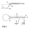
- the execution advanced in figure 1 is configured by a tubular elastic seal, with wing shapes (1) that act as a handle and sliding configuration to seal elbowed edges, by way of their insertion either through its slanted side cut end (3), or through the opposite free end (3) rounded top (4) inside a slot (5) arranged in the direction of the ruling lines and a shorter one (6), diagonally opposite and located on the side opposite the ladle (7), with a base plate (8), which ladle is used to dispense products contained in the bag sealed by it, seal and ladle being joined by way of a lower flange (9), located in the direction of the slot and using up the slanted cut (2) to facilitate the insertion and handling of the ladle inside the container.
- wing shapes (1) that act as a handle and sliding configuration to seal elbowed edges, by way of their insertion either through its slanted side cut end (3), or through the opposite free end (3) rounded top (4) inside a slot (5) arranged in the direction of the ruling lines and a
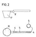
- the execution advanced by figure 2 is configured by an equally tubular elastic seal, but without side wings and sliding to seal the edges of simple straight containers, by way of their introduction through any of its ends, fitted with rounded tops (4) into a slot arranged in the direction of the running lines and joined to the ladle (7'), with internal reinforcements (10), which ladle is used to dispense products from the bag that is seals, in a lower position and being seal and ladle joined by a backing strip (9') elbow shaped and reinforced located below the seal and in the direction of the slot.
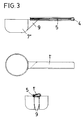
- the execution proposed by figure 3 is configured by an elastic seal, shaped as a short cored and long winged (1') overturned “U”, sliding to seal simple straight edges, by way of their introduction through its rounded top end (4) into a slot (5) configured by the approximation of the free edges of these wings, also rounded and where the ladle (7'') used to dispense the products of the bag that it seals is located in a lower position, being both seal and ladle joined to each other by way of flanges (9) located on the lower surface of the wing acting as a handle and orthogonally placed in respect of the slot.
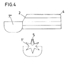
- the execution illustrated in figure 4 is configured by an elastic seal, with an irregular six pointed (1'') star handle, the two opposite vertical star points being of a greater size and the upper one being configured as two cut off wings that near each other to close simple straight container edges, by way of their introduction through their rounded top end (4) into a slot (5) configured by the approximation of the free edges of these wings, also round and being the product dispensing ladle (7''') and to dispense products from the bag sealed by it, located on a lower position and being seal and ladle joined by way of the star points (1) making up the handle.
Landscapes
- Physics & Mathematics (AREA)
- Fluid Mechanics (AREA)
- General Physics & Mathematics (AREA)
- Packages (AREA)
Priority Applications (1)
| Application Number | Priority Date | Filing Date | Title |
|---|---|---|---|
| EP95500079A EP0746997A1 (fr) | 1995-06-06 | 1995-06-06 | Fermeture coulisante incluant une cuillère |
Applications Claiming Priority (1)
| Application Number | Priority Date | Filing Date | Title |
|---|---|---|---|
| EP95500079A EP0746997A1 (fr) | 1995-06-06 | 1995-06-06 | Fermeture coulisante incluant une cuillère |
Publications (1)
| Publication Number | Publication Date |
|---|---|
| EP0746997A1 true EP0746997A1 (fr) | 1996-12-11 |
Family
ID=8221655
Family Applications (1)
| Application Number | Title | Priority Date | Filing Date |
|---|---|---|---|
| EP95500079A Withdrawn EP0746997A1 (fr) | 1995-06-06 | 1995-06-06 | Fermeture coulisante incluant une cuillère |
Country Status (1)
| Country | Link |
|---|---|
| EP (1) | EP0746997A1 (fr) |
Cited By (1)
| Publication number | Priority date | Publication date | Assignee | Title |
|---|---|---|---|---|
| US20120198930A1 (en) * | 2011-02-08 | 2012-08-09 | Progressive International Corporation | Snap-fit measuring container |
Citations (2)
| Publication number | Priority date | Publication date | Assignee | Title |
|---|---|---|---|---|
| GB2029203A (en) * | 1978-09-04 | 1980-03-19 | Fredlunds Ingenjorsbyra Ab | Combined container closure and handle |
| WO1993014680A1 (fr) * | 1992-02-03 | 1993-08-05 | The Procter & Gamble Company | Dispositif multifonction servant a recevoir et verser un produit fluide et a fermer un sac flexible |
-
1995
- 1995-06-06 EP EP95500079A patent/EP0746997A1/fr not_active Withdrawn
Patent Citations (2)
| Publication number | Priority date | Publication date | Assignee | Title |
|---|---|---|---|---|
| GB2029203A (en) * | 1978-09-04 | 1980-03-19 | Fredlunds Ingenjorsbyra Ab | Combined container closure and handle |
| WO1993014680A1 (fr) * | 1992-02-03 | 1993-08-05 | The Procter & Gamble Company | Dispositif multifonction servant a recevoir et verser un produit fluide et a fermer un sac flexible |
Cited By (2)
| Publication number | Priority date | Publication date | Assignee | Title |
|---|---|---|---|---|
| US20120198930A1 (en) * | 2011-02-08 | 2012-08-09 | Progressive International Corporation | Snap-fit measuring container |
| US8806935B2 (en) * | 2011-02-08 | 2014-08-19 | Progressive International Corporation | Snap-fit measuring container |
Similar Documents
| Publication | Publication Date | Title |
|---|---|---|
| EP0251590B1 (fr) | Capuchon pour réceptacle | |
| US5158191A (en) | Dual bottle container having a dual outlet cap | |
| US4022352A (en) | Container cover and safety closure | |
| CA2067232C (fr) | Contenant distributeur | |
| US8403161B2 (en) | Package | |
| US4456135A (en) | Handle and reseal for flanged bottle | |
| US3911578A (en) | Spoon constructions | |
| EP0023786A1 (fr) | Bouchon distributeur en une seule pièce | |
| EP0875485A3 (fr) | Couvercle et réservoir pour la distribution de liquides tels que des colles | |
| EP0326743A3 (fr) | Fermeture de récipient à soupape | |
| CA2136690A1 (fr) | Bouchon amovible pour saupoudreuse reutilisable | |
| AU3706484A (en) | Container with spout and dispensing closure | |
| ATE55745T1 (de) | Wiederverschliessbarer einfach zu oeffnender behaelter mit einer schenklippe und einer geoeffnet haltenden vorrichtung versehen. | |
| IE900282L (en) | Stand-up bag | |
| EP0869072A3 (fr) | Récipient à poignée déplaçable entre deux positions | |
| AU586000B2 (en) | A pouring edge on packing containers | |
| CA2625430A1 (fr) | Dispositif de prelevement et de transport d'echantillon liquide | |
| HU214254B (hu) | Záró adagoló berendezés palackokhoz | |
| US3228444A (en) | Specimen container | |
| AU683667B2 (en) | Dispenser for drugs in solid form | |
| CA1303865C (fr) | Ouvre-canette a onglet | |
| US4768887A (en) | Method for discharging liquid stored in flexible sealed bag and flexible sealed bag for storing liquid | |
| GB2331284A (en) | A container including a non-resealable closure device and an auxiliary sealing device | |
| EP0832824A3 (fr) | Récipient pour produits granulaires, notamment du café, et support associé pour le vider dans un moulin à café | |
| CA2076564A1 (fr) | Squelette de conditionnement |
Legal Events
| Date | Code | Title | Description |
|---|---|---|---|
| PUAI | Public reference made under article 153(3) epc to a published international application that has entered the european phase |
Free format text: ORIGINAL CODE: 0009012 |
|
| AK | Designated contracting states |
Kind code of ref document: A1 Designated state(s): AT BE CH DE DK ES FR GB GR IE IT LI LU MC NL PT SE |
|
| 17P | Request for examination filed |
Effective date: 19970514 |
|
| 17Q | First examination report despatched |
Effective date: 19980405 |
|
| STAA | Information on the status of an ep patent application or granted ep patent |
Free format text: STATUS: THE APPLICATION IS DEEMED TO BE WITHDRAWN |
|
| 18D | Application deemed to be withdrawn |
Effective date: 19980818 |