EP0747030A2 - Appareil de transport et de soins médicaux pour patients - Google Patents
Appareil de transport et de soins médicaux pour patients Download PDFInfo
- Publication number
- EP0747030A2 EP0747030A2 EP96107577A EP96107577A EP0747030A2 EP 0747030 A2 EP0747030 A2 EP 0747030A2 EP 96107577 A EP96107577 A EP 96107577A EP 96107577 A EP96107577 A EP 96107577A EP 0747030 A2 EP0747030 A2 EP 0747030A2
- Authority
- EP
- European Patent Office
- Prior art keywords
- patient
- care apparatus
- frame structure
- platform
- support
- Prior art date
- Legal status (The legal status is an assumption and is not a legal conclusion. Google has not performed a legal analysis and makes no representation as to the accuracy of the status listed.)
- Granted
Links
Images












Classifications
-
- A—HUMAN NECESSITIES
- A61—MEDICAL OR VETERINARY SCIENCE; HYGIENE
- A61G—TRANSPORT, PERSONAL CONVEYANCES, OR ACCOMMODATION SPECIALLY ADAPTED FOR PATIENTS OR DISABLED PERSONS; OPERATING TABLES OR CHAIRS; CHAIRS FOR DENTISTRY; FUNERAL DEVICES
- A61G7/00—Beds specially adapted for nursing; Devices for lifting patients or disabled persons
- A61G7/10—Devices for lifting patients or disabled persons, e.g. special adaptations of hoists thereto
- A61G7/1001—Devices for lifting patients or disabled persons, e.g. special adaptations of hoists thereto specially adapted for specific applications
- A61G7/1011—Picking up from the floor
-
- A—HUMAN NECESSITIES
- A61—MEDICAL OR VETERINARY SCIENCE; HYGIENE
- A61G—TRANSPORT, PERSONAL CONVEYANCES, OR ACCOMMODATION SPECIALLY ADAPTED FOR PATIENTS OR DISABLED PERSONS; OPERATING TABLES OR CHAIRS; CHAIRS FOR DENTISTRY; FUNERAL DEVICES
- A61G1/00—Stretchers
- A61G1/02—Stretchers with wheels
- A61G1/0206—Stretchers with wheels characterised by the number of supporting wheels if stretcher is extended
- A61G1/0212—2 pairs having wheels within a pair on the same position in longitudinal direction, e.g. on the same axis
-
- A—HUMAN NECESSITIES
- A61—MEDICAL OR VETERINARY SCIENCE; HYGIENE
- A61G—TRANSPORT, PERSONAL CONVEYANCES, OR ACCOMMODATION SPECIALLY ADAPTED FOR PATIENTS OR DISABLED PERSONS; OPERATING TABLES OR CHAIRS; CHAIRS FOR DENTISTRY; FUNERAL DEVICES
- A61G1/00—Stretchers
- A61G1/02—Stretchers with wheels
- A61G1/0287—Stretchers with wheels having brakes, e.g. slowing down and/or holding
-
- A—HUMAN NECESSITIES
- A61—MEDICAL OR VETERINARY SCIENCE; HYGIENE
- A61G—TRANSPORT, PERSONAL CONVEYANCES, OR ACCOMMODATION SPECIALLY ADAPTED FOR PATIENTS OR DISABLED PERSONS; OPERATING TABLES OR CHAIRS; CHAIRS FOR DENTISTRY; FUNERAL DEVICES
- A61G1/00—Stretchers
- A61G1/02—Stretchers with wheels
- A61G1/0293—Stretchers with wheels stretcher supports with wheels, e.g. used for stretchers without wheels
-
- A—HUMAN NECESSITIES
- A61—MEDICAL OR VETERINARY SCIENCE; HYGIENE
- A61G—TRANSPORT, PERSONAL CONVEYANCES, OR ACCOMMODATION SPECIALLY ADAPTED FOR PATIENTS OR DISABLED PERSONS; OPERATING TABLES OR CHAIRS; CHAIRS FOR DENTISTRY; FUNERAL DEVICES
- A61G7/00—Beds specially adapted for nursing; Devices for lifting patients or disabled persons
- A61G7/05—Parts, details or accessories of beds
- A61G7/053—Aids for getting into, or out of, bed, e.g. steps, chairs, cane-like supports
- A61G7/0533—Lifting poles
-
- A—HUMAN NECESSITIES
- A61—MEDICAL OR VETERINARY SCIENCE; HYGIENE
- A61G—TRANSPORT, PERSONAL CONVEYANCES, OR ACCOMMODATION SPECIALLY ADAPTED FOR PATIENTS OR DISABLED PERSONS; OPERATING TABLES OR CHAIRS; CHAIRS FOR DENTISTRY; FUNERAL DEVICES
- A61G7/00—Beds specially adapted for nursing; Devices for lifting patients or disabled persons
- A61G7/10—Devices for lifting patients or disabled persons, e.g. special adaptations of hoists thereto
- A61G7/1013—Lifting of patients by
- A61G7/1015—Cables, chains or cords
-
- A—HUMAN NECESSITIES
- A61—MEDICAL OR VETERINARY SCIENCE; HYGIENE
- A61G—TRANSPORT, PERSONAL CONVEYANCES, OR ACCOMMODATION SPECIALLY ADAPTED FOR PATIENTS OR DISABLED PERSONS; OPERATING TABLES OR CHAIRS; CHAIRS FOR DENTISTRY; FUNERAL DEVICES
- A61G7/00—Beds specially adapted for nursing; Devices for lifting patients or disabled persons
- A61G7/10—Devices for lifting patients or disabled persons, e.g. special adaptations of hoists thereto
- A61G7/104—Devices carried or supported by
- A61G7/1046—Mobile bases, e.g. having wheels
-
- A—HUMAN NECESSITIES
- A61—MEDICAL OR VETERINARY SCIENCE; HYGIENE
- A61G—TRANSPORT, PERSONAL CONVEYANCES, OR ACCOMMODATION SPECIALLY ADAPTED FOR PATIENTS OR DISABLED PERSONS; OPERATING TABLES OR CHAIRS; CHAIRS FOR DENTISTRY; FUNERAL DEVICES
- A61G7/00—Beds specially adapted for nursing; Devices for lifting patients or disabled persons
- A61G7/10—Devices for lifting patients or disabled persons, e.g. special adaptations of hoists thereto
- A61G7/1049—Attachment, suspending or supporting means for patients
- A61G7/1055—Suspended platforms, frames or sheets for patient in lying position
-
- A—HUMAN NECESSITIES
- A61—MEDICAL OR VETERINARY SCIENCE; HYGIENE
- A61G—TRANSPORT, PERSONAL CONVEYANCES, OR ACCOMMODATION SPECIALLY ADAPTED FOR PATIENTS OR DISABLED PERSONS; OPERATING TABLES OR CHAIRS; CHAIRS FOR DENTISTRY; FUNERAL DEVICES
- A61G7/00—Beds specially adapted for nursing; Devices for lifting patients or disabled persons
- A61G7/10—Devices for lifting patients or disabled persons, e.g. special adaptations of hoists thereto
- A61G7/1073—Parts, details or accessories
- A61G7/108—Weighing means
-
- G—PHYSICS
- G01—MEASURING; TESTING
- G01G—WEIGHING
- G01G19/00—Weighing apparatus or methods adapted for special purposes not provided for in the preceding groups
- G01G19/44—Weighing apparatus or methods adapted for special purposes not provided for in the preceding groups for weighing persons
- G01G19/445—Weighing apparatus or methods adapted for special purposes not provided for in the preceding groups for weighing persons in a horizontal position
-
- A—HUMAN NECESSITIES
- A61—MEDICAL OR VETERINARY SCIENCE; HYGIENE
- A61G—TRANSPORT, PERSONAL CONVEYANCES, OR ACCOMMODATION SPECIALLY ADAPTED FOR PATIENTS OR DISABLED PERSONS; OPERATING TABLES OR CHAIRS; CHAIRS FOR DENTISTRY; FUNERAL DEVICES
- A61G2200/00—Information related to the kind of patient or his position
- A61G2200/30—Specific positions of the patient
- A61G2200/32—Specific positions of the patient lying
Definitions
- the present invention relates broadly to apparatus for lifting and moving hospital patients within the hospital environment and, more specifically, to a patient transport and care apparatus for use when transporting human or animal hospitalized patients in a hospital environment without significant imposition on the patient.
- a hospital stay means loss of mobility for some patients, dependent on the nature of their respective medical problems. Patients who have experienced loss of mobility present a unique problem for hospital personnel when faced with patient movement and other patient functions. Functions normally performed relying on the patient's locomotion include weight measurement and general movement throughout the hospital environment, typically associated with medical testing procedures. Additionally, for those unfortunate enough to be delivered to the hospital emergency room, transportation must be arranged between the emergency room and operating rooms or patient care rooms.
- the techniques employed for lifting and transport can reduce the chance of injury. Nevertheless, the problem of lifting a patient is not merely one of overcoming significant mass under the force of gravity.
- the patient's physical condition including overall shape, deformities, and other physical impairments, may affect the way a transfer can be carried out.
- some patients can be uncooperative, combative, or even violent.
- the violence may manifest itself suddenly, requiring extra effort on behalf of the hospital personnel. Therefore, optimum body postures as advocated with lifting techniques cannot always be assumed due to the aforesaid patient problems as well as space limitations, equipment handling and furniture interference. As is often the case, reality can overwhelm even the most finely honed learned techniques.
- Still another object of the present invention is to provide such an apparatus which can provide transportable support for patient care accessories.
- a patient support area is defined by the frame structure which is formed of a size and configuration to be selectively movable in and out of a generally surrounding relationship with a floor-standing patient support structure, such as a table, bed or gurney.
- the frame structure includes at least one open end portion for providing access to the patient support area when rolling the frame structure in and out of the surrounding relationship with the floor-standing patient support structure.
- the apparatus further includes at least one gate hingedly mounted to the frame structure adjacent the open end portion and movable between an opened condition away from the end portion for rolling movement of the frame structure into and out of said surrounding relationship and a closed condition in covering relation with the open end portion.
- the apparatus further includes an assembly for supporting a patient, the assembly being selectively mountable to the frame and movable between a patient support disposition and a storage disposition.
- the frame structure preferably includes a superstructure projecting upwardly beyond the patient support area.
- the superstructure has a plurality of horizontally oriented support members. It is preferred that the frame structure include a power distribution system thereassociated.
- the present invention preferably includes an assembly for lifting the patient support assembly within the frame structure and the lifting assembly is mounted to the frame structure. It is further preferred that a weighing assembly be mounted to the frame structure in association with the lifting assembly.
- the weighing assembly includes a scale which also includes a load cell operatively connected to the patient support assembly with the load cell producing an electrical signal proportional to the gravitational force exerted on the patient support assembly for displaying a numerical value associated with the gravitation force responsive to input from the load cell.
- the lifting assembly includes an electric motor, a geared transmission operatively connected thereto, with the electric motor and the transmission being mounted to the horizontally oriented support members of the superstructure.
- the lifting assembly further includes an assembly for operatively connecting the electric motor and the transmission to patient support assembly and the assembly for selectively controlling the operation of the lifting assembly.
- the electric motor is a DC motor and the lifting assembly further includes an arrangement for storing and supplying DC electric power associated with the DC motor, which is preferably a battery.
- an assembly is provided for charging the electric power storage arrangement, and an assembly for supplying electric power from the electrical power distribution system to the charging system is provided.
- the patient support assembly include a flexible patient support platform formed from flexible sheet material and supportable along side edges thereof by the frame structure.
- the platform is selectively movable transversely across the patient support area between a gathered, storage position and an extended position for patient support.
- the platform include at least one rigid pole attached thereto and extending longitudinally with respect to the platform.
- the frame structure then preferably includes a plurality of hooking clamps mounted thereto for engaging and retaining the pole, and thereby the platform, to maintain the platform at a predetermined position.
- the platform may include a plurality off grommeted openings formed therein and positioned for use as anchoring locations for patient restraint devices.
- the platform may also include at least one vertically extending barrier portion projecting upwardly from the platform adjacent the side edges thereof for preventing lateral patient movement beyond side edges of the platform.
- the barrier portion is formed integrally with and from the same sheet material as the platform and includes an assembly to retain and support patient care equipment thereon.
- the arrangement to support and retain patient care equipment includes at least one pocket attached to an inwardly directed surface of the barrier portion, which is configured to retain a bedpan.
- the frame structure include at least one brake operably attached to at least one of the plurality of wheels, the brake being operable to selectively prevent unwanted rolling motion of the apparatus.
- the patient support assembly include two patient support platforms formed from flexible sheet material and supportable along side edges thereof by the frame structure.
- the platforms are mounted to the frame structure with one platform disposed in a spaced vertical relationship with the other platform.
- the platforms are both movable across the patient support area between a gathered, storage position and an extended position for patient support.
- the lifting assembly includes a pair of support braces operatively connected to the electric motor and selectively attachable to and detachable from the patient support assembly for selectively lifting a patient.
- the support braces are movable between a storage position and an operative position and the superstructure includes an arrangement for retaining the support braces in the storage position.
- the frame structure is open at one end for rolling movement into and out of a surrounding relationship with the floor-standing patient support structure.
- the present invention further includes at least one gate hingedly mounted to the frame adjacent the open end portion and movable between an opened condition away from the at least one open end portion for rolling movement of the frame structure in and out of the surrounding relationship and a closed condition in covering relation with the open end portion.
- the present invention provides an assembly for caring for a patient mounted to the frame structure.
- the patient care assembly includes at least one of an oxygen bottle and an assembly for administering oxygen to a patient, an assembly for conducting an endotracheal intubation and a medication supply.
- a shelf may be adjustably mounted to the superstructure with the shelf having a rotatable turntable mounted thereto and movable between a storage position and a usage position, the shelf and turntable being for the support of medical patient monitoring equipment.
- the superstructure also may include a plurality of tubular cross members having a plurality of utility hooks slidably mounted thereto.
- the present invention may include a mirror for reflecting images mounted to the superstructure in a configuration for an operator to view the image of a patient supported on the patient support means.
- a patient trapeze may also be suspended from the superstructure for patient initiated patient stabilization and support.
- An assembly is mounted to the superstructure for storing the trapeze when not in use.
- a second platform may be mounted to the frame structure to assist in moving multiple patients in the event of a disaster or other inconvenience.
- at least one of the patient support platforms includes a plurality of wheels mounted along two side edges thereof, and the frame structure includes two raceways, or tracks, for supporting the wheels during rolling movement thereof and when the at least one platform is stationarily mounted thereto.
- an assembly for releasably latching the wheel platform onto the frame structure with the wheel supported by the raceway is provided.
- the frame structure may include a plurality of hooks disposed at a position lower than that at which a patient is supported for suspending drainage bags therefrom.
- a privacy curtain is provided which is movably mounted to the frame structure and selectively movable in and out of covering relation with a portion of the skeletal frame structure to provide selective privacy for a patient supported on the patient support assembly.
- the present invention provides an apparatus beneficial to both patient and attendant.
- the device may be easily wheeled over a bed and the patient transferred from the bed to the apparatus.
- the apparatus provides the necessary equipment and accessories for caring for a patient in a convenient location away from patient interference.
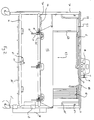
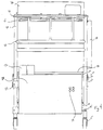
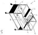
- an apparatus for patient transport and care is illustrated generally at 10 and includes a generally rectangular, skeletal frame structure 12 having a superstructure 14 formed integrally therewith and projecting upwardly therefrom.
- the mid-portion of the interior of the frame structure 12 defines a patient support area 17 and the superstructure projects upwardly from this area.
- the frame structure 12 itself includes four vertical support members 30 positioned at the outer comers of the frame structure 12 and each vertical support member 30 is linked to the other vertical supports members 30 by a pair of lower longitudinally extending cross members 16, a pair of mid-level longitudinally extending cross member 20 having the primary patient support area 17 extending therebetween and a pair of upper longitudinally extending cross members 24.
- the vertical cross members 30 are also linked on one end by a mid-level horizontal transversely extending cross member 22, a first upper horizontal transversely extending cross member 26 and a second upper horizontal transversely extending cross member 27 disposed adjacent the upper ends of the vertical cross members 30.
- a CPR back board 34 is fastened to one end of the frame structure 12 while a gate 28 is attached to the other end of the frame structure 12 using hinges 29.
- a curtain hook track 31 extends around the perimeter of the frame structure 12 adjacent the upper horizontal cross members 24,27.
- a plurality of transversely extending cross braces 25 extends between the uppermost horizontal longitudinally extending cross members 24 to provide a mount for a lifter assembly 36 as will be seen in greater detail hereinafter.
- a wheel assembly 15 is mounted to the lowermost portions of each of the vertical support members 30 to allow rolling movement of the apparatus 10 along a smooth surface. At least one wheel assembly 15 is provided with a brake 23 to prevent unwanted rolling movement of the apparatus 10.
- a flexible patient support platform 40 is provided as seen in Figs. 1 and 6.
- the patient support platform 40 is formed from flexible sheet material so that it may be selectively movable transversely across the patient support area 17, or removed from the apparatus 10 altogether, as will be seen in greater detail hereinafter.
- Two longitudinally extending poles 48 are fitted into envelopes formed on side edges of the platform 40 and extend the full length thereof to add rigidity and support to the platform 40.
- Two barrier members 42 are formed as planar flexible sheets which extend upwardly from the side edges of the platform 40.
- the barriers 42 may be formed integrally with the patient support platform 40.
- a plurality of generally C-shaped handles 45 are attached to the support poles 48 for gripping and lifting.
- Pockets 44 are formed on the inner surface of the barriers 42 to accommodate bed pans or other patient care accessories. Additionally, a plurality of grommeted openings 46 are provided in the support platform 40 for attachment of any necessary patient restraint devices (not shown). As will be seen throughout, the present invention is adapted to provide efficient patient transportation and care along the way.
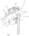
- the latching assemblies 50 include a generally circular rotator sleeve 56 which extends around the mid-level longitudinally extending horizontal cross member 20 with a generally elongate handle 52 projecting tangentially away from the rotator sleeve 56.
- a generally C-shaped gripping member 54 extends radially outwardly from the rotator sleeve 56 at a position approximately 100° away from the handle 52.
- a lock pin 57 is mounted to a support bracket 59 which is in turn mounted to the horizontal cross member 20 adjacent the latching assembly 50.
- the support bracket 59 is a generally rectangular block having the lock pin 57 movably mounted therein.
- a generally elongate handle 58 extends downwardly from the lock pin and is movable between a latched position wherein the lock pin 57 extends inwardly into a corresponding opening in the rotator sleeve 56 which is placed in registry with the opening in the mounting member 59 to receive the lock pin 57.
- the latching assembly 50 provides a sure-fitting, quick-release latch to hold the patient support platform 40 in a patient support configuration.
- the frame structure 12 includes and open end portion 12' and the frame structure 12 itself is sized to enter into a surrounding relationship with a typical hospital bed or examining table.
- a gate 28 is provided and is formed as a generally rectangular planar member mounted to a vertical support member 30 using hinges 29. As may be expected, the gate 28 may be entirely removed without departing from the spirit of the present invention. However, and as will be seen, the gate provides a useful support for other elements of the apparatus 10.
- the gate 28 may be moved from a closed position as seen in Fig. 4 to an open position as seen in Fig. 5 for rolling the apparatus 10 into a surrounding relationship with the patient support structure (not shown in Figs. 4 or 5).
- the gate 28 may be returned to a closed position as seen in Fig. 4 after the apparatus 10 is removed from its surrounding relationship with the patient support structure.
- the present invention also includes an assembly for lifting and weighing patients.
- a housing 38 is mounted to the superstructure 14 along the uppermost horizontal, transversely extending support members 25.
- an electric motor 90 which is preferentially a DC motor, is mounted in the housing 38 in operational, mechanical communication with a transmission 92.
- mechanical power is available at a transmission output 93 which is operationally attached to a pair of bowed support braces 35 which are suspended by a support ring 32 from the superstructure, as best seen in Fig. 2.
- the support braces 35 have a hook 37 formed at each end thereof. The hook 37 is configured to engage and be retained by handles 55 formed on the patient support platform 40.
- the hooks 37 are selectively attachable to and detachable from the handles 55. As will be seen, when the hooks 37 are attached to the handles 55, the latch assembly 50 may be moved into a delatching position and the patient support platform 40 will then be supported by the support braces 35. Using conventional motor controls 91, as indicated in Fig. 9, the motor 90 may be selectively activated to raise or lower the support braces and, accordingly, the patient platform 40.
- the transmission 92 allows the use of a lower powered motor than would be required if the lifting mechanism were directly driven.
- load cell 94 is operationally connected to the transmission 92 to receive and monitor the downwardly directed force caused by any weight on the platform 40 and emit an electrical signal proportional to that force.
- the electrical signal is processed by conventional circuitry 100 and its output displayed on conventional indicators 41.
- the indicators 41 are mounted to the housing 38 and are provided to display the electrical signal proportional to force measurement as a weight.
- control switches 39 are provided adjacent the indicators 41 to selectively operate the control circuit 41 and, thusly, the electric motor 90.
- the motor 90 is a DC motor so that the motor may be operational under the influence of a battery 98 rather than requiring an AC electrical hook-up.
- a battery charger 96 is provided to conveniently charge the battery.
- an electrical distribution system 74 is enclosed in the framework of the present invention.
- the power input 73 illustrated in Fig. 9 is shown in Fig. 4 as an extension cord 75 which is mounted on a reel (not shown) within the gate 28 and may be plugged into a wall outlet.
- the aforesaid battery charger 96 may be connected to the power distribution system 74 using its own retractable power cord (not shown).
- power outputs 79 illustrated as a plurality of electrical outlets 74 in Fig. 4, are provided on the outer surface of the gate 28 which are also part of the electrical distribution system 74 of the present invention.
- a generally rectangular shelf 67 is formed as a tray and extends transversely across the width of the superstructure 14 and is slidably mounted to posts 68 which are in turn mounted to the superstructure 14.
- a turntable 70 is positioned within the shelf.
- the shelf 67 is movable between a stowage position as illustrated in Fig. 2 and a usage position as illustrated in Fig. 1. As may be expected, the shelf 67 may be fixed in the stowage position using a spring-biased pin (not shown). Both the shelf 67 and the turntable 70 provide storage for medical equipment. Additional support structures are provided to hold various equipment.
- a horizontal support bar 84 Adjacent the shelf 67 and on the opposite end of the apparatus 10 from the shelf 67, a horizontal support bar 84 extends transversely across the width of the superstructure 14 and a plurality of J-shaped members 86 projects downwardly from the support bar 84 into attachment with the first upper horizontal transversely extending cross member 26.
- the shelf 67 is designed to support a portable cardiac monitor (not shown) and the monitor display itself may be placed on the turntable 70 for easy movement into viewing range of a care giver.
- Hooks 82 are mounted to the vertical support members 30 to support IV bags or miscellaneous equipment.
- a privacy curtain 78 is mounted to the upper support members 24,27 to provide selective privacy for a patient.
- Other items which may be transported on the device include the patient records, intravenous pumps and fluids, an oxygen tank 72 and associated tubing, blood pressure monitor, cardiac monitor and defibrillator, CPR backboard, respiratory therapy kit, ventilator, emergency medication and equipment, as well as the patient's personal belongings and personal medications.
- a plurality of hooks 85 are disposed around the lower perimeter of the frame structure 12 to support drainage bags at a level below that at which the patient is supported, as best seen in Fig. 2. However, under normal conditions, the device will not be required to support every item on the list at once. Further, the list should not be construed as limiting the present invention in any way but by merely suggesting possible uses for and thereby illustrating the advantages of the present invention over the state of the art.
- a second patient platform 60 may be used when circumstances require the simultaneous transportation of more than one patient.
- the second patient platform 60 could be used to hold equipment.
- the second patient support platform 60 includes a perimetorial rail member 63 having a plurality of generally C-shaped handles 61 projecting upwardly therefrom.
- a patient support surface 65 formed from flexible sheet material, extends within the boundaries of and is mounted to the perimeter rail 63.
- a plurality of wheels 62 project outwardly from the rail 63 and are configured to engage a track 21 formed in the lower horizontal transversely extending cross member 20.
- a latching mechanism 64 engages and retains one of the handles 61. By moving the wheels 62 along the track 21, the second patient support platform 60 may be moved into and out of a spaced vertical relationship with the first patient platform 40.
- a patient P is in place on the patient support platform 40.
- Fig. 10 illustrates a normal transport condition.
- many details of the invention are omitted in Figs. 10-25. This should not be construed as limiting the scope of the present invention in any way and the details are merely omitted for clarity.
- the support braces 35 are lowered into a position wherein the hooks 37 associated with each brace are engaged with the handles 55 associated with the patient support platform 40 at one end corner per hook 37.
- a motor switch 39' is moved into an "on" position and the motor 90 causes the patient support platform 40 to lift beyond the mid-level horizontal longitudinally extending cross members 20 and, when the patient P is supported by only the lifting mechanism, the patient's weight may be read from a meter 41' displayed in the housing 38.
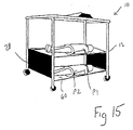
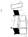
- Figs. 13-15 present a diagrammatical representation of the placement of a patient P, carried on the second platform 60, onto the apparatus 10 of the present invention.
- the gate 28 is opened and, with reference to Fig. 14, the apparatus 10 is rolled into a surrounding relationship with the second patient support platform 60 carrying the patient P.
- the wheels 62 associated with the second patient support platform 60 are mated with the track 21 and the second patient support platform 60 is wheeled into place as seen in Figs. 14 and 15.
- the gate 28 is then closed and the device may be rolled along the floor with the patient P shown in the second patient support platform 60 as seen in Fig. 16.
- the present invention may also be used to transport a patient originally on a conventional hospital bed B, as seen in Fig. 16.
- the gate 28 is opened and the apparatus 10 is aligned with the bed B with the foot portion of the bed B adjacent the open end portion of the apparatus 10.
- the patient support platform 40 is illustrated as being removed entirely from the apparatus 10. It may also remain attached along one side thereof, as previously described.
- the apparatus 10 is rolled into a surrounding relationship with the bed B.
- the patient P is turned by a first attendant A1 onto his side while a second attendant A2 unrolls the flexible patient support platform 40 and attaches the unattached side portion to the apparatus using the latching assemblies 50 as previously discussed.
- the first attendant A1 then rolls the patient P onto his back onto the patient support platform 40 which is by then securely attached on both sides of the transport apparatus 10.
- the apparatus may then be rolled away from the bed B, the gate 28 closed and the patient transported wherever he needs to go.
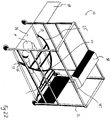
- a patient may also be lifted directly from the floor by the device as illustrated in Figs. 20-23.
- the attendants A1,A2 have removed the patient support platform 40 from the apparatus 10, a portion of which 40' is placed under the patient P, the remainder of the support platform 40 is unrolled and the patient rolled backwardly onto the support platform 40.
- the apparatus 10 with the gate 28 open is rolled over the support platform 40 containing the patient P.
- the support braces 35 are lowered and the hooks 37 associated therewith are engaged with the handles 55 of the patient support platform 40.
- the motor switch 39' is then activated to raise the patient support platform 40 into the patient support area 17, as seen in Fig. 23.
- the latching members are then utilized to latch the patient support platform 40 to the apparatus 10, the gate 28 closed and the patient ready for transport.
- various accessories as also previously described may be mounted on or otherwise attached to the apparatus 10 of the present invention.
- the present invention provides a patient care and transport apparatus which can mechanically move the patient vertically without assistance from any attendant, can weight the patient and can provide convenient carrying access for any patient care equipment and accessories.
- the present invention should contribute greatly to both patient comfort and the health of health care workers.
Landscapes
- Health & Medical Sciences (AREA)
- Life Sciences & Earth Sciences (AREA)
- Animal Behavior & Ethology (AREA)
- General Health & Medical Sciences (AREA)
- Public Health (AREA)
- Veterinary Medicine (AREA)
- Nursing (AREA)
- Physics & Mathematics (AREA)
- General Physics & Mathematics (AREA)
- Invalid Beds And Related Equipment (AREA)
- Prostheses (AREA)
Applications Claiming Priority (2)
| Application Number | Priority Date | Filing Date | Title |
|---|---|---|---|
| US440005 | 1995-05-12 | ||
| US08/440,005 US5570483A (en) | 1995-05-12 | 1995-05-12 | Medical patient transport and care apparatus |
Publications (3)
| Publication Number | Publication Date |
|---|---|
| EP0747030A2 true EP0747030A2 (fr) | 1996-12-11 |
| EP0747030A3 EP0747030A3 (fr) | 1997-05-21 |
| EP0747030B1 EP0747030B1 (fr) | 2001-12-05 |
Family
ID=23747037
Family Applications (1)
| Application Number | Title | Priority Date | Filing Date |
|---|---|---|---|
| EP96107577A Expired - Lifetime EP0747030B1 (fr) | 1995-05-12 | 1996-05-13 | Appareil de transport et de soins médicaux pour patients |
Country Status (4)
| Country | Link |
|---|---|
| US (1) | US5570483A (fr) |
| EP (1) | EP0747030B1 (fr) |
| AT (1) | ATE209885T1 (fr) |
| DE (1) | DE69617529T2 (fr) |
Families Citing this family (36)
| Publication number | Priority date | Publication date | Assignee | Title |
|---|---|---|---|---|
| US6273089B1 (en) | 1996-06-21 | 2001-08-14 | Integrated Medical Systems, Inc. | Automatic mechanical lock down for transportable life support system |
| US6234172B1 (en) | 1996-06-21 | 2001-05-22 | Integrated Medical Systems, Inc. | Control and display configuration layout |
| US5975081A (en) | 1996-06-21 | 1999-11-02 | Northrop Grumman Corporation | Self-contained transportable life support system |
| US6001057A (en) * | 1998-03-26 | 1999-12-14 | Northrop Grumman Corporation | Self-contained isolation and enviromental protection system |
| US6006376A (en) * | 1998-04-03 | 1999-12-28 | Williamson; Ted | Patient lifting and transport apparatus and method |
| US6098216A (en) * | 1998-10-28 | 2000-08-08 | Theodore A. Williamson | Convertible patient transport apparatus and method of transporting a patient |
| US6330926B1 (en) | 1999-09-15 | 2001-12-18 | Hill-Rom Services, Inc. | Stretcher having a motorized wheel |
| GB9921789D0 (en) * | 1999-09-16 | 1999-11-17 | Innes Peter G | Apparatus for a lifting process |
| US7014000B2 (en) | 2000-05-11 | 2006-03-21 | Hill-Rom Services, Inc. | Braking apparatus for a patient support |
| AU2001259757A1 (en) | 2000-05-11 | 2001-11-20 | Hill-Rom Services, Inc. | Motorized traction device for a patient support |
| JP2005502433A (ja) | 2001-09-20 | 2005-01-27 | ヒル−ロム サービシーズ,インコーポレイティド | ベッドムーバと患者移動装置の組合せ |
| US7018157B2 (en) | 2001-09-20 | 2006-03-28 | Hill-Rom Services, Inc. | Powered transport apparatus for a bed |
| JP4509777B2 (ja) * | 2002-06-10 | 2010-07-21 | アスター・テクノロジーズ・エルエルシー | 身体移動システム |
| DE502004000710D1 (de) * | 2004-03-12 | 2006-07-20 | Trumpf Kreuzer Med Sys Gmbh | Medizinischer Gerätewagen mit einer Andockvorrichtung |
| US7882582B2 (en) | 2006-10-13 | 2011-02-08 | Hill-Rom Services, Inc. | User interface and control system for powered transport device of a patient support apparatus |
| US7886377B2 (en) | 2006-10-13 | 2011-02-15 | Hill-Rom Services, Inc. | Push handle with rotatable user interface |
| US7865983B2 (en) | 2007-04-26 | 2011-01-11 | Hill-Rom Services, Inc. | Patient care equipment support transfer system |
| US7818840B2 (en) | 2007-11-09 | 2010-10-26 | Integrated Medical Systems, Inc. | Foldable, portable trauma treatment and monitoring patient platform |
| US8033281B2 (en) * | 2007-11-09 | 2011-10-11 | Todd Douglas Kneale | Modular transportable life support device |
| US7789187B2 (en) | 2008-01-29 | 2010-09-07 | Hill-Rom Services, Inc. | Push handle with pivotable handle post |
| EP2090261B1 (fr) * | 2008-02-18 | 2011-06-01 | General Electric Company | Équipement mobile pour environnement médical |
| US7953537B2 (en) | 2008-02-29 | 2011-05-31 | Hill-Rom Services, Inc. | Algorithm for power drive speed control |
| US8601619B2 (en) * | 2009-03-27 | 2013-12-10 | Astir Technologies, Llc | Body transfer system with yaw control |
| US8757308B2 (en) | 2009-09-10 | 2014-06-24 | Hill-Rom Services Inc. | Powered transport system and control methods |
| KR101150875B1 (ko) * | 2010-03-04 | 2012-06-13 | 계명대학교 산학협력단 | 환자 이송용 기능성 테이블 |
| US8978905B2 (en) | 2010-07-02 | 2015-03-17 | Liko Research & Development Ab | Lift systems with continuous in-rail charging |
| US10022283B2 (en) * | 2010-08-17 | 2018-07-17 | Kevin Wilson Lawless | Platform for patient conveying equipment |
| US8448907B2 (en) * | 2011-03-02 | 2013-05-28 | Laura Witschen | Medical tray having telescoping leg |
| US8584274B2 (en) | 2011-04-22 | 2013-11-19 | Medtrak Holding Company, Llc | Patient support and transport system |
| US8898830B2 (en) | 2011-04-22 | 2014-12-02 | Medtrak Holding Company, Llc | Patient support and transport system of a multimodality medical suite |
| US9707143B2 (en) | 2012-08-11 | 2017-07-18 | Hill-Rom Services, Inc. | Person support apparatus power drive system |
| US9144409B1 (en) * | 2013-11-07 | 2015-09-29 | Gregory J. Ocel | Stretcher compatible with MRI entry systems |
| US9402773B2 (en) * | 2014-05-12 | 2016-08-02 | Gillette Children's Specialty Healthcare | Prone cart |
| US11382436B1 (en) * | 2018-06-14 | 2022-07-12 | Joseph Peter Vosters | Bed frame of a canopy style construction typically found in a home setting integrating assistive components therein |
| WO2020163596A1 (fr) * | 2019-02-06 | 2020-08-13 | Belluscura LLC | Oxygénation extracorporelle intégrée et élimination de co2 à système de ventilation |
| CN111743698B (zh) * | 2020-08-04 | 2022-07-05 | 青岛大学附属医院 | 一种产科临床专用转运装置 |
Family Cites Families (68)
| Publication number | Priority date | Publication date | Assignee | Title |
|---|---|---|---|---|
| US885329A (en) * | 1907-06-15 | 1908-04-21 | James John Ellis | Invalid hammock lift and turner. |
| US1227301A (en) * | 1915-01-06 | 1917-05-22 | William Clark Ogden | Invalid-carrier. |
| US1270136A (en) * | 1917-03-01 | 1918-06-18 | Fannie Finley | Patient's transporting and treating apparatus. |
| US2272778A (en) * | 1939-09-05 | 1942-02-10 | Paul A Reuter | Apparatus for lifting invalids |
| US2627611A (en) * | 1951-04-11 | 1953-02-10 | Cecil C Nichols | Combination invalid stretcher carrier |
| US2873456A (en) * | 1954-11-05 | 1959-02-17 | Joseph F Joy | Bed with invalid lift |
| FR1215158A (fr) * | 1958-11-07 | 1960-04-15 | Appareil pour le déplacement et le transport des malades | |
| US2990899A (en) * | 1958-11-24 | 1961-07-04 | Bella Isabelle D De | Bed patient weighing means |
| US3091286A (en) * | 1962-08-08 | 1963-05-28 | Mads P Madsen | Remotely controlled sick bed curtains |
| US3344445A (en) * | 1966-08-12 | 1967-10-03 | Institutional Ind Inc | Side panel construction for stretcher-beds |
| US3613127A (en) * | 1969-11-05 | 1971-10-19 | James M Bond | Apparatus facilitating care of a bedfast patient |
| DE2103168A1 (de) * | 1971-01-23 | 1972-08-17 | Klein, Heinrich Georg, 4270 Dorsten; Seitz, Rosa, 4350 Recklinghausen | Notkrankentrage-Umbettrahmen mit losem Querholmstabilisator |
| US3877089A (en) * | 1973-05-07 | 1975-04-15 | Mercy Lift Inc | Invalid lift apparatus |
| FR2297604A1 (fr) * | 1975-01-15 | 1976-08-13 | Tuoro Maurice Di | Chariot de transport et de reveil pour malade opere |
| US4000530A (en) * | 1975-06-25 | 1977-01-04 | Booker Green | Invalid handling device |
| US5033563A (en) * | 1976-05-18 | 1991-07-23 | Cardinal Scale Manufacturing Company | Apparatus for weighing a patient on a stretcher |
| FR2369832A1 (fr) * | 1976-11-04 | 1978-06-02 | Bodron Daniel | Portique de reanimation |
| US4232412A (en) * | 1978-11-30 | 1980-11-11 | Bartholomew Petrini | Patient transfer device |
| US4397051A (en) * | 1981-04-30 | 1983-08-09 | Helen S. Ballas | Apparatus for lifting a human being |
| DE3217466A1 (de) * | 1982-05-08 | 1983-11-10 | Brinkmann, Brigitte | Rettungs- und umbettungstuch mit zubehoer |
| US4571758A (en) * | 1983-08-31 | 1986-02-25 | United Air Lines, Inc. | Apparatus for vertically lifting and radially moving a person over a supporting surface |
| US4584989A (en) * | 1984-12-20 | 1986-04-29 | Rosemarie Stith | Life support stretcher bed |
| US4627119A (en) * | 1985-01-22 | 1986-12-09 | Parasystems, Inc. | Apparatus to assist the disabled |
| US4813088A (en) * | 1985-05-07 | 1989-03-21 | Nova Technologies, Inc. | Person transfer arrangement |
| US4837872A (en) * | 1985-05-07 | 1989-06-13 | Nova Technologies, Inc. | Patient transfer arrangement |
| US4686727A (en) * | 1985-06-03 | 1987-08-18 | Lawrence H. Wilkinson | Convenience bar assembly for hospital bed |
| US4839933A (en) * | 1985-08-13 | 1989-06-20 | Plewright William B | Patient transfer and conveying vehicle |
| US4682377A (en) * | 1986-06-27 | 1987-07-28 | Design Mobility, Inc. | Device for transferring immobile persons |
| US4768241A (en) * | 1987-02-24 | 1988-09-06 | Beney Daniel R | Self contained, mobile intensive care bed structure |
| US4723327A (en) * | 1987-04-10 | 1988-02-09 | Smith Walter J | Patient mover |
| US4805248A (en) * | 1987-09-23 | 1989-02-21 | Lunau Kevin R | Invalid transfer lift |
| US4945582A (en) * | 1988-03-11 | 1990-08-07 | Hausted, Inc. | Patient transport apparatus including independently or simultaneously operable leg and backrest portions |
| US4829612A (en) * | 1988-05-16 | 1989-05-16 | Adams James A | Patient transfer apparatus |
| FR2631548B1 (fr) * | 1988-05-19 | 1991-02-22 | Louit Sa | Module autonome de soins intensifs et de reanimation |
| US4957121A (en) * | 1988-07-05 | 1990-09-18 | Arizona Technology Development Corporation | Mobile intensive care patient handling system apparatus and method of using |
| US4944056A (en) * | 1988-09-28 | 1990-07-31 | The Research Foundation Of State University Of Ny | Method and apparatus for transporting a disabled person |
| NL8802874A (nl) * | 1988-11-22 | 1990-06-18 | Philips Nv | Patient positionerings en -transportsysteem, alsmede patienttafel, trolley en tafelblad voor toepassing in een dergelijk systeem. |
| DE3902027C1 (fr) * | 1989-01-25 | 1990-03-29 | Hans 7052 Schwaikheim De Jung | |
| US4964182A (en) * | 1989-02-01 | 1990-10-23 | Joseph Schmerler | Transfer aid with auxiliary support system |
| US5005233A (en) * | 1989-03-15 | 1991-04-09 | Ikka Toivio | Apparatus for transferring patients |
| US5022105A (en) * | 1989-08-04 | 1991-06-11 | Michael Catoe | Mobile lift-assisted patient transport device for field use |
| FI89869C (fi) * | 1989-10-27 | 1993-12-10 | Ahlstroem Kuluttajatuoteet Oy | Baedd |
| US5077844A (en) * | 1989-11-22 | 1992-01-07 | Twitchell Kendel S | Mechanical apparatus for lifting and moving humans |
| US4987623A (en) * | 1990-01-26 | 1991-01-29 | Stryker Corporation | Hospital stretcher having patient transfer device and side rails with handle portions |
| US5005230A (en) * | 1990-03-30 | 1991-04-09 | Massachusetts Eye And Ear Infirmary | Patient transporter |
| DE4015471A1 (de) * | 1990-05-14 | 1991-11-21 | Stierlen Maquet Ag | Mobiles patientenlagersystem |
| US5065464A (en) * | 1990-07-30 | 1991-11-19 | Ssi Medical Services, Inc. | Apparatus for transferring a patient between patient support surfaces |
| CH680833A5 (en) * | 1990-08-14 | 1992-11-30 | Gisela Otte | Childbirth viewing mirror - has reflectve surface hinging on stand foot equipped with clamp to allow mounting on bed |
| US5148557A (en) * | 1990-08-27 | 1992-09-22 | Vladimir Fridman | Invalid lift and transport apparatus |
| US5165838A (en) * | 1990-09-06 | 1992-11-24 | Teledyne Industries, Inc. | Vehicle for transporting loads |
| US5093944A (en) * | 1990-10-19 | 1992-03-10 | Cindylift Products, Inc. | Patient transfer apparatus |
| US5084921A (en) * | 1991-01-18 | 1992-02-04 | Hicks Jr George W | Supine patient lift and transfer apparatus |
| US5148559A (en) * | 1991-04-09 | 1992-09-22 | Morris Charles W | Patient conveyance device |
| US5090072A (en) * | 1991-05-02 | 1992-02-25 | Edward H. Gray | Patient lifting device |
| US5127113A (en) * | 1991-06-10 | 1992-07-07 | Nova Technologies, Inc. | Invalid transfer arrangement |
| US5315723A (en) * | 1991-06-21 | 1994-05-31 | Ary Lift, Inc. | Portable patient turning and lifting apparatus |
| US5153953A (en) * | 1991-06-27 | 1992-10-13 | Sumrall Joe L | Apparatus for transfer of the disabled |
| US5173977A (en) * | 1991-10-04 | 1992-12-29 | Hill-Rom Company, Inc. | Load cell mount for hospital weigh bed |
| US5189741A (en) * | 1991-11-15 | 1993-03-02 | Robert L. Beardmore | Patient lift and transportation device |
| US5251862A (en) * | 1991-12-06 | 1993-10-12 | Walter Raymond | Transporting and lifting apparatus and methods for aiding handicapped individuals |
| GB9126689D0 (en) * | 1991-12-17 | 1992-02-12 | Parker Roy | Invalid hoists |
| US5185895A (en) * | 1992-01-30 | 1993-02-16 | Eugene Gagne | Patient lift and transport aid |
| US5233708A (en) * | 1992-07-30 | 1993-08-10 | Cindylift Products, Inc. | Patient transfer apparatus |
| US5193233A (en) * | 1992-08-20 | 1993-03-16 | Miller Miles S | Patient transfer unit |
| US5319817A (en) * | 1992-09-15 | 1994-06-14 | Andermac, Inc. | Folding patient lift and weighing apparatus |
| US5257425A (en) * | 1992-12-29 | 1993-11-02 | Shinabarger Bob D | Dependent patient transfer device |
| GB2275604B (en) * | 1993-03-02 | 1996-07-31 | Raymond John Holden | Hoist |
| US5271110A (en) * | 1993-05-20 | 1993-12-21 | Newman William C | Patient transfer device |
-
1995
- 1995-05-12 US US08/440,005 patent/US5570483A/en not_active Expired - Fee Related
-
1996
- 1996-05-13 DE DE69617529T patent/DE69617529T2/de not_active Expired - Fee Related
- 1996-05-13 EP EP96107577A patent/EP0747030B1/fr not_active Expired - Lifetime
- 1996-05-13 AT AT96107577T patent/ATE209885T1/de active
Also Published As
| Publication number | Publication date |
|---|---|
| EP0747030B1 (fr) | 2001-12-05 |
| DE69617529T2 (de) | 2002-08-01 |
| ATE209885T1 (de) | 2001-12-15 |
| DE69617529D1 (de) | 2002-01-17 |
| EP0747030A3 (fr) | 1997-05-21 |
| US5570483A (en) | 1996-11-05 |
Similar Documents
| Publication | Publication Date | Title |
|---|---|---|
| US5570483A (en) | Medical patient transport and care apparatus | |
| EP0651619B1 (fr) | Lit d'hopital et materiel medical sur roues et a emboitement | |
| EP0680433B1 (fr) | Dispositif de transport motorise pouvant etre integre dans la partie inferieure d'un lit d'hopital | |
| US4691397A (en) | Life support carrying apparatus | |
| US20150035333A1 (en) | Apparatus for lifting persons | |
| WO2011108873A2 (fr) | Table fonctionnelle pour le transfert de patient | |
| US5579547A (en) | Patient lift-transfer mechanism for gurney | |
| US9038214B2 (en) | Hippa privacy infectious control screen for gurneys and other mobile transportable beds for emergency and other inter and intra healthcare facility transfers | |
| WO2000009061A1 (fr) | Systeme de transfert pour appareil portatif de soins aux malades | |
| CN106038092B (zh) | 急救担架 | |
| CN113786294A (zh) | 一种儿科用智能防坠落病床 | |
| KR102027334B1 (ko) | 환자 감시 및 응급소생처치를 위한 통합 기능성 구급 침상 플랫폼 장치 | |
| CN209916411U (zh) | 一种急救护理组合式担架车 | |
| US6986310B2 (en) | Transporter for vertical movement and lateral transfer of persons having impaired or no self-locomotion | |
| CN215689175U (zh) | 一种应用于转运车上的重症急救装置 | |
| CN110236802A (zh) | 一种空间集约式多功能救护车 | |
| CN213525968U (zh) | 一种便于携带急救与监护设备的急危重病人转运车 | |
| CN213666310U (zh) | 一种病床辅助保护装置 | |
| CN114129360A (zh) | 一种儿科用智能防坠落病床 | |
| CN205548838U (zh) | 用于病人院内转运的转运床 | |
| CN218010201U (zh) | 一种康复护理床 | |
| CN215017671U (zh) | 一种转运危重患者用心电监护仪固定装置 | |
| CN213994039U (zh) | 一种骨科术后用支撑装置 | |
| EP3031433A1 (fr) | Civière de voyage pour transporter un patient, notamment destinée à être utilisée lors d'événements de grande envergure | |
| CN213883873U (zh) | 一种便携式设备转运架 |
Legal Events
| Date | Code | Title | Description |
|---|---|---|---|
| PUAI | Public reference made under article 153(3) epc to a published international application that has entered the european phase |
Free format text: ORIGINAL CODE: 0009012 |
|
| AK | Designated contracting states |
Kind code of ref document: A2 Designated state(s): AT BE CH DE DK ES FI FR GB GR IE IT LI LU MC NL PT SE |
|
| PUAL | Search report despatched |
Free format text: ORIGINAL CODE: 0009013 |
|
| AK | Designated contracting states |
Kind code of ref document: A3 Designated state(s): AT BE CH DE DK ES FI FR GB GR IE IT LI LU MC NL PT SE |
|
| 17P | Request for examination filed |
Effective date: 19970731 |
|
| 17Q | First examination report despatched |
Effective date: 19990223 |
|
| GRAG | Despatch of communication of intention to grant |
Free format text: ORIGINAL CODE: EPIDOS AGRA |
|
| GRAG | Despatch of communication of intention to grant |
Free format text: ORIGINAL CODE: EPIDOS AGRA |
|
| GRAG | Despatch of communication of intention to grant |
Free format text: ORIGINAL CODE: EPIDOS AGRA |
|
| GRAH | Despatch of communication of intention to grant a patent |
Free format text: ORIGINAL CODE: EPIDOS IGRA |
|
| GRAH | Despatch of communication of intention to grant a patent |
Free format text: ORIGINAL CODE: EPIDOS IGRA |
|
| GRAA | (expected) grant |
Free format text: ORIGINAL CODE: 0009210 |
|
| AK | Designated contracting states |
Kind code of ref document: B1 Designated state(s): AT BE CH DE DK ES FI FR GB GR IE IT LI LU MC NL PT SE |
|
| PG25 | Lapsed in a contracting state [announced via postgrant information from national office to epo] |
Ref country code: NL Free format text: LAPSE BECAUSE OF FAILURE TO SUBMIT A TRANSLATION OF THE DESCRIPTION OR TO PAY THE FEE WITHIN THE PRESCRIBED TIME-LIMIT Effective date: 20011205 Ref country code: LI Free format text: LAPSE BECAUSE OF FAILURE TO SUBMIT A TRANSLATION OF THE DESCRIPTION OR TO PAY THE FEE WITHIN THE PRESCRIBED TIME-LIMIT Effective date: 20011205 Ref country code: IT Free format text: LAPSE BECAUSE OF FAILURE TO SUBMIT A TRANSLATION OF THE DESCRIPTION OR TO PAY THE FEE WITHIN THE PRE;WARNING: LAPSES OF ITALIAN PATENTS WITH EFFECTIVE DATE BEFORE 2007 MAY HAVE OCCURRED AT ANY TIME BEFORE 2007. THE CORRECT EFFECTIVE DATE MAY BE DIFFERENT FROM THE ONE RECORDED.SCRIBED TIME-LIMIT Effective date: 20011205 Ref country code: GR Free format text: LAPSE BECAUSE OF FAILURE TO SUBMIT A TRANSLATION OF THE DESCRIPTION OR TO PAY THE FEE WITHIN THE PRESCRIBED TIME-LIMIT Effective date: 20011205 Ref country code: FI Free format text: LAPSE BECAUSE OF FAILURE TO SUBMIT A TRANSLATION OF THE DESCRIPTION OR TO PAY THE FEE WITHIN THE PRESCRIBED TIME-LIMIT Effective date: 20011205 Ref country code: CH Free format text: LAPSE BECAUSE OF FAILURE TO SUBMIT A TRANSLATION OF THE DESCRIPTION OR TO PAY THE FEE WITHIN THE PRESCRIBED TIME-LIMIT Effective date: 20011205 Ref country code: BE Free format text: LAPSE BECAUSE OF FAILURE TO SUBMIT A TRANSLATION OF THE DESCRIPTION OR TO PAY THE FEE WITHIN THE PRESCRIBED TIME-LIMIT Effective date: 20011205 Ref country code: AT Free format text: LAPSE BECAUSE OF FAILURE TO SUBMIT A TRANSLATION OF THE DESCRIPTION OR TO PAY THE FEE WITHIN THE PRESCRIBED TIME-LIMIT Effective date: 20011205 |
|
| REF | Corresponds to: |
Ref document number: 209885 Country of ref document: AT Date of ref document: 20011215 Kind code of ref document: T |
|
| REG | Reference to a national code |
Ref country code: CH Ref legal event code: EP |
|
| REG | Reference to a national code |
Ref country code: GB Ref legal event code: IF02 |
|
| REG | Reference to a national code |
Ref country code: IE Ref legal event code: FG4D |
|
| REF | Corresponds to: |
Ref document number: 69617529 Country of ref document: DE Date of ref document: 20020117 |
|
| PG25 | Lapsed in a contracting state [announced via postgrant information from national office to epo] |
Ref country code: SE Free format text: LAPSE BECAUSE OF FAILURE TO SUBMIT A TRANSLATION OF THE DESCRIPTION OR TO PAY THE FEE WITHIN THE PRESCRIBED TIME-LIMIT Effective date: 20020305 Ref country code: PT Free format text: LAPSE BECAUSE OF FAILURE TO SUBMIT A TRANSLATION OF THE DESCRIPTION OR TO PAY THE FEE WITHIN THE PRESCRIBED TIME-LIMIT Effective date: 20020305 Ref country code: DK Free format text: LAPSE BECAUSE OF FAILURE TO SUBMIT A TRANSLATION OF THE DESCRIPTION OR TO PAY THE FEE WITHIN THE PRESCRIBED TIME-LIMIT Effective date: 20020305 |
|
| NLV1 | Nl: lapsed or annulled due to failure to fulfill the requirements of art. 29p and 29m of the patents act | ||
| ET | Fr: translation filed |
Owner name: CAROLINA NARROW FABRIC COMPANY |
|
| PG25 | Lapsed in a contracting state [announced via postgrant information from national office to epo] |
Ref country code: MC Free format text: LAPSE BECAUSE OF NON-PAYMENT OF DUE FEES Effective date: 20020513 Ref country code: LU Free format text: LAPSE BECAUSE OF NON-PAYMENT OF DUE FEES Effective date: 20020513 Ref country code: IE Free format text: LAPSE BECAUSE OF NON-PAYMENT OF DUE FEES Effective date: 20020513 |
|
| REG | Reference to a national code |
Ref country code: CH Ref legal event code: PL |
|
| PG25 | Lapsed in a contracting state [announced via postgrant information from national office to epo] |
Ref country code: ES Free format text: LAPSE BECAUSE OF FAILURE TO SUBMIT A TRANSLATION OF THE DESCRIPTION OR TO PAY THE FEE WITHIN THE PRESCRIBED TIME-LIMIT Effective date: 20020627 |
|
| PLBE | No opposition filed within time limit |
Free format text: ORIGINAL CODE: 0009261 |
|
| STAA | Information on the status of an ep patent application or granted ep patent |
Free format text: STATUS: NO OPPOSITION FILED WITHIN TIME LIMIT |
|
| 26N | No opposition filed | ||
| REG | Reference to a national code |
Ref country code: IE Ref legal event code: MM4A |
|
| PGFP | Annual fee paid to national office [announced via postgrant information from national office to epo] |
Ref country code: FR Payment date: 20030520 Year of fee payment: 8 |
|
| PGFP | Annual fee paid to national office [announced via postgrant information from national office to epo] |
Ref country code: GB Payment date: 20030521 Year of fee payment: 8 |
|
| PGFP | Annual fee paid to national office [announced via postgrant information from national office to epo] |
Ref country code: DE Payment date: 20030617 Year of fee payment: 8 |
|
| PG25 | Lapsed in a contracting state [announced via postgrant information from national office to epo] |
Ref country code: GB Free format text: LAPSE BECAUSE OF NON-PAYMENT OF DUE FEES Effective date: 20040513 |
|
| PG25 | Lapsed in a contracting state [announced via postgrant information from national office to epo] |
Ref country code: DE Free format text: LAPSE BECAUSE OF NON-PAYMENT OF DUE FEES Effective date: 20041201 |
|
| GBPC | Gb: european patent ceased through non-payment of renewal fee |
Effective date: 20040513 |
|
| PG25 | Lapsed in a contracting state [announced via postgrant information from national office to epo] |
Ref country code: FR Free format text: LAPSE BECAUSE OF NON-PAYMENT OF DUE FEES Effective date: 20050131 |
|
| REG | Reference to a national code |
Ref country code: FR Ref legal event code: ST |