EP0747090A2 - Dispositif de contrÔle du débit des fluides, en particulier pour perfuser des liquides intraveineux - Google Patents
Dispositif de contrÔle du débit des fluides, en particulier pour perfuser des liquides intraveineux Download PDFInfo
- Publication number
- EP0747090A2 EP0747090A2 EP96302999A EP96302999A EP0747090A2 EP 0747090 A2 EP0747090 A2 EP 0747090A2 EP 96302999 A EP96302999 A EP 96302999A EP 96302999 A EP96302999 A EP 96302999A EP 0747090 A2 EP0747090 A2 EP 0747090A2
- Authority
- EP
- European Patent Office
- Prior art keywords
- tube
- passage
- control device
- flow control
- fluid flow
- Prior art date
- Legal status (The legal status is an assumption and is not a legal conclusion. Google has not performed a legal analysis and makes no representation as to the accuracy of the status listed.)
- Granted
Links
Images


Classifications
-
- A—HUMAN NECESSITIES
- A61—MEDICAL OR VETERINARY SCIENCE; HYGIENE
- A61M—DEVICES FOR INTRODUCING MEDIA INTO, OR ONTO, THE BODY; DEVICES FOR TRANSDUCING BODY MEDIA OR FOR TAKING MEDIA FROM THE BODY; DEVICES FOR PRODUCING OR ENDING SLEEP OR STUPOR
- A61M5/00—Devices for bringing media into the body in a subcutaneous, intra-vascular or intramuscular way; Accessories therefor, e.g. filling or cleaning devices, arm-rests
- A61M5/14—Infusion devices, e.g. infusing by gravity; Blood infusion; Accessories therefor
- A61M5/168—Means for controlling media flow to the body or for metering media to the body, e.g. drip meters, counters ; Monitoring media flow to the body
- A61M5/16877—Adjusting flow; Devices for setting a flow rate
-
- A—HUMAN NECESSITIES
- A61—MEDICAL OR VETERINARY SCIENCE; HYGIENE
- A61M—DEVICES FOR INTRODUCING MEDIA INTO, OR ONTO, THE BODY; DEVICES FOR TRANSDUCING BODY MEDIA OR FOR TAKING MEDIA FROM THE BODY; DEVICES FOR PRODUCING OR ENDING SLEEP OR STUPOR
- A61M39/00—Tubes, tube connectors, tube couplings, valves, access sites or the like, specially adapted for medical use
- A61M39/22—Valves or arrangement of valves
- A61M39/28—Clamping means for squeezing flexible tubes, e.g. roller clamps
- A61M39/286—Wedge clamps, e.g. roller clamps with inclined guides
Definitions
- the present invention relates to devices for fluid flow control and, in particular, to such devices when forming part of a system for infusing fluids into the body of a patient.
- the rate of drug injection is critical since excess doses can be toxic.
- a resilient tube of triangular transverse cross-section which is used for transporting parenteral fluid for delivery to a patient.
- the tube extends through a device which includes a housing and a roller.
- the roller is used to squeeze the tube for regulating the flow of fluid therethrough.
- a fluid flow control device comprises a resilient hollow tube having a passage with an internal cross-sectional configuration defined in part by two sides meeting at an apex for the flow therethrough of a fluid and means for applying a pressure to the tube to reduce in a controlled manner the cross-sectional area of the passage, characterised in that the means is located adjacent the tube opposite said apex and movable towards said apex to apply a pressure to the tube.
- the internal cross-sectional configuration is defined by a three-sided passage, the pressure means being aligned with one side of the passage for movement towards the opposite apex.
- the passage has a cross-sectional configuration in the form of a straight-sided equilateral triangle.
- the tube may be made from silicone.
- the resilient hollow tube is located within a housing, which is provided at a location between the ends of the resilient hollow tube with a through aperture within which a steel ball is movable between a first position in which the ball projects into the housing and maintains a portion of the tube in a compressed closed condition and a second position in which the portion is substantially unaffected by the ball.
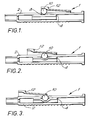
- a fluid flow control device 1 includes a tubular housing 2 made for example of polypropylene which forms part of a system for infusing liquids into the body of a patient.
- a resilient hollow tube 4 made, for example, of silicone.
- the internal cross-sectional configuration of the tube 4 is defined by a three-sided passage 6.
- a through aperture 8 is formed in the housing 2 approximately mid-way between the ends of the tube 4.
- pressure means in the form of a steel ball 10. It is important to note that the ball 10 is aligned with one side (as shown the topside) of the three-sided passage 6 opposite one apex.
- a slide 12 is mounted on the upper (as shown) surface of the housing 2 and is capable of movement longitudinally of the housing 2.
- the slide 12 has an inverted U-shape with a web 14 and two depending flanges 16.
- Each flange 16 includes on its inside surface, a channel 18 adapted to receive a runner 20 formed on the surface of the housing 2.
- the inside surface of the web 14 is inclined as shown in Figures 1 to 3 and engages the upper (as shown) surface of the ball 10.
- the tubular housing 2 forms part of a system for infusing a liquid drug into a patient said liquid will flow through the housing 2 and hence through the three-sided passage 6 in the tube 4.
- the flow rate through the housing 2 may need to be varied from as little as 5ml per hour to as much as 1000ml per hour.
- the ball 10 will apply substantially no pressure to the surface of the tube 4 and the passage 6 will not be occluded. This will allow maximum flow of liquid through the housing 2.
- Figure 3 illustrates the position of the slide 12 and ball 10 when the passage 6 in the tube 4 is completely occluded which prevents the flow of any fluid through the housing 2.
- FIGS. 5a, 5b and 5c illustrate the varying cross-sectional configurations of the passage 6 for varying pressures to the tube 4 applied by the ball 10.
- Figures 6a, 6b and 6c illustrate the manner in which the cross-sectional configuration of a standard circular cross-sectioned tube would alter for the same pressures applied by the ball 10 as per Figures 5a, 5b and 5c.
- the shape of the passage as it is deformed makes it far more difficult to control the rate of change of fluid passing through the passage as compared to a three-sided passage.
- the three-sided passage 6 is shown with straight sides and radiused apices in a preferred embodiment the passage is in the form of an equilateral triangle with sharp corners.
- the sides can be made convex or concave.
Landscapes
- Health & Medical Sciences (AREA)
- Heart & Thoracic Surgery (AREA)
- Animal Behavior & Ethology (AREA)
- General Health & Medical Sciences (AREA)
- Anesthesiology (AREA)
- Biomedical Technology (AREA)
- Hematology (AREA)
- Life Sciences & Earth Sciences (AREA)
- Veterinary Medicine (AREA)
- Engineering & Computer Science (AREA)
- Public Health (AREA)
- Pulmonology (AREA)
- Physics & Mathematics (AREA)
- Fluid Mechanics (AREA)
- Vascular Medicine (AREA)
- Infusion, Injection, And Reservoir Apparatuses (AREA)
- Flow Control (AREA)
Applications Claiming Priority (2)
| Application Number | Priority Date | Filing Date | Title |
|---|---|---|---|
| GBGB9509546.9A GB9509546D0 (en) | 1995-05-11 | 1995-05-11 | Fluid flow control device |
| GB9509546 | 1995-05-11 |
Publications (3)
| Publication Number | Publication Date |
|---|---|
| EP0747090A2 true EP0747090A2 (fr) | 1996-12-11 |
| EP0747090A3 EP0747090A3 (fr) | 1997-04-23 |
| EP0747090B1 EP0747090B1 (fr) | 2002-07-24 |
Family
ID=10774300
Family Applications (1)
| Application Number | Title | Priority Date | Filing Date |
|---|---|---|---|
| EP19960302999 Expired - Lifetime EP0747090B1 (fr) | 1995-05-11 | 1996-04-29 | Dispositif de contrôle du débit des fluides, en particulier pour perfuser des liquides intraveineux |
Country Status (4)
| Country | Link |
|---|---|
| EP (1) | EP0747090B1 (fr) |
| JP (1) | JPH09133229A (fr) |
| DE (1) | DE69622473T2 (fr) |
| GB (1) | GB9509546D0 (fr) |
Cited By (2)
| Publication number | Priority date | Publication date | Assignee | Title |
|---|---|---|---|---|
| CN114306814A (zh) * | 2020-09-29 | 2022-04-12 | 康尔福盛303公司 | 滑动流动控制器 |
| DE102024123920A1 (de) * | 2024-08-21 | 2026-02-26 | B. Braun Melsungen Aktiengesellschaft | Elastomere Infusionspumpe |
Families Citing this family (2)
| Publication number | Priority date | Publication date | Assignee | Title |
|---|---|---|---|---|
| JP3819679B2 (ja) * | 2000-06-16 | 2006-09-13 | 東芝テック株式会社 | エアーマッサージ機 |
| JP5129514B2 (ja) * | 2007-06-05 | 2013-01-30 | 創市 小川 | 水槽用エアポンプ |
Family Cites Families (2)
| Publication number | Priority date | Publication date | Assignee | Title |
|---|---|---|---|---|
| SE445131B (sv) * | 1983-12-14 | 1986-06-02 | Mediplast Ab | Kompressibel slang for transport av sma vetskemengder, i synnerhet for infusionslosningar, samt sett att framstella slangen |
| JPH0316570A (ja) * | 1989-06-14 | 1991-01-24 | Nissho Corp | ローラクランプ |
-
1995
- 1995-05-11 GB GBGB9509546.9A patent/GB9509546D0/en active Pending
-
1996
- 1996-04-29 DE DE1996622473 patent/DE69622473T2/de not_active Expired - Fee Related
- 1996-04-29 EP EP19960302999 patent/EP0747090B1/fr not_active Expired - Lifetime
- 1996-05-07 JP JP8112357A patent/JPH09133229A/ja active Pending
Cited By (2)
| Publication number | Priority date | Publication date | Assignee | Title |
|---|---|---|---|---|
| CN114306814A (zh) * | 2020-09-29 | 2022-04-12 | 康尔福盛303公司 | 滑动流动控制器 |
| DE102024123920A1 (de) * | 2024-08-21 | 2026-02-26 | B. Braun Melsungen Aktiengesellschaft | Elastomere Infusionspumpe |
Also Published As
| Publication number | Publication date |
|---|---|
| JPH09133229A (ja) | 1997-05-20 |
| EP0747090B1 (fr) | 2002-07-24 |
| GB9509546D0 (en) | 1995-07-05 |
| DE69622473D1 (de) | 2002-08-29 |
| DE69622473T2 (de) | 2003-01-23 |
| EP0747090A3 (fr) | 1997-04-23 |
Similar Documents
| Publication | Publication Date | Title |
|---|---|---|
| US4065093A (en) | Flow control device | |
| US4787406A (en) | Fluid flow control clamp and method for using same | |
| US6079432A (en) | Control of fluid flow by oval shaped valve member containing a cam interface | |
| EP0139347B1 (fr) | Assemblage de soupape | |
| US5396925A (en) | Anti-free flow valve, enabling fluid flow as a function of pressure and selectively opened to enable free flow | |
| US7815612B2 (en) | Apparatus and method for preventing free flow in an infusion line | |
| EP1129740B1 (fr) | Appareil de réglage du débit de perfusion d'un distributeur de médicaments | |
| US3893468A (en) | Clamp for flexible tube and method of regulating flow in such tube | |
| US7367963B2 (en) | Apparatus and method for preventing free flow in an infusion line | |
| EP2621560B1 (fr) | Obturateur anti-écoulement libre et tampon actionneur d'amorçage | |
| US5746414A (en) | Fluid access and flow control valve | |
| US4997420A (en) | Portable drug delivery device including pump with tapered barrel | |
| US5704584A (en) | Pinch clip occluder for infusion sets | |
| US4456223A (en) | Flow control apparatus | |
| US5865813A (en) | Intravenous tube occluder | |
| JPS62501820A (ja) | 医療装置の薬液の流量調整装置 | |
| WO1997047339A1 (fr) | Ensemble de perfusion par gravite pour perfusions medicales | |
| AU2008216960A1 (en) | Liquid coinfusion unit | |
| EP0747090B1 (fr) | Dispositif de contrôle du débit des fluides, en particulier pour perfuser des liquides intraveineux | |
| US4266697A (en) | Controlled volume liquid meter defining improved plunger means | |
| US4687176A (en) | Flow control valve for a flexible walled tube | |
| US20240238506A1 (en) | Drip Chamber for a Fluid Administration System | |
| KR100399643B1 (ko) | 주사 수액 공급 조절 장치 | |
| JP5165073B2 (ja) | 流量調整器 | |
| JP4871454B2 (ja) | 医療用流量調節器および液体投与セット |
Legal Events
| Date | Code | Title | Description |
|---|---|---|---|
| PUAI | Public reference made under article 153(3) epc to a published international application that has entered the european phase |
Free format text: ORIGINAL CODE: 0009012 |
|
| AK | Designated contracting states |
Kind code of ref document: A2 Designated state(s): DE FR GB |
|
| PUAL | Search report despatched |
Free format text: ORIGINAL CODE: 0009013 |
|
| AK | Designated contracting states |
Kind code of ref document: A3 Designated state(s): DE FR GB |
|
| 17P | Request for examination filed |
Effective date: 19970421 |
|
| GRAG | Despatch of communication of intention to grant |
Free format text: ORIGINAL CODE: EPIDOS AGRA |
|
| 17Q | First examination report despatched |
Effective date: 20010403 |
|
| GRAG | Despatch of communication of intention to grant |
Free format text: ORIGINAL CODE: EPIDOS AGRA |
|
| GRAH | Despatch of communication of intention to grant a patent |
Free format text: ORIGINAL CODE: EPIDOS IGRA |
|
| GRAH | Despatch of communication of intention to grant a patent |
Free format text: ORIGINAL CODE: EPIDOS IGRA |
|
| GRAA | (expected) grant |
Free format text: ORIGINAL CODE: 0009210 |
|
| AK | Designated contracting states |
Kind code of ref document: B1 Designated state(s): DE FR GB |
|
| REG | Reference to a national code |
Ref country code: GB Ref legal event code: FG4D |
|
| REF | Corresponds to: |
Ref document number: 69622473 Country of ref document: DE Date of ref document: 20020829 |
|
| ET | Fr: translation filed | ||
| PGFP | Annual fee paid to national office [announced via postgrant information from national office to epo] |
Ref country code: DE Payment date: 20030430 Year of fee payment: 8 |
|
| PLBE | No opposition filed within time limit |
Free format text: ORIGINAL CODE: 0009261 |
|
| STAA | Information on the status of an ep patent application or granted ep patent |
Free format text: STATUS: NO OPPOSITION FILED WITHIN TIME LIMIT |
|
| 26N | No opposition filed |
Effective date: 20030425 |
|
| PGFP | Annual fee paid to national office [announced via postgrant information from national office to epo] |
Ref country code: FR Payment date: 20040420 Year of fee payment: 9 |
|
| PGFP | Annual fee paid to national office [announced via postgrant information from national office to epo] |
Ref country code: GB Payment date: 20040421 Year of fee payment: 9 |
|
| PG25 | Lapsed in a contracting state [announced via postgrant information from national office to epo] |
Ref country code: DE Free format text: LAPSE BECAUSE OF NON-PAYMENT OF DUE FEES Effective date: 20041103 |
|
| PG25 | Lapsed in a contracting state [announced via postgrant information from national office to epo] |
Ref country code: GB Free format text: LAPSE BECAUSE OF NON-PAYMENT OF DUE FEES Effective date: 20050429 |
|
| GBPC | Gb: european patent ceased through non-payment of renewal fee |
Effective date: 20050429 |
|
| PG25 | Lapsed in a contracting state [announced via postgrant information from national office to epo] |
Ref country code: FR Free format text: LAPSE BECAUSE OF NON-PAYMENT OF DUE FEES Effective date: 20051230 |
|
| REG | Reference to a national code |
Ref country code: FR Ref legal event code: ST Effective date: 20051230 |