EP0747112B1 - Method of making a hollow fibre membrane - Google Patents
Method of making a hollow fibre membrane Download PDFInfo
- Publication number
- EP0747112B1 EP0747112B1 EP96304167A EP96304167A EP0747112B1 EP 0747112 B1 EP0747112 B1 EP 0747112B1 EP 96304167 A EP96304167 A EP 96304167A EP 96304167 A EP96304167 A EP 96304167A EP 0747112 B1 EP0747112 B1 EP 0747112B1
- Authority
- EP
- European Patent Office
- Prior art keywords
- membrane
- solvent
- coagulant
- polymer
- external
- Prior art date
- Legal status (The legal status is an assumption and is not a legal conclusion. Google has not performed a legal analysis and makes no representation as to the accuracy of the status listed.)
- Expired - Lifetime
Links
- 239000012528 membrane Substances 0.000 title claims abstract description 142
- 238000004519 manufacturing process Methods 0.000 title claims abstract description 12
- 239000000835 fiber Substances 0.000 title claims abstract description 11
- 239000002904 solvent Substances 0.000 claims abstract description 72
- 239000000701 coagulant Substances 0.000 claims abstract description 64
- 229920000642 polymer Polymers 0.000 claims abstract description 43
- 238000000034 method Methods 0.000 claims abstract description 22
- 238000001879 gelation Methods 0.000 claims abstract description 12
- 239000012071 phase Substances 0.000 claims abstract description 11
- 230000008569 process Effects 0.000 claims abstract description 8
- 238000005191 phase separation Methods 0.000 claims abstract description 7
- 238000001556 precipitation Methods 0.000 claims abstract description 6
- 239000007791 liquid phase Substances 0.000 claims abstract description 5
- XLYOFNOQVPJJNP-UHFFFAOYSA-N water Substances O XLYOFNOQVPJJNP-UHFFFAOYSA-N 0.000 claims description 29
- 239000000203 mixture Substances 0.000 claims description 26
- 229920002492 poly(sulfone) Polymers 0.000 claims description 9
- 238000010587 phase diagram Methods 0.000 claims description 7
- 102000004190 Enzymes Human genes 0.000 claims description 2
- 108090000790 Enzymes Proteins 0.000 claims description 2
- 239000003446 ligand Substances 0.000 claims description 2
- 239000002861 polymer material Substances 0.000 claims description 2
- 238000009987 spinning Methods 0.000 description 25
- 238000005345 coagulation Methods 0.000 description 19
- 230000015271 coagulation Effects 0.000 description 19
- 230000015572 biosynthetic process Effects 0.000 description 15
- 239000000654 additive Substances 0.000 description 13
- 238000000635 electron micrograph Methods 0.000 description 13
- 230000000996 additive effect Effects 0.000 description 11
- 238000009472 formulation Methods 0.000 description 10
- 239000003125 aqueous solvent Substances 0.000 description 8
- 238000001000 micrograph Methods 0.000 description 6
- 239000002202 Polyethylene glycol Substances 0.000 description 5
- 238000009835 boiling Methods 0.000 description 5
- 229920001223 polyethylene glycol Polymers 0.000 description 5
- 101150046368 PSF1 gene Proteins 0.000 description 4
- 239000007788 liquid Substances 0.000 description 4
- 229920006316 polyvinylpyrrolidine Polymers 0.000 description 4
- 101100465853 Caenorhabditis elegans psf-2 gene Proteins 0.000 description 3
- ZMXDDKWLCZADIW-UHFFFAOYSA-N N,N-Dimethylformamide Chemical compound CN(C)C=O ZMXDDKWLCZADIW-UHFFFAOYSA-N 0.000 description 3
- 229920003289 Ultrason® S Polymers 0.000 description 3
- 238000013459 approach Methods 0.000 description 3
- 239000012298 atmosphere Substances 0.000 description 3
- 238000010899 nucleation Methods 0.000 description 3
- 230000006911 nucleation Effects 0.000 description 3
- 239000002952 polymeric resin Substances 0.000 description 3
- 235000013855 polyvinylpyrrolidone Nutrition 0.000 description 3
- 229920003002 synthetic resin Polymers 0.000 description 3
- 238000000108 ultra-filtration Methods 0.000 description 3
- IJGRMHOSHXDMSA-UHFFFAOYSA-N Atomic nitrogen Chemical compound N#N IJGRMHOSHXDMSA-UHFFFAOYSA-N 0.000 description 2
- PEDCQBHIVMGVHV-UHFFFAOYSA-N Glycerine Chemical compound OCC(O)CO PEDCQBHIVMGVHV-UHFFFAOYSA-N 0.000 description 2
- FXHOOIRPVKKKFG-UHFFFAOYSA-N N,N-Dimethylacetamide Chemical compound CN(C)C(C)=O FXHOOIRPVKKKFG-UHFFFAOYSA-N 0.000 description 2
- 229920003291 Ultrason® E Polymers 0.000 description 2
- 238000007792 addition Methods 0.000 description 2
- 230000006378 damage Effects 0.000 description 2
- 230000003247 decreasing effect Effects 0.000 description 2
- 238000011161 development Methods 0.000 description 2
- 230000000694 effects Effects 0.000 description 2
- 230000004048 modification Effects 0.000 description 2
- 238000012986 modification Methods 0.000 description 2
- 238000002360 preparation method Methods 0.000 description 2
- 238000000926 separation method Methods 0.000 description 2
- 229910001220 stainless steel Inorganic materials 0.000 description 2
- 239000010935 stainless steel Substances 0.000 description 2
- 238000003109 Karl Fischer titration Methods 0.000 description 1
- 239000000010 aprotic solvent Substances 0.000 description 1
- 239000012300 argon atmosphere Substances 0.000 description 1
- 230000008901 benefit Effects 0.000 description 1
- 210000001601 blood-air barrier Anatomy 0.000 description 1
- 230000001143 conditioned effect Effects 0.000 description 1
- 238000010276 construction Methods 0.000 description 1
- 230000003111 delayed effect Effects 0.000 description 1
- 238000009792 diffusion process Methods 0.000 description 1
- 238000004090 dissolution Methods 0.000 description 1
- 238000002474 experimental method Methods 0.000 description 1
- 238000001914 filtration Methods 0.000 description 1
- 230000009477 glass transition Effects 0.000 description 1
- 235000011187 glycerol Nutrition 0.000 description 1
- PCHJSUWPFVWCPO-UHFFFAOYSA-N gold Chemical compound [Au] PCHJSUWPFVWCPO-UHFFFAOYSA-N 0.000 description 1
- 239000010931 gold Substances 0.000 description 1
- 229910052737 gold Inorganic materials 0.000 description 1
- 239000012456 homogeneous solution Substances 0.000 description 1
- 230000002706 hydrostatic effect Effects 0.000 description 1
- 230000007246 mechanism Effects 0.000 description 1
- 125000002496 methyl group Chemical group [H]C([H])([H])* 0.000 description 1
- 238000001471 micro-filtration Methods 0.000 description 1
- 239000002808 molecular sieve Substances 0.000 description 1
- 230000000877 morphologic effect Effects 0.000 description 1
- 229910052757 nitrogen Inorganic materials 0.000 description 1
- 230000037361 pathway Effects 0.000 description 1
- 238000000614 phase inversion technique Methods 0.000 description 1
- 239000011148 porous material Substances 0.000 description 1
- 239000002244 precipitate Substances 0.000 description 1
- 238000012545 processing Methods 0.000 description 1
- 230000009467 reduction Effects 0.000 description 1
- 229920005989 resin Polymers 0.000 description 1
- 239000011347 resin Substances 0.000 description 1
- 238000004626 scanning electron microscopy Methods 0.000 description 1
- URGAHOPLAPQHLN-UHFFFAOYSA-N sodium aluminosilicate Chemical compound [Na+].[Al+3].[O-][Si]([O-])=O.[O-][Si]([O-])=O URGAHOPLAPQHLN-UHFFFAOYSA-N 0.000 description 1
- 238000007614 solvation Methods 0.000 description 1
- 239000007858 starting material Substances 0.000 description 1
- RWRDLPDLKQPQOW-UHFFFAOYSA-N tetrahydropyrrole Substances C1CCNC1 RWRDLPDLKQPQOW-UHFFFAOYSA-N 0.000 description 1
- 239000011800 void material Substances 0.000 description 1
Images


Classifications
-
- D—TEXTILES; PAPER
- D01—NATURAL OR MAN-MADE THREADS OR FIBRES; SPINNING
- D01D—MECHANICAL METHODS OR APPARATUS IN THE MANUFACTURE OF ARTIFICIAL FILAMENTS, THREADS, FIBRES, BRISTLES OR RIBBONS
- D01D5/00—Formation of filaments, threads, or the like
- D01D5/24—Formation of filaments, threads, or the like with a hollow structure; Spinnerette packs therefor
-
- B—PERFORMING OPERATIONS; TRANSPORTING
- B01—PHYSICAL OR CHEMICAL PROCESSES OR APPARATUS IN GENERAL
- B01D—SEPARATION
- B01D67/00—Processes specially adapted for manufacturing semi-permeable membranes for separation processes or apparatus
- B01D67/0002—Organic membrane manufacture
- B01D67/0009—Organic membrane manufacture by phase separation, sol-gel transition, evaporation or solvent quenching
- B01D67/0016—Coagulation
- B01D67/00165—Composition of the coagulation baths
-
- B—PERFORMING OPERATIONS; TRANSPORTING
- B01—PHYSICAL OR CHEMICAL PROCESSES OR APPARATUS IN GENERAL
- B01D—SEPARATION
- B01D69/00—Semi-permeable membranes for separation processes or apparatus characterised by their form, structure or properties; Manufacturing processes specially adapted therefor
- B01D69/08—Hollow fibre membranes
- B01D69/087—Details relating to the spinning process
-
- C—CHEMISTRY; METALLURGY
- C12—BIOCHEMISTRY; BEER; SPIRITS; WINE; VINEGAR; MICROBIOLOGY; ENZYMOLOGY; MUTATION OR GENETIC ENGINEERING
- C12N—MICROORGANISMS OR ENZYMES; COMPOSITIONS THEREOF; PROPAGATING, PRESERVING, OR MAINTAINING MICROORGANISMS; MUTATION OR GENETIC ENGINEERING; CULTURE MEDIA
- C12N11/00—Carrier-bound or immobilised enzymes; Carrier-bound or immobilised microbial cells; Preparation thereof
- C12N11/02—Enzymes or microbial cells immobilised on or in an organic carrier
- C12N11/08—Enzymes or microbial cells immobilised on or in an organic carrier the carrier being a synthetic polymer
- C12N11/082—Enzymes or microbial cells immobilised on or in an organic carrier the carrier being a synthetic polymer obtained by reactions only involving carbon-to-carbon unsaturated bonds
- C12N11/087—Acrylic polymers
-
- C—CHEMISTRY; METALLURGY
- C12—BIOCHEMISTRY; BEER; SPIRITS; WINE; VINEGAR; MICROBIOLOGY; ENZYMOLOGY; MUTATION OR GENETIC ENGINEERING
- C12N—MICROORGANISMS OR ENZYMES; COMPOSITIONS THEREOF; PROPAGATING, PRESERVING, OR MAINTAINING MICROORGANISMS; MUTATION OR GENETIC ENGINEERING; CULTURE MEDIA
- C12N11/00—Carrier-bound or immobilised enzymes; Carrier-bound or immobilised microbial cells; Preparation thereof
- C12N11/02—Enzymes or microbial cells immobilised on or in an organic carrier
- C12N11/08—Enzymes or microbial cells immobilised on or in an organic carrier the carrier being a synthetic polymer
- C12N11/089—Enzymes or microbial cells immobilised on or in an organic carrier the carrier being a synthetic polymer obtained otherwise than by reactions only involving carbon-to-carbon unsaturated bonds
-
- B—PERFORMING OPERATIONS; TRANSPORTING
- B01—PHYSICAL OR CHEMICAL PROCESSES OR APPARATUS IN GENERAL
- B01D—SEPARATION
- B01D2323/00—Details relating to membrane preparation
- B01D2323/12—Specific ratios of components used
Definitions
- THIS INVENTION relates to a method of making a hollow fibre membrane, particularly for use in membrane separation processes and membrane bioreactor applications.
- a method of making a hollow fibre membrane in which a membrane-forming polymer solution is extruded through the annulus of a tube-in-orifice spinneret to form a nascent hollow membrane, there being a lumen coagulant in the lumen of the nascent membrane, the lumen coagulant having a high non-solvent content so as to form the membrane with an internal skin by gelation of the polymer solution on the inside of the nascent membrane and the outside of the nascent membrane being contacted with an external coagulant, wherein the external coagulant has a solvent content which is such that, at the interface between the nascent membrane and the external coagulant, liquid-liquid phase separation rather than gelation is thermodynamically the favoured process, and wherein the membrane is then subjected to a vapour-phase non-solvent environment to induce precipitation of the phase-separated polymer.
- the external coagulant may have a solvent content which is such that, in a phase diagram of the ternary system consisting of the solvent component of the coagulant, the non-solvent component of the coagulant, and the polymer, and having a solvent-non-solvent axis, a demixing gap, and a binodal curve at the boundary of the demixing gap, the composition of the external coagulant lies within 5% of the point where the binodal curve intersects the solvent-non-solvent axis.
- the external coagulant may have a solvent content which is such that, in a phase diagram of the ternary system consisting of the solvent component of the coagulant, the non-solvent component of the coagulant, and the polymer, and having a solvent-non-solvent axis, a demixing gap, and a binodal curve at the boundary of the demixing gap, the composition of the external coagulant lies outside the demixing gap.
- the external coagulant may be a solution of polymer solvent in water.
- the water content of the external coagulant may be less than 20% by volume, and preferably less than 9% by volume. In particular, the water content of the external coagulant may be about 2% by volume.
- the vapour of the non-solvent vapour phase environment may be water vapour.
- the polymer of the membrane-forming polymer solution may be polysulphone or polyethersulphone.
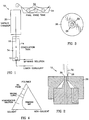
- reference numeral 10 generally indicates apparatus for making a hollow fibre membrane, the apparatus comprising a spinneret 12 for extruding a spinning solution upwardly into a coagulation tank 14 to form a hollow fibre membrane 16.
- the membrane 16 exits the coagulation tank 14 and then enters a high humidity vapour chamber 20. From the vapour chamber 20 it passes around a series of idler rollers 22 through a rinse tank 24.
- the spinneret 12 is of conventional construction and comprises a body 26 which defines an orifice 28, and centrally of the orifice there is a tube 30.
- a membrane-forming polymer solution (also referred to herein as the spinning solution) is injected into a chamber formed around the tube 30. This causes a nascent membrane 32 to be extruded from the annulus between the body 26 and the tube 30.
- a lumen coagulant is injected into the nascent membrane via the tube 30.
- the spinning solution has the following composition:
- the spinning solution is metered through the annulus of the spinneret at a rate of typically 4m/min.
- the outside diameter of the annulus is typically 2,1mm and the inside diameter typically 1,2mm.
- the lumen coagulant may be pure water or water containing fractions of solvent, or organic or inorganic additives, depending on the final internal skin morphology that is required.
- the liquid 34 in the coagulation bath consists of water with a relatively high solvent content.
- the water content should be less than 20% by volume and is typically about 2% by volume.
- the liquid 34 should be at about room temperature, i.e. about 22°C. It has been found that when this is the case the gelation process by which an external skin is normally formed on the outside of the nascent membrane does not take place, as liquid-liquid phase separation is thermodynamically the favoured process.
- the coagulation tank 14 preferably has a height of about 1,2m.
- the membrane 18 After leaving the coagulation tank 14, the membrane 18 passes through the vapour chamber 20 in which there is a highly humid atmosphere.
- the humidity in the chamber 20 should be sufficiently high to induce coagulation of the phase separated polymer, thereby creating a membrane with an open external surface structure.
- the chamber 20 has a height of between 300 and 1200mm, typically 1000mm.
- the relative humidity in the chamber is raised by cascading hot water (at a temperature of typically 40°C) down the inside of the chamber.
- the membrane 16 passes through the rinse tank 24 where solvent is extracted before further processing of the membrane takes place.
- Membranes with unique morphologies can be produced by manipulating and adjusting the various factors that control the wet-phase inversion manufacturing process by which most asymmetric membranes are formed. In this way it is possible to produce low-molecular-mass cut-off ultrafiltration or microfiltration membranes from the same polymer by changing only the polymer concentration and spinning solution solvent system used. Although the final membrane morphology is largely determined by the spinning solution formulation, the fabrication protocol plays an equally important role in controlling the properties and performance of the final membrane structure. By careful adjustment of the membrane spinning solution formulation and fabrication protocol, capillary ultrafiltration membranes were developed for use in a membrane bioreactor.
- the method by which the membranes described were fabricated was based on known wet-phase inversion techniques. The following considerations were used to determine the formulation of the internal and external coagulants, and of the spinning solution.
- Capillary membranes are formed by extruding (spinning) a polymer solution through an annular tube-in-orifice spinneret, by means of a stainless steel precision-gear metering pump. Such a spinneret was positioned at the bottom of the non-solvent coagulation tank, and the membrane was drawn vertically from the spinneret at a rate of 4m/min. Pure water was metered into the lumen of the membrane, so as to form a thin, dense inner skin layer. As the external coagulant was high in solvent content, and the membrane formation by phase-inversion was not completed where the nascent membrane left the coagulant bath, the nascent membrane was then exposed to a non-solvent vapour atmosphere. This completed the process of membrane-formation by phase-inversion, and the membrane could then be transferred to guide rollers in the rinse tanks without damage.
- composition of some of the initial spinning solutions that were examined are given in Table 1.
- the solutions were prepared in 2L resin kettles equipped with a high-speed overhead stirrer, and placed in an oil bath. The solvation temperature was maintained at 60°C. The shaft of the stirrer was passed through a Liebig condenser which prevented loss of low boiling point solvent(s). A minimum period of 48h was required to obtain a homogeneous solution. The solution was then decanted into Schott bottles, rotated slowly for 48h on rollers at ambient temperature, filtered through a 5 ⁇ m stainless-steel filter and degassed in a desiccator for 24h, directly before use.
- the membranes were rinsed in pure water for 24h, and then conditioned in a 1:1 aqueous glycerine solution before they were dried out in a high-humidity chamber at ambient temperature for a period of 7 days.
- the membrane specimens did not undergo thermal or any other form of post-treatment.
- Specimen membranes were fractured at liquid nitrogen temperatures and then sputter-coated with gold at low vacuum ( ⁇ 0,1 torr) in an argon atmosphere and 20mA current, for a period of two minutes.
- the membrane specimens were observed with a Jeol JSM 840 scanning electron microscope (SEM).
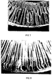
- FIG. 5 shows a micrograph of the cross-section of membrane PSf-1 (see Table 1). A large number of the macrovoids seen in Figure 5 were dead-ended, that is, not extending the full width of the membrane wall.
- Figures 6, 7 and 8 are micrographs of cross-sections of membranes PSf-2, PSf-3 and PSf-4 (see Table 1). It is evident from these Figures 6, 7, and 8 that membrane PSf-4 showed some promise for further development as the macrovoids present in it were narrow and their spacing strikingly regular. The macrovoids of the membrane shown in Figure 8 were also fully developed and open-ended, few appearing not to extend the full width of the membrane.
- the aqueous contents of the external coagulant had to be reduced considerably, below the 20% level, to prevent gelation, nucleation or phase-separation by any of the various mechanisms that are responsible for this.
- the lower limit of the aqueous content of the external bath was that point at which the coagulant actually started to re-dissolve the nascent membrane.
- 50g of membrane PSf-5 spinning solution (see Table 2) was shaken up with an equal amount of aqueous solvent mixture at 22°C.
- the spinning solution dissolved without any sign of cloudiness in aqueous mixtures containing up to 8% water, although dissolution of the spinning solution became progressively slower at higher water contents.
- the first sign of cloudiness appeared at water concentration levels of 9% and greater. It was therefore reasoned that a water concentration level of 9% should be regarded as the preferred upper aqueous limit of the external coagulant bath.
- the next step in the development of the bioreactor membrane was to spin the polysulphone membranes into external coagulants that contained less water than the proposed 9% upper limit.
- Table 3 shows the water content of three of the solvent coagulation baths that were used. The compositions of each of the three coagulation baths had a pronounced effect on the exterior morphology of the membrane.
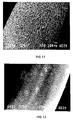
- Figures 10, 11 and 12 show the external surface textures of the respective membranes, and give a clear indication of the pronounced effect of decreasing the water content.
- the outer regions of the membrane seemed to re-dissolve (and smudge), to form a secondary skin layer of low definition (see Figure 10 and 11).
- Gelation occurred and skin morphologies similar to that shown in Figure 9 again become prominent.
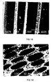
- FIG 13 shows a cross-section of membrane PSf-5, which was cast into a 7,9% aqueous solvent coagulation bath.
- the ultrafiltration membrane had a well-defined internal skin layer and the spacing of the open-ended narrow-bore macrovoids which radiated from the internal skin layer was strikingly regular. It was clear from the micrograph that coagulation was initiated from the lumen side. Formation of solvent-rich nuclei below the skin layer was possibly enhanced by the controlled tension under which the membrane was drawn away from the spinneret.
- Shrinkage (the outside diameter of the spinneret was 2,1mm, whereas the final membrane diameter was 1,8mm) may have played a role in sustaining the exchange of non-solvent and growth of the finger-like cavities across substantially the full width of the membrane.
- the composition of the external coagulant fell just outside the demixing gap on the ternary phase diagram (see Figure 4) and did not affect the state of the nascent membrane with which it was in contact. It was found desirable for the solvent content of the external coagulant to be within 5% of the point where the binodal curve intersects the solvent-non-solvent axis.
- Surface tension within the polymer-rich phase maintained the structural integrity of the soft, viscous, coagulated, polymer-rich phase until it was finally set when brought into contact with the non-solvent vapour in the vapour chamber.
- FIG 14 again shows membrane PSf-5 and the striking uniformity of the macrocells which, as shown in Figure 15, had highly porous walls.
- the average diameter of the macrovoids was 20 ⁇ m (see Figure 16). From the micrographs the diameter of the membrane was calculated to be 1,8mm and the diameter of the macrovoid openings 25 ⁇ m (i.e. the diameter of the macrovoids plus one times the thickness of the walls defining them). Based on these calculations, it was estimated that there were more than 9x10 6 macrovoids per metre-length of membrane.
- Membranes were prepared from polyethersulphone by the same method, although with minor modifications to the fabrication protocol.
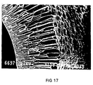
- a cross-section of membrane PES-1 is shown in Figure 17. This shows that the morphology of the macrovoids of the polyethersulphone membrane was different to those of the polysulphone membranes.
- the spinning solution formulations and fabrication protocol were, except for the composition of the external coagulation bath, identical for both membranes, the difference in morphologies could possibly be ascribed in the different coagulation pathways and glass-transition points that exist for the two polymer systems .
- Initial results also indicated that many of the macrovoids in the polyethersulphone membrane were dead-ended, and therefore not nearly as regular as those of membrane PSf-5.
- an internally skinned membrane with narrow-bore macrovoids extending substantially the full width of the membrane and with no external skin layer can consistently be produced from at least polysulphone and polyethersulphone.
- the membranes have good mechanical strength and unique morphological properties, which make them useful for biotechnological and filtration separation applications.
- the membrane formation process of the present invention may also be used to produce a membrane from polymers that have been modified to incorporate ligands onto which enzymes may covalently be bonded.
- a typical example is polyacrylonicrile-co-maleic anhydride or polymer materials that will result in membranes with fixed surface charges.
- Spinning solution formulations to produce membranes with finger-like macrovoids in substructure Component Membrane code PSf-1 PSf-2 PSf-3 PSf-4 Mass percent Ultrason S (PSf) 26 24 24 24 24 24 24 24 24 24 24 24 24 24 24 24 24 24 24 24 24 24 24 24 24 24 24 24 24 24 24 24 24 24 24 24 24 24 24 24 24 24 24 24 24 24 24 24 24 24 24 24 24 24 24 24 24 24 24 24 24 24 24 24 24 24 24 24 24 24 24 24 24 24 24 24 24 24 24 24 24 24 24 24 24 24 24 24 24 24 24 24 24 24 24 24 24 24 24 24 24 24 24 24 24 24 24 24 24 24 24 24 24 24 24 24 24 24 24 24 24 24 24 24 24 24 24 24 24 High boiling
Landscapes
- Chemical & Material Sciences (AREA)
- Engineering & Computer Science (AREA)
- Genetics & Genomics (AREA)
- Wood Science & Technology (AREA)
- Health & Medical Sciences (AREA)
- Life Sciences & Earth Sciences (AREA)
- Bioinformatics & Cheminformatics (AREA)
- Organic Chemistry (AREA)
- Zoology (AREA)
- Chemical Kinetics & Catalysis (AREA)
- Biomedical Technology (AREA)
- Microbiology (AREA)
- Biotechnology (AREA)
- Biochemistry (AREA)
- General Engineering & Computer Science (AREA)
- General Health & Medical Sciences (AREA)
- Dispersion Chemistry (AREA)
- Manufacturing & Machinery (AREA)
- Mechanical Engineering (AREA)
- Textile Engineering (AREA)
- Separation Using Semi-Permeable Membranes (AREA)
- Artificial Filaments (AREA)
- Spinning Methods And Devices For Manufacturing Artificial Fibers (AREA)
Abstract
Description
- THIS INVENTION relates to a method of making a hollow fibre membrane, particularly for use in membrane separation processes and membrane bioreactor applications.
- According to the invention there is provided a method of making a hollow fibre membrane in which a membrane-forming polymer solution is extruded through the annulus of a tube-in-orifice spinneret to form a nascent hollow membrane, there being a lumen coagulant in the lumen of the nascent membrane, the lumen coagulant having a high non-solvent content so as to form the membrane with an internal skin by gelation of the polymer solution on the inside of the nascent membrane and the outside of the nascent membrane being contacted with an external coagulant, wherein the external coagulant has a solvent content which is such that, at the interface between the nascent membrane and the external coagulant, liquid-liquid phase separation rather than gelation is thermodynamically the favoured process, and wherein the membrane is then subjected to a vapour-phase non-solvent environment to induce precipitation of the phase-separated polymer.
- The external coagulant may have a solvent content which is such that, in a phase diagram of the ternary system consisting of the solvent component of the coagulant, the non-solvent component of the coagulant, and the polymer, and having a solvent-non-solvent axis, a demixing gap, and a binodal curve at the boundary of the demixing gap, the composition of the external coagulant lies within 5% of the point where the binodal curve intersects the solvent-non-solvent axis.
- In another aspect of the invention the external coagulant may have a solvent content which is such that, in a phase diagram of the ternary system consisting of the solvent component of the coagulant, the non-solvent component of the coagulant, and the polymer, and having a solvent-non-solvent axis, a demixing gap, and a binodal curve at the boundary of the demixing gap, the composition of the external coagulant lies outside the demixing gap.
- The external coagulant may be a solution of polymer solvent in water.
- The water content of the external coagulant may be less than 20% by volume, and preferably less than 9% by volume. In particular, the water content of the external coagulant may be about 2% by volume.
- The vapour of the non-solvent vapour phase environment may be water vapour.
- The polymer of the membrane-forming polymer solution may be polysulphone or polyethersulphone.
- The invention will now be described in more detail, by way of example, with reference to the accompanying drawings.
- In the drawings:
- Figure 1 diagrammatically illustrates apparatus for making a hollow fibre membrane in accordance with the invention;
- Figure 2 is a vertical section through a spinneret used in the apparatus;
- Figure 3 is a plan view of the spinneret;
- Figure 4 is a ternary phase diagram of the polymer solvent system;
- Figure 5 is an electron micrograph of a cross-section of membrane PSf-1;
- Figure 6 is an electron micrograph of a cross-section of membrane PSf-2;
- Figure 7 is an electron micrograph of a cross-section of membrane PSf-3;
- Figure 8 is an electron micrograph of a cross-section of membrane PSf-4;
- Figure 9 is an electron micrograph showing the external skin-surface of a polysulphone membrane coagulated in a 20% aqueous solvent coagulant;
- Figure 10 is an electron micrograph showing the external surface of membrane PSf-5/1 cast into a 4,3% aqueous solvent coagulant;
- Figure 11 is an electron micrograph showing the external surface of membrane PSf-5/2 cast into a 6,1% aqueous solvent coagulant;
- Figure 12 is an electron micrograph showing the external surface of membrane PSf-5/3 cast into a 7,9% aqueous solvent coagulant;
- Figure 13 is an electron micrograph showing a cross-section of membrane PSf-5/3;
- Figure 14 is an electron micrograph showing the finger-like macrovoids of membrane PSf-5/3;
- Figure 15 is an electron micrograph showing a close-up of the macrovoids of membrane PSf-5/3, to reveal the macroporous morphology of the macrovoid walls;
- Figure 16 is an electron micrograph showing a close-up of the exterior surface of membrane PS-5/3; and
- Figure 17 is an electron micrograph showing a cross-section of polyethersulphone membrane PES-1.
-
- The Tables referred to in the description appear at the end of the description.
- Referring first to Figures 1 to 3,
reference numeral 10 generally indicates apparatus for making a hollow fibre membrane, the apparatus comprising aspinneret 12 for extruding a spinning solution upwardly into acoagulation tank 14 to form ahollow fibre membrane 16. Themembrane 16 exits thecoagulation tank 14 and then enters a highhumidity vapour chamber 20. From thevapour chamber 20 it passes around a series ofidler rollers 22 through arinse tank 24. - The
spinneret 12 is of conventional construction and comprises abody 26 which defines anorifice 28, and centrally of the orifice there is atube 30. A membrane-forming polymer solution (also referred to herein as the spinning solution) is injected into a chamber formed around thetube 30. This causes anascent membrane 32 to be extruded from the annulus between thebody 26 and thetube 30. A lumen coagulant is injected into the nascent membrane via thetube 30. - In a preferred embodiment of the invention the spinning solution has the following composition:
- 1. Polymer resin in the form of polysulphone (PSf) or polyethersulphone (PES). The higher the concentration of the polymer resin, the higher the density of the skin structure of the resultant fibre membrane. The upper limit of the concentration is determined by porosity (or density) of the substructure or skin that is required. If the concentration of the polymer resin is too low, the fibre membrane loses its mechanical integrity. A concentration of between 18 and 28m/m% has been found to give good results.
- 2. A polymer additive in the form of polyethylene glycol (PEG600), at a concentration of between 10 and 35m/m%.
- 3. A true solvent in the form of N-methyl, 2-pyrrolidine (NMP). Alternatively other aprotic solvents such as N,N-dimethylacetamide (DMAc) or N,N-dimethylformamide may be used.
- 4. A non-solvent additive in the form of methyl Cellusolve (MC), at a concentration of between 0 and 20m/m%. A formulation that has been found to give good results consisted of
-
- The
nascent membrane 32 with the non-solvent coagulant in the lumen thereof rises in a bath ofexternal coagulant 34 in thecoagulation tank 14. - The spinning solution is metered through the annulus of the spinneret at a rate of typically 4m/min. The outside diameter of the annulus is typically 2,1mm and the inside diameter typically 1,2mm.
- The lumen coagulant may be pure water or water containing fractions of solvent, or organic or inorganic additives, depending on the final internal skin morphology that is required.
- The
liquid 34 in the coagulation bath consists of water with a relatively high solvent content. The water content should be less than 20% by volume and is typically about 2% by volume. Theliquid 34 should be at about room temperature, i.e. about 22°C. It has been found that when this is the case the gelation process by which an external skin is normally formed on the outside of the nascent membrane does not take place, as liquid-liquid phase separation is thermodynamically the favoured process. - Gelation does, however, take place on the inside of the membrane, due to the high non-solvent content of the lumen coagulant.
- Nucleation and growth of respectively polymer-poor and polymer-rich phases follows and the macro- and micro-structure of the membrane is determined. The polymer in the outer regions of the membrane does not precipitate due to the high concentration of solvent in the
coagulation tank 14. Thecoagulation tank 14 preferably has a height of about 1,2m. - After leaving the
coagulation tank 14, the membrane 18 passes through thevapour chamber 20 in which there is a highly humid atmosphere. The humidity in thechamber 20 should be sufficiently high to induce coagulation of the phase separated polymer, thereby creating a membrane with an open external surface structure. Thechamber 20 has a height of between 300 and 1200mm, typically 1000mm. The relative humidity in the chamber is raised by cascading hot water (at a temperature of typically 40°C) down the inside of the chamber. - From the
chamber 20 themembrane 16 passes through the rinsetank 24 where solvent is extracted before further processing of the membrane takes place. - It is important for the membrane to be drawn from the
spinneret 12 with as little tension as possible. Too much tension leads to the formation of micro-cracks in the internal skin layer, which in turn leads to leaking of the lumen coagulant and destruction of the external surface structure of the membrane. - Membranes with unique morphologies can be produced by manipulating and adjusting the various factors that control the wet-phase inversion manufacturing process by which most asymmetric membranes are formed. In this way it is possible to produce low-molecular-mass cut-off ultrafiltration or microfiltration membranes from the same polymer by changing only the polymer concentration and spinning solution solvent system used. Although the final membrane morphology is largely determined by the spinning solution formulation, the fabrication protocol plays an equally important role in controlling the properties and performance of the final membrane structure. By careful adjustment of the membrane spinning solution formulation and fabrication protocol, capillary ultrafiltration membranes were developed for use in a membrane bioreactor.
- It is known that delayed precipitation leads to the formation of Type I membranes which nearly always exhibit sponge-like structures with dense skin layers. Conversely, instantaneous or rapid precipitation leads to the formation of Type II membranes which are often thin-skinned with finger-like macrovoids in the sub-layers. The following generalisations apply to the formulation of spinning solutions for the formation of Type II membrane:
- strong non-solvents (e.g. water) increase the miscibility gap in the ternary phase diagram and favour composition profiles that support rapid phase separation;
- low initial polymer concentration will favour the formation of membranes with thin open-porous skin layers and macrovoids;
- small additions of non-solvent additive(s) to the spinning solution will favour the formation of thin-skinned membranes with macrovoids; and
- addition of high solvent concentrations to the coagulation medium will favour the formation of low-density and thinner skin layers, with sponge-like sub-layers.
- Some experimental work that was done is described in what follows.
- The method by which the membranes described were fabricated was based on known wet-phase inversion techniques. The following considerations were used to determine the formulation of the internal and external coagulants, and of the spinning solution.
- Skin-formation, i.e. gelation, on the lumen side generally results from contact with a strong non-solvent. Pure water with no solvent or other additives was therefore used as the internal coagulant to generate a thin-skinned membrane.
- The formation of macrovoids arises from the nucleation and rapid growth of polymer-poor nuclei. In the fabrication of conventional hollow fibre membranes, measures are often taken to suppress the formation of macrovoids. To achieve the objects of the present invention, however, the formation of solvent-rich nuclei had to be stimulated, and the solvent composition of the spinning solution and of the external coagulant chosen to sustain growth of the macrovoid from just below the skin layer all the way to the membrane exterior.
- To form an open-pore surface on the outside of the membrane, gelation on contact with the external coagulant bath had to be suppressed. Gelation (skin-formation) can be suppressed and liquid-liquid phase separation thermodynamically favoured if the coagulant bath contains low concentrations of non-solvent. If the composition of the external coagulant bath reflects that of the polymer-poor phase front as it nears the membrane exterior, there should be no driving force for diffusion (i.e. no concentration gradient) and the phase-inversion process should therefore cease. As a first approach, the composition of the external coagulation bath was selected to have a solvent/nonsolvent ratio close to the cloud-point of the spinning solution. A 20% aqueous of solution of NMP was chosen as starting point.
- Capillary membranes are formed by extruding (spinning) a polymer solution through an annular tube-in-orifice spinneret, by means of a stainless steel precision-gear metering pump. Such a spinneret was positioned at the bottom of the non-solvent coagulation tank, and the membrane was drawn vertically from the spinneret at a rate of 4m/min. Pure water was metered into the lumen of the membrane, so as to form a thin, dense inner skin layer. As the external coagulant was high in solvent content, and the membrane formation by phase-inversion was not completed where the nascent membrane left the coagulant bath, the nascent membrane was then exposed to a non-solvent vapour atmosphere. This completed the process of membrane-formation by phase-inversion, and the membrane could then be transferred to guide rollers in the rinse tanks without damage.
- Grade 3010 Ultrason S (polysulphone) and Ultrason E (polyethersulphone) from BASF were used as the polymer, NMP as the solvent, and MC as the non-solvent in the spinning solution. The solvent and non-solvent(s) were vacuum distilled in an inert atmosphere and stored over a 3Å molecular sieve. A chemically pure, low molecular mass (liquid) polymer additive in the form of PEG600, and an industrial grade, high molecular mass polymer additive in the form of polyvinylpyrrolidone K30 (PVP) were used.
- The composition of some of the initial spinning solutions that were examined are given in Table 1. The solutions were prepared in 2L resin kettles equipped with a high-speed overhead stirrer, and placed in an oil bath. The solvation temperature was maintained at 60°C. The shaft of the stirrer was passed through a Liebig condenser which prevented loss of low boiling point solvent(s). A minimum period of 48h was required to obtain a homogeneous solution. The solution was then decanted into Schott bottles, rotated slowly for 48h on rollers at ambient temperature, filtered through a 5µm stainless-steel filter and degassed in a desiccator for 24h, directly before use.
- After fabrication, the membranes were rinsed in pure water for 24h, and then conditioned in a 1:1 aqueous glycerine solution before they were dried out in a high-humidity chamber at ambient temperature for a period of 7 days. The membrane specimens did not undergo thermal or any other form of post-treatment.
- Specimen membranes were fractured at liquid nitrogen temperatures and then sputter-coated with gold at low vacuum (<0,1 torr) in an argon atmosphere and 20mA current, for a period of two minutes. The membrane specimens were observed with a Jeol JSM 840 scanning electron microscope (SEM).
- As a first approach the membranes were spun into an aqueous external coagulation bath with a solvent content of 80%, using the same solvent as that used in the spinning solution. Figure 5 shows a micrograph of the cross-section of membrane PSf-1 (see Table 1). A large number of the macrovoids seen in Figure 5 were dead-ended, that is, not extending the full width of the membrane wall. Figures 6, 7 and 8 are micrographs of cross-sections of membranes PSf-2, PSf-3 and PSf-4 (see Table 1). It is evident from these Figures 6, 7, and 8 that membrane PSf-4 showed some promise for further development as the macrovoids present in it were narrow and their spacing strikingly regular. The macrovoids of the membrane shown in Figure 8 were also fully developed and open-ended, few appearing not to extend the full width of the membrane.
- Although some of the features of membrane PSf-4 were what was required, the membrane shown in Figure 8 still required further modification. It appeared from the micrograph of Figure 8 that the wall on the lumen side of this membrane was skinned and not microporous. The spinning solution therefore had to be modified further to promote greater porosity, as this was thought to be necessary for the membrane to be effective for use in a bioreactor. The formulation was adjusted by decreasing the polysulphone concentration and increasing the low molecular mass polymer additive concentration. The resultant formulation (PSf-5), which was subsequently used in all further experiments, is given in Table 2.
- It proved difficult to prevent the formation of a skin layer on the outside of the membrane. In Figure 5 an external skin layer is clearly visible in the micrograph, even though the external coagulant was high in solvent content and therefore had little precipitation potential. However, not all membranes which coagulated in the 20% aqueous solvent had well-defined external skin layers, as regularly spaced cavities were prominent in some of the membranes (see Figure 9).
- If earlier assumptions regarding skin-formation were correct, the aqueous contents of the external coagulant had to be reduced considerably, below the 20% level, to prevent gelation, nucleation or phase-separation by any of the various mechanisms that are responsible for this. However, the lower limit of the aqueous content of the external bath was that point at which the coagulant actually started to re-dissolve the nascent membrane. To determine this point, 50g of membrane PSf-5 spinning solution (see Table 2) was shaken up with an equal amount of aqueous solvent mixture at 22°C. The spinning solution dissolved without any sign of cloudiness in aqueous mixtures containing up to 8% water, although dissolution of the spinning solution became progressively slower at higher water contents. The first sign of cloudiness appeared at water concentration levels of 9% and greater. It was therefore reasoned that a water concentration level of 9% should be regarded as the preferred upper aqueous limit of the external coagulant bath.
- The next step in the development of the bioreactor membrane was to spin the polysulphone membranes into external coagulants that contained less water than the proposed 9% upper limit. Table 3 shows the water content of three of the solvent coagulation baths that were used. The compositions of each of the three coagulation baths had a pronounced effect on the exterior morphology of the membrane. Figures 10, 11 and 12 show the external surface textures of the respective membranes, and give a clear indication of the pronounced effect of decreasing the water content. In external coagulants with a low aqueous content the outer regions of the membrane seemed to re-dissolve (and smudge), to form a secondary skin layer of low definition (see Figure 10 and 11). At higher water concentrations gelation occurred and skin morphologies similar to that shown in Figure 9 again become prominent.
- Figure 13 shows a cross-section of membrane PSf-5, which was cast into a 7,9% aqueous solvent coagulation bath. The ultrafiltration membrane had a well-defined internal skin layer and the spacing of the open-ended narrow-bore macrovoids which radiated from the internal skin layer was strikingly regular. It was clear from the micrograph that coagulation was initiated from the lumen side. Formation of solvent-rich nuclei below the skin layer was possibly enhanced by the controlled tension under which the membrane was drawn away from the spinneret.
- Shrinkage (the outside diameter of the spinneret was 2,1mm, whereas the final membrane diameter was 1,8mm) may have played a role in sustaining the exchange of non-solvent and growth of the finger-like cavities across substantially the full width of the membrane. The composition of the external coagulant fell just outside the demixing gap on the ternary phase diagram (see Figure 4) and did not affect the state of the nascent membrane with which it was in contact. It was found desirable for the solvent content of the external coagulant to be within 5% of the point where the binodal curve intersects the solvent-non-solvent axis. Surface tension within the polymer-rich phase maintained the structural integrity of the soft, viscous, coagulated, polymer-rich phase until it was finally set when brought into contact with the non-solvent vapour in the vapour chamber.
- Figure 14 again shows membrane PSf-5 and the striking uniformity of the macrocells which, as shown in Figure 15, had highly porous walls. The average diameter of the macrovoids was 20µm (see Figure 16). From the micrographs the diameter of the membrane was calculated to be 1,8mm and the diameter of the macrovoid openings 25µm (i.e. the diameter of the macrovoids plus one times the thickness of the walls defining them). Based on these calculations, it was estimated that there were more than 9x10⁶ macrovoids per metre-length of membrane.
- It is commonly observed that the presence of macrovoids in the substructure of membranes does not always benefit the mechanical integrity of the membrane. In the present case it was important to reduce the thickness of the internal skin layer to stimulate macrovoid formation and maximize the void length. Because of the resultant reduction in support provided by the skin layer, the membrane resistance and hence the hydrostatic driving force that the membrane can sustain were also reduced. The membranes were nonetheless reasonably robust with instantaneous burst-pressures ranging from 2,3MPa for membrane PSf-1 to 1,8MPa for membrane PSf-5.
- Membranes were prepared from polyethersulphone by the same method, although with minor modifications to the fabrication protocol. A cross-section of membrane PES-1 is shown in Figure 17. This shows that the morphology of the macrovoids of the polyethersulphone membrane was different to those of the polysulphone membranes. As the spinning solution formulations and fabrication protocol were, except for the composition of the external coagulation bath, identical for both membranes, the difference in morphologies could possibly be ascribed in the different coagulation pathways and glass-transition points that exist for the two polymer systems . Initial results also indicated that many of the macrovoids in the polyethersulphone membrane were dead-ended, and therefore not nearly as regular as those of membrane PSf-5.
- It has thus been shown that an internally skinned membrane with narrow-bore macrovoids extending substantially the full width of the membrane and with no external skin layer can consistently be produced from at least polysulphone and polyethersulphone. The membranes have good mechanical strength and unique morphological properties, which make them useful for biotechnological and filtration separation applications.
- The membrane formation process of the present invention may also be used to produce a membrane from polymers that have been modified to incorporate ligands onto which enzymes may covalently be bonded. A typical example is polyacrylonicrile-co-maleic anhydride or polymer materials that will result in membranes with fixed surface charges.
Spinning solution formulations to produce membranes with finger-like macrovoids in substructure Component Membrane code PSf-1 PSf-2 PSf-3 PSf-4 Mass percent Ultrason S (PSf) 26 24 24 24 High boiling point solvent (NMP) 51 46 56 36 Low boiling point non-solvent additive (MC) 2 10 10 10 Low molecular mass polymer additive (PEG600) 11 10 30 High molecular mass polymer additive (PVP) 10 10 10 - All the spinning solutions have unlimited shelf-life if the starting materials are dry
Modified spinning solution formulations to enhance porosity Component Membrane code PSf-5 PES-1 Mass percent Ultrason S (PSf) 22 Ultrason E (PES) 22 High boiling point solvent (NMP) 36 36 Low boiling point non-solvent additive (MC) 10 10 High molecular mass polymer additive (PVP) 32 32 Water content of aqueous solvent external coagulation bath Membrane code Water content Mass percent PSf-5/1 4,3 PSf-5/2 6,1 PSf-5/3 7,9 - Water content determined by Karl Fischer titration
Claims (13)
- A method of making a hollow fibre membrane in which a membrane-forming polymer solution is extruded through the annulus of a tube-in-orifice spinneret to form a nascent hollow membrane, there being a lumen coagulant in the lumen of the nascent membrane, the lumen coagulant having a high non-solvent content so as to form the membrane with an internal skin by gelation of the polymer solution on the inside of the nascent membrane, and the outside of the nascent membrane being contacted with an external coagulant (34), characterised in that the external coagulant (34) has a solvent content which is such that, at the interface between the nascent membrane and the external coagulant, liquid-liquid phase separation rather than gelation is thermodynamically the favoured process, and in that the membrane is then subjected to a vapour-phase non-solvent environment to induce precipitation of the phase-separated polymer.
- A method as claimed in claim 1, characterised in that the external coagulant (34) has a solvent content which is such that, in a phase diagram of the ternary system consisting of the solvent component of the coagulant, the non-solvent component of the coagulant, and the polymer, and having a solvent-non-solvent axis, a demixing gap, and a binodal curve at the boundary of the demixing gap, the composition of the external coagulant lies within 5% of the point where the binodal curve intersects the solvent-non-solvent axis.
- A method as claimed in claim 1, characterised in that the external coagulant (34) has a solvent content which is such that, in a phase diagram of the ternary system consisting of the solvent component of the coagulant, the non-solvent component of the coagulant, and the polymer, and having a solvent-non-solvent axis, a demixing gap, and a binodal curve at the boundary of the demixing gap, the composition of the external coagulant lies outside the demixing gap.
- A method as claimed in claim 3, characterised in that the solvent content of the external coagulant (34) is such that the composition thereof lies within 5% of the point where the binodal curve intersects the solvent-non-solvent axis.
- A method as claimed in any one of the preceding claims, characterised in that the external coagulant (34) is a solution of polymer solvent in water.
- A method as claimed in claim 5, characterised in that the water content of the external coagulant (34) is less than 20% by volume.
- A method as claimed in claim 5, characterised in that the water content of the external coagulant (34) is less than 9% by volume.
- A method as claimed in claim 7, characterised in that the water content of the external coagulant (34) is about 2% by volume.
- A method as claimed in any one of the preceding claims, characterised in that the vapour of the non-solvent vapour phase environment is water vapour.
- A method as claimed in any one of the preceding claims, characterised in that the polymer of the membrane-forming polymer solution is polysulphone.
- A method as claimed in any one of claims 1 to 9, characterised in that the polymer of the membrane-forming polymer solution is polyethersulphone.
- A method as claimed in any one of claims 1 to 9, characterised in that the membrane-forming polymer incorporates ligands onto which enzymes can be covalently bonded.
- A method as claimed in claim 12, characterised in that the membrane-forming polymer is polyacrylonitrile-co-maleic anhydride or a polymer material that will result in a membrane with fixed surface charges.
Applications Claiming Priority (2)
| Application Number | Priority Date | Filing Date | Title |
|---|---|---|---|
| ZA954648 | 1995-06-06 | ||
| ZA9504648 | 1995-06-06 |
Publications (3)
| Publication Number | Publication Date |
|---|---|
| EP0747112A2 EP0747112A2 (en) | 1996-12-11 |
| EP0747112A3 EP0747112A3 (en) | 1997-10-22 |
| EP0747112B1 true EP0747112B1 (en) | 2002-01-16 |
Family
ID=25585133
Family Applications (1)
| Application Number | Title | Priority Date | Filing Date |
|---|---|---|---|
| EP96304167A Expired - Lifetime EP0747112B1 (en) | 1995-06-06 | 1996-06-06 | Method of making a hollow fibre membrane |
Country Status (4)
| Country | Link |
|---|---|
| US (1) | US5833896A (en) |
| EP (1) | EP0747112B1 (en) |
| AT (1) | ATE211944T1 (en) |
| DE (1) | DE69618500D1 (en) |
Cited By (2)
| Publication number | Priority date | Publication date | Assignee | Title |
|---|---|---|---|---|
| CN103114343A (en) * | 2013-03-01 | 2013-05-22 | 天津工业大学 | Spinneret plate assembly for manufacturing nineteen-channel hollow fiber membrane |
| CN112672813A (en) * | 2019-02-28 | 2021-04-16 | 东洋纺株式会社 | Hollow fiber membrane and method for producing hollow fiber membrane |
Families Citing this family (19)
| Publication number | Priority date | Publication date | Assignee | Title |
|---|---|---|---|---|
| US6890435B2 (en) * | 2002-01-28 | 2005-05-10 | Koch Membrane Systems | Hollow fiber microfiltration membranes and a method of making these membranes |
| US7951449B2 (en) | 2002-06-27 | 2011-05-31 | Wenguang Ma | Polyester core materials and structural sandwich composites thereof |
| US20040194130A1 (en) * | 2003-03-07 | 2004-09-30 | Richard Konig | Method and system for advertisement detection and subsitution |
| US6826342B1 (en) | 2003-03-13 | 2004-11-30 | Fitel U.S.A. Corp. | Temperature tuning of dispersion in photonic band gap fiber |
| US6939392B2 (en) | 2003-04-04 | 2005-09-06 | United Technologies Corporation | System and method for thermal management |
| US7440664B2 (en) * | 2003-04-08 | 2008-10-21 | Fitel Usa Corp. | Microstructured optical waveguide for providing periodic and resonant structures |
| WO2007004170A2 (en) * | 2005-06-30 | 2007-01-11 | Synexa Life Sciences (Proprietary) Limited | Production of secondary metabolites using capillary membranes |
| US7897048B2 (en) * | 2005-11-17 | 2011-03-01 | Australian Nuclear Science And Technology Organisation | Membrane bioreactor and sewage treatment method |
| US9821105B2 (en) | 2008-07-01 | 2017-11-21 | Baxter International Inc. | Nanoclay sorbents for dialysis |
| WO2015153370A2 (en) | 2014-03-29 | 2015-10-08 | Labib Mohamed E | Blood processing cartridges and systems, and methods for extracorporeal blood therapies |
| US10426884B2 (en) | 2015-06-26 | 2019-10-01 | Novaflux Inc. | Cartridges and systems for outside-in flow in membrane-based therapies |
| US10399040B2 (en) | 2015-09-24 | 2019-09-03 | Novaflux Inc. | Cartridges and systems for membrane-based therapies |
| RU2652212C1 (en) * | 2017-03-13 | 2018-04-25 | Общество с ограниченной ответственностью "ТЕКОН МЕМБРАННЫЕ ТЕХНОЛОГИИ" | Hollow fiber membrane |
| US10889915B2 (en) | 2018-01-31 | 2021-01-12 | Saudi Arabian Oil Company | Producing fibers using spinnerets |
| RU2676991C1 (en) * | 2018-05-07 | 2019-01-14 | Общество с ограниченной ответственностью "ТЕКОН МЕМБРАННЫЕ ТЕХНОЛОГИИ" | Hollow fiber membrane |
| CN112226829B (en) * | 2019-07-15 | 2022-04-05 | 中国石油化工股份有限公司 | Preparation method of high-strength polyacrylonitrile precursor |
| US11406941B2 (en) | 2020-02-14 | 2022-08-09 | Saudi Arabian Oil Company | Thin film composite hollow fiber membranes fabrication systems |
| US11253819B2 (en) | 2020-05-14 | 2022-02-22 | Saudi Arabian Oil Company | Production of thin film composite hollow fiber membranes |
| US12116326B2 (en) | 2021-11-22 | 2024-10-15 | Saudi Arabian Oil Company | Conversion of hydrogen sulfide and carbon dioxide into hydrocarbons using non-thermal plasma and a catalyst |
Family Cites Families (13)
| Publication number | Priority date | Publication date | Assignee | Title |
|---|---|---|---|---|
| DE260868C (en) * | ||||
| US4181694A (en) * | 1972-04-28 | 1980-01-01 | Asahi Kasei Kogyo Kabushiki Kaisha | Method for producing hollow fibers of acrylonitrile polymers for ultrafilter |
| US3975478A (en) * | 1974-08-14 | 1976-08-17 | Monsanto Company | Method for producing highly permeable acrylic hollow fibers |
| CA1236956A (en) * | 1983-05-02 | 1988-05-24 | Seiichi Manabe | Porous cuprammonium cellulose fibre produced with annular orifice and central coagulating stream |
| US4906375A (en) * | 1984-07-14 | 1990-03-06 | Fresenius, Ag | Asymmetrical microporous hollow fiber for hemodialysis |
| EP0246752B1 (en) * | 1986-05-16 | 1992-03-11 | Imperial Chemical Industries Plc | Fibres and hollow fibrous tubes |
| IT1190137B (en) * | 1986-06-20 | 1988-02-10 | Eniricerche Spa | FIBER, POLYESTER AMID QUARRY AND PROCEDURE FOR ITS PREPARATION |
| DD260868A1 (en) * | 1987-06-26 | 1988-10-12 | Akad Wissenschaften Ddr | METHOD FOR PRODUCING ASYMMETRIC HOLLOW MEMBERS FROM ACRYLIC NITRILE POLYMERIZES |
| US5071917A (en) * | 1988-07-22 | 1991-12-10 | The Dow Chemical Company | High strength fibers of stereoregular polystrene |
| US4970034A (en) * | 1988-09-23 | 1990-11-13 | W. R. Grace & Co.-Conn. | Process for preparing isotropic microporous polysulfone membranes |
| GB8920990D0 (en) * | 1989-09-15 | 1989-11-01 | British Petroleum Co Plc | Membrane fabrication |
| US5151227A (en) * | 1991-03-18 | 1992-09-29 | W. R. Grace & Co.-Conn. | Process for continuous spinning of hollow-fiber membranes using a solvent mixture as a precipitation medium |
| US5181940A (en) * | 1991-08-01 | 1993-01-26 | Union Carbide Industrial Gases Technology Corporation | Hollow fiber membranes |
-
1996
- 1996-06-06 US US08/659,744 patent/US5833896A/en not_active Expired - Lifetime
- 1996-06-06 AT AT96304167T patent/ATE211944T1/en not_active IP Right Cessation
- 1996-06-06 EP EP96304167A patent/EP0747112B1/en not_active Expired - Lifetime
- 1996-06-06 DE DE69618500T patent/DE69618500D1/en not_active Expired - Lifetime
Cited By (3)
| Publication number | Priority date | Publication date | Assignee | Title |
|---|---|---|---|---|
| CN103114343A (en) * | 2013-03-01 | 2013-05-22 | 天津工业大学 | Spinneret plate assembly for manufacturing nineteen-channel hollow fiber membrane |
| CN112672813A (en) * | 2019-02-28 | 2021-04-16 | 东洋纺株式会社 | Hollow fiber membrane and method for producing hollow fiber membrane |
| US12048898B2 (en) | 2019-02-28 | 2024-07-30 | Toyobo Mc Corporation | Hollow fiber membrane and method for producing hollow fiber membrane |
Also Published As
| Publication number | Publication date |
|---|---|
| EP0747112A2 (en) | 1996-12-11 |
| ATE211944T1 (en) | 2002-02-15 |
| EP0747112A3 (en) | 1997-10-22 |
| DE69618500D1 (en) | 2002-02-21 |
| US5833896A (en) | 1998-11-10 |
Similar Documents
| Publication | Publication Date | Title |
|---|---|---|
| EP0747112B1 (en) | Method of making a hollow fibre membrane | |
| Gao et al. | Controllable transition from finger-like pores to inter-connected pores of PLLA membranes | |
| Qin et al. | A high flux ultrafiltration membrane spun from PSU/PVP (K90)/DMF/1, 2-propanediol | |
| Peng et al. | Macrovoid evolution and critical factors to form macrovoid-free hollow fiber membranes | |
| Qin et al. | Cellulose acetate hollow fiber ultrafiltration membranes made from CA/PVP 360 K/NMP/water | |
| Setiawan et al. | Explorations of delamination and irregular structure in poly (amide-imide)-polyethersulfone dual layer hollow fiber membranes | |
| Chou et al. | Effect of molecular weight and concentration of PEG additives on morphology and permeation performance of cellulose acetate hollow fibers | |
| US5049276A (en) | Hollow fiber membrane | |
| US20080210624A1 (en) | The Preparation Method Of Exo-Pressure Type Poly(Vinylidene Fluoride) Hollow Fiber Membrane Spinned Utilizing A Immersion-Coagulation Method And The Product Thereof | |
| JPH0122003B2 (en) | ||
| JPH05212255A (en) | Hollow fiber membrane | |
| US9393530B2 (en) | Process for production of porous membrane | |
| KR20100114808A (en) | Method for asymmetric microporous hollow fiber membrane | |
| US9610545B2 (en) | Hollow-fibre membrane having novel structure, and production method therefor | |
| Jacobs et al. | Formation of an externally unskinned polysulfone capillary membrane | |
| KR101096536B1 (en) | Microfiltration Membrane and Manufacturing Method Thereof | |
| JPS63139930A (en) | Production of microporous membrane | |
| KR20090072321A (en) | Polysulfone hollow fiber membrane with improved water permeability and manufacturing method thereof | |
| US11766640B2 (en) | Method for preparing block copolymer hollow fiber membrane by melt spinning-stretching and selective swelling | |
| KR100581206B1 (en) | Polyvinylidene fluoride porous hollow fiber membrane and its manufacturing method | |
| JP2794610B2 (en) | Method for producing large-diameter polyethersulfone hollow fiber membrane | |
| JPS59228016A (en) | Hollow yarn membrane of aromatic polysulfone | |
| JPH0561970B2 (en) | ||
| KR102306426B1 (en) | Composite porous membrane of acetylated alkyl cellulose and polyolefinketone | |
| Abdelrady et al. | Phase inversion strategies in membrane technology: Mechanisms, Methods, and applications |
Legal Events
| Date | Code | Title | Description |
|---|---|---|---|
| PUAI | Public reference made under article 153(3) epc to a published international application that has entered the european phase |
Free format text: ORIGINAL CODE: 0009012 |
|
| AK | Designated contracting states |
Kind code of ref document: A2 Designated state(s): AT BE CH DE DK ES FI FR GB GR IE IT LI LU MC NL PT SE |
|
| AX | Request for extension of the european patent |
Free format text: AL;LT;LV;SI |
|
| PUAL | Search report despatched |
Free format text: ORIGINAL CODE: 0009013 |
|
| AK | Designated contracting states |
Kind code of ref document: A3 Designated state(s): AT BE CH DE DK ES FI FR GB GR IE IT LI LU MC NL PT SE |
|
| AX | Request for extension of the european patent |
Free format text: AL;LT;LV;SI |
|
| 17P | Request for examination filed |
Effective date: 19980420 |
|
| 17Q | First examination report despatched |
Effective date: 19991213 |
|
| GRAG | Despatch of communication of intention to grant |
Free format text: ORIGINAL CODE: EPIDOS AGRA |
|
| GRAG | Despatch of communication of intention to grant |
Free format text: ORIGINAL CODE: EPIDOS AGRA |
|
| GRAH | Despatch of communication of intention to grant a patent |
Free format text: ORIGINAL CODE: EPIDOS IGRA |
|
| GRAH | Despatch of communication of intention to grant a patent |
Free format text: ORIGINAL CODE: EPIDOS IGRA |
|
| GRAA | (expected) grant |
Free format text: ORIGINAL CODE: 0009210 |
|
| REG | Reference to a national code |
Ref country code: GB Ref legal event code: IF02 |
|
| DAX | Request for extension of the european patent (deleted) | ||
| AK | Designated contracting states |
Kind code of ref document: B1 Designated state(s): AT BE CH DE DK ES FI FR GB GR IE IT LI LU MC NL PT SE |
|
| PG25 | Lapsed in a contracting state [announced via postgrant information from national office to epo] |
Ref country code: NL Free format text: LAPSE BECAUSE OF FAILURE TO SUBMIT A TRANSLATION OF THE DESCRIPTION OR TO PAY THE FEE WITHIN THE PRESCRIBED TIME-LIMIT Effective date: 20020116 Ref country code: LI Free format text: LAPSE BECAUSE OF FAILURE TO SUBMIT A TRANSLATION OF THE DESCRIPTION OR TO PAY THE FEE WITHIN THE PRESCRIBED TIME-LIMIT Effective date: 20020116 Ref country code: IT Free format text: LAPSE BECAUSE OF FAILURE TO SUBMIT A TRANSLATION OF THE DESCRIPTION OR TO PAY THE FEE WITHIN THE PRESCRIBED TIME-LIMIT;WARNING: LAPSES OF ITALIAN PATENTS WITH EFFECTIVE DATE BEFORE 2007 MAY HAVE OCCURRED AT ANY TIME BEFORE 2007. THE CORRECT EFFECTIVE DATE MAY BE DIFFERENT FROM THE ONE RECORDED. Effective date: 20020116 Ref country code: GR Free format text: LAPSE BECAUSE OF FAILURE TO SUBMIT A TRANSLATION OF THE DESCRIPTION OR TO PAY THE FEE WITHIN THE PRESCRIBED TIME-LIMIT Effective date: 20020116 Ref country code: FR Free format text: LAPSE BECAUSE OF FAILURE TO SUBMIT A TRANSLATION OF THE DESCRIPTION OR TO PAY THE FEE WITHIN THE PRESCRIBED TIME-LIMIT Effective date: 20020116 Ref country code: FI Free format text: LAPSE BECAUSE OF FAILURE TO SUBMIT A TRANSLATION OF THE DESCRIPTION OR TO PAY THE FEE WITHIN THE PRESCRIBED TIME-LIMIT Effective date: 20020116 Ref country code: CH Free format text: LAPSE BECAUSE OF FAILURE TO SUBMIT A TRANSLATION OF THE DESCRIPTION OR TO PAY THE FEE WITHIN THE PRESCRIBED TIME-LIMIT Effective date: 20020116 Ref country code: BE Free format text: LAPSE BECAUSE OF FAILURE TO SUBMIT A TRANSLATION OF THE DESCRIPTION OR TO PAY THE FEE WITHIN THE PRESCRIBED TIME-LIMIT Effective date: 20020116 Ref country code: AT Free format text: LAPSE BECAUSE OF FAILURE TO SUBMIT A TRANSLATION OF THE DESCRIPTION OR TO PAY THE FEE WITHIN THE PRESCRIBED TIME-LIMIT Effective date: 20020116 |
|
| REF | Corresponds to: |
Ref document number: 211944 Country of ref document: AT Date of ref document: 20020215 Kind code of ref document: T |
|
| REG | Reference to a national code |
Ref country code: CH Ref legal event code: EP |
|
| REG | Reference to a national code |
Ref country code: IE Ref legal event code: FG4D |
|
| REF | Corresponds to: |
Ref document number: 69618500 Country of ref document: DE Date of ref document: 20020221 |
|
| PG25 | Lapsed in a contracting state [announced via postgrant information from national office to epo] |
Ref country code: SE Free format text: LAPSE BECAUSE OF FAILURE TO SUBMIT A TRANSLATION OF THE DESCRIPTION OR TO PAY THE FEE WITHIN THE PRESCRIBED TIME-LIMIT Effective date: 20020416 Ref country code: PT Free format text: LAPSE BECAUSE OF FAILURE TO SUBMIT A TRANSLATION OF THE DESCRIPTION OR TO PAY THE FEE WITHIN THE PRESCRIBED TIME-LIMIT Effective date: 20020416 Ref country code: DK Free format text: LAPSE BECAUSE OF FAILURE TO SUBMIT A TRANSLATION OF THE DESCRIPTION OR TO PAY THE FEE WITHIN THE PRESCRIBED TIME-LIMIT Effective date: 20020416 |
|
| PG25 | Lapsed in a contracting state [announced via postgrant information from national office to epo] |
Ref country code: DE Free format text: LAPSE BECAUSE OF FAILURE TO SUBMIT A TRANSLATION OF THE DESCRIPTION OR TO PAY THE FEE WITHIN THE PRESCRIBED TIME-LIMIT Effective date: 20020417 |
|
| PG25 | Lapsed in a contracting state [announced via postgrant information from national office to epo] |
Ref country code: MC Free format text: LAPSE BECAUSE OF NON-PAYMENT OF DUE FEES Effective date: 20020606 Ref country code: LU Free format text: LAPSE BECAUSE OF NON-PAYMENT OF DUE FEES Effective date: 20020606 Ref country code: IE Free format text: LAPSE BECAUSE OF NON-PAYMENT OF DUE FEES Effective date: 20020606 Ref country code: GB Free format text: LAPSE BECAUSE OF NON-PAYMENT OF DUE FEES Effective date: 20020606 |
|
| NLV1 | Nl: lapsed or annulled due to failure to fulfill the requirements of art. 29p and 29m of the patents act | ||
| PG25 | Lapsed in a contracting state [announced via postgrant information from national office to epo] |
Ref country code: ES Free format text: LAPSE BECAUSE OF FAILURE TO SUBMIT A TRANSLATION OF THE DESCRIPTION OR TO PAY THE FEE WITHIN THE PRESCRIBED TIME-LIMIT Effective date: 20020730 |
|
| REG | Reference to a national code |
Ref country code: CH Ref legal event code: PL |
|
| EN | Fr: translation not filed | ||
| PLBE | No opposition filed within time limit |
Free format text: ORIGINAL CODE: 0009261 |
|
| STAA | Information on the status of an ep patent application or granted ep patent |
Free format text: STATUS: NO OPPOSITION FILED WITHIN TIME LIMIT |
|
| 26N | No opposition filed | ||
| GBPC | Gb: european patent ceased through non-payment of renewal fee |
Effective date: 20020606 |
|
| REG | Reference to a national code |
Ref country code: IE Ref legal event code: MM4A |