EP0747219A2 - Reinigungsvorrichtung für Druckmaschinenzylinder - Google Patents
Reinigungsvorrichtung für Druckmaschinenzylinder Download PDFInfo
- Publication number
- EP0747219A2 EP0747219A2 EP96108691A EP96108691A EP0747219A2 EP 0747219 A2 EP0747219 A2 EP 0747219A2 EP 96108691 A EP96108691 A EP 96108691A EP 96108691 A EP96108691 A EP 96108691A EP 0747219 A2 EP0747219 A2 EP 0747219A2
- Authority
- EP
- European Patent Office
- Prior art keywords
- cleaning
- housing
- suction
- cleaning device
- printing press
- Prior art date
- Legal status (The legal status is an assumption and is not a legal conclusion. Google has not performed a legal analysis and makes no representation as to the accuracy of the status listed.)
- Granted
Links
Images

Classifications
-
- B—PERFORMING OPERATIONS; TRANSPORTING
- B41—PRINTING; LINING MACHINES; TYPEWRITERS; STAMPS
- B41F—PRINTING MACHINES OR PRESSES
- B41F35/00—Cleaning arrangements or devices
- B41F35/06—Cleaning arrangements or devices for offset cylinders
-
- B—PERFORMING OPERATIONS; TRANSPORTING
- B41—PRINTING; LINING MACHINES; TYPEWRITERS; STAMPS
- B41P—INDEXING SCHEME RELATING TO PRINTING, LINING MACHINES, TYPEWRITERS, AND TO STAMPS
- B41P2235/00—Cleaning
- B41P2235/10—Cleaning characterised by the methods or devices
- B41P2235/20—Wiping devices
- B41P2235/23—Brushes
-
- B—PERFORMING OPERATIONS; TRANSPORTING
- B41—PRINTING; LINING MACHINES; TYPEWRITERS; STAMPS
- B41P—INDEXING SCHEME RELATING TO PRINTING, LINING MACHINES, TYPEWRITERS, AND TO STAMPS
- B41P2235/00—Cleaning
- B41P2235/30—Recovering used solvents or residues
- B41P2235/31—Recovering used solvents or residues by filtering
Definitions
- the invention relates to a cleaning device for printing press cylinders with at least one cleaning element accommodated in a housing, the housing having an opening towards the cylinder surface.
- the invention is particularly suitable for cleaning blanket cylinders, impression cylinders and plate cylinders or forme cylinders.
- DE 2 159 115 B2 discloses a device of this type for cleaning a printing press cylinder.
- the cleaning device has a housing with an opening adjacent to the cylinder jacket.
- a brush roller serves as a cleaning element, to which a cleaning fluid is supplied.
- the housing has a return line for the contaminated cleaning fluid.
- the cleaning fluid is atomized during the washing process and the mist is returned through the return line within the housing.
- a suction fan sucks the cleaning fluid mist, used cleaning fluid and dirt particles back out of the housing interior.
- the disadvantage here is that the suction takes place in the housing. As a result, not only does the wash brush dry out faster, but the contaminated cleaning fluid, paint particles, paper dust, etc. are also sucked into and taken up by the wash brush.
- organic solvents e.g. based on chlorine and glycol
- the washing results are still satisfactory.
- cleaning fluids commonly used on a vegetable basis the washing brush quickly clogs up. This has a negative impact on the quality of the washing result and leads to longer washing times.
- the object of the invention is to develop a cleaning device which prevents the escape of cleaning fluid or cleaning fluid vapors, paint particles and dirt at the housing opening without contaminating the cleaning element accommodated in the housing.
- the cleaning device essentially consists of a cleaning element which is accommodated in a housing.
- the cleaning element can be a cleaning cloth or a washing brush.
- the housing is provided with an opening to the adjacent printing press cylinder.
- the cleaning device can be turned on and off on the lateral surface of the printing press cylinder and, in the case of printing press cylinders with gripper bridges, can be lifted off the printing press lateral surface in their area.
- a suction device is assigned to the opening of the housing of the cleaning device. The mixture of cleaning fluid, cleaning fluid vapor, paint particles, dirt etc. is prevented from escaping from the housing by suctioning directly at the opening. The suction takes place in the gap between the housing with a corresponding opening of the cleaning device and the cylinder surface.
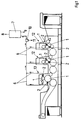
- a rotary printing press known per se is shown with two printing units 12 and a coating unit 13 arranged downstream in the direction of sheet travel.
- Each printing unit 12 has, inter alia, a blanket cylinder and an impression cylinder, which are referred to here as printing press cylinder 1.
- a cleaning device 2 is assigned to each printing press cylinder 1.
- the painting unit 13 has, inter alia, a forme cylinder and an impression cylinder, which are also referred to here as the printing press cylinder 1.
- a cleaning device 2 has a housing 4 which has an opening 15 to the adjacent printing press cylinder 1.
- a cleaning element 3 is arranged in the housing 4, which in the present example is formed by a rotatably mounted, separately driven washing brush. Furthermore, at least one feed for a cleaning fluid, preferably based on vegetable matter and water, a return for contaminated cleaning fluid and a doctor blade (not shown) are arranged in the housing.
- the housing 4 has an approximately rectangular cross section and extends over the full width of the outer surface of the printing press cylinder 1.
- the opening 15 in the housing 4 is dimensioned in a known manner so that the cleaning element 3 is in washing position in the contact position with the outer surface of the printing cylinder 1.
- a gap 14 is present between the housing 4 and the printing press cylinder 1.
- a suction 5 is arranged at the gap 14.
- the suction 5 can be arranged completely or only partially surrounding the opening 15.
- the suction 5 is basically arranged separately from the interior of the housing 4.
- the suction 5 can be guided outside around the housing 4 or integrated into the wall of the housing 4, separated from the interior.
- Suction 5 is followed by a line system 6, which is connected to a liquid separator 10 and a filter 7.
- the filter 7 is coupled to a suction source.
- the liquid separator 10 is connected to the cleaning fluid circuit 11. The cleaning fluid can be reprocessed in the circuit 11.
- the mode of action is as follows:
- the cleaning device 2 is in the parked position with respect to the printing press cylinder 1.
- the cleaning element 3 has no contact with the printing press cylinder 1. If the outer surface of the printing press cylinder 1 is to be washed, the cleaning element 3 is wetted with cleaning fluid in a controlled manner, driven and set against the printing press cylinder. In the case of gripper bridges, the cleaning device 2 is lifted in this area, air from the environment and cleaning fluid (aerosols), cleaning steam, paint residues, paper dust and other dirt residues from the interior of the housing 4 are extracted via the suction 5, line system 6 to the filter 7 via the gap 14 or aspirated liquid separator 10.
- the mixture is separated in the filter 7, so that cleaned air is led to the outside via the exhaust air line 8 and residues can be collected in the residue receptacle 9 and disposed of.
- the line system 6 is interlinked so that each cleaning device in the printing press is connected to the liquid separator 10 and the filter 7 with a corresponding suction source.
- the suction 5 dries the surface of the printing press cylinder 1 at the same time, in which moisture is also sucked off from the outer surface of the printing press cylinder 1.
- the cleaning device 2 is switched off by the printing press cylinder 1. The supply of cleaning fluid and the suction are stopped.
Landscapes
- Inking, Control Or Cleaning Of Printing Machines (AREA)
Abstract
Description
- Die Erfindung betrifft eine Reinigungsvorrichtung für Druckmaschinenzylinder mit mindestens einem in einem Gehäuse aufgenommenen Reinigungselement, wobei das Gehäuse zur Zylindermantelfläche hin eine Öffnung aufweist. Die Erfindung eignet sich insbesondere zur Reinigung von Gummituchzylindern, Gegendruckzylindern sowie Plattenzylindern oder Formzylindern.
- Aus der DE 2 159 115 B2 ist eine Vorrichtung dieser Art zum Reinigen eines Druckmaschinenzylinders bekannt. Die Reinigungsvorrichtung besitzt ein Gehäuse mit einer dem Zylindermantel benachbarten Öffnung. Eine Bürstenwalze dient als Reinigungselement, dem ein Reinigungsfluid zugeführt wird. Weiterhin weist das Gehäuse eine Rücklaufleitung für das verunreinigte Reinigungsfluid auf Das Reinigungsfluid wird beim Waschprozeß vernebelt und der Nebel wird durch die Rücklaufleitung innerhalb des Gehäuses zurückgeführt. Ein Sauggebläse saugt dazu den Reinigungsfluidnebel sowie verbrauchte Reinigungsflüssigkeit und Schmutzteilchen aus dem Gehäuseinneren zurück.
- Nachteilig ist dabei, daß die Absaugung im Gehäuse erfolgt. Dadurch trocknet nicht nur die Waschbürste schneller aus, sondern das verunreinigte Reinigungsfluid, Farbpartikel, Papierstaub etc. werden auch in die Waschbürste gesaugt und von dieser aufgenommen. Bei Verwendung von organischen Lösungsmitteln, z.B. aufBasis von Chlor und Glykol, sind die Waschergebnisse noch befriedigend. Bei der Verwendung von heute gebräuchlichen Reinigungsfluiden auf vegetabiler Basis setzt sich die Waschbürste schnell zu. Dies wirkt sich negativ aufdie Qualität des Waschergebnisses aus und führt zu längeren Waschzeiten.
- Aufgabe der Erfindung ist es, eine Reinigungsvorrichtung zu entwickeln, die das Austreten von Reinigungsfluid bzw. Reinigungsfluiddämpfen, Farbpartikeln sowie Schmutz an der Gehäuseöffnung verhindert ohne das im Gehäuse aufgenommene Reinigungselement zu verunreinigen.
- Erfindungsgemäß wird das durch die Ausbildungsmerkmale des Hauptanspruches gelöst. Weiterbildungen ergeben sich aus den Unteransprüchen.
- Die erfindungsgemäße Reinigungsvorrichtung besteht im wesentlichen aus einem Reinigungselement, das in einem Gehäuse aufgenommen ist. Das Reinigungselement kann dabei ein Reinigungstuch oder eine Waschbürste sein. Das Gehäuse ist zum benachbarten Druckmaschinenzylinder mit einer Öffnung versehen. Die Reinigungsvorrichtung ist an die Mantelfläche des Druckmaschinenzylinders an- und abstellbar und bei Druckmaschinenzylindem mit Greiferbrücken in deren Bereich von der Druckmaschinenmantelfläche abhebbar. Der Öffnung des Gehäuses der Reinigungsvorrichtung ist eine Absaugung zugeordnet. Das Gemisch von Reinigungsfluid, Reinigungsfluiddampf, Farbpartikeln, Schmutz usw. wird am Austreten aus dem Gehäuse gehindert, in dem unmittelbar an der Öffnung die Absaugung erfolgt. Die Absaugung erfolgt dabei in dem Spalt zwischen Gehäuse mit entsprechender Öffnung der Reinigungsvorrichtung und der Zylindermantelfläche. Dabei wird Umgebungsluft und das im Gehäuse vorhandene Gemisch von Reinigungsfluid (Aerosole), Reinigungsdampf; Farbpartikel, Schmutz außerhalb des Gehäuses abgeführt. Dadurch trocknet das Reinigungselement im Gehäuse spürbar weniger aus und gleichzeitig wird eine zusätzliche Verunreinigung des Reinigungselementes vermieden. Durch das Absaugen an der Öffnung des Gehäuses wird gleichzeitig der Trockenprozeß des beim Reinigen verwendeten Reinigungsfluides aufder Zylindermantelfläche beschleunigt. Dies trägt zur Verkürzung der Reinigungszeit bei und der Druckvorgang kann sofort fortgesetzt werden. Durch das Absaugen werden mögliche Aerosole oder Dämpfe des Reinigungsfluides am Austritt in die Umgebung gehindert. Damit wird einer möglichen Verschmutzung der Druckmaschine entgegengewirkt. Weiterhin verbessern sich spürbar die Arbeitsbedingungen, insbesondere der Atemschutz der Bediener. Mögliche Umweltbelastungen werden somit reduziert.
- Die Erfindung soll an einem Ausführungsbeispiel näher erläutert werden. Dabei zeigen:
- Fig. 1
- eine Rotationsdruckmaschine (schematisch),
- Fig. 2
- eine Reinigungsvorrichtung (Seitenansicht).
- Gemäß Fig. 1 ist eine an sich bekannte Rotationsdruckmaschine mit zwei Druckeinheiten 12 und einer in Bogenlaufrichtung nachgeordneten Lackiereinheit 13 dargestellt. Jede Druckeinheit 12 weist unter anderem einen Gummituchzylinder und einen Gegendruckzylinder auf, die hier als Druckmaschinenzylinder 1 bezeichnet sind. Jedem Druckmaschinenzylinder 1 ist eine Reinigungsvorrichtung 2 zugeordnet. Die Lackiereinheit 13 weist unter anderem einen Formzylinder und einen Gegendruckzylinder auf, die hier ebenfalls als Druckmaschinenzylinder 1 bezeichnet sind.
- Gemäß Fig. 2 besitzt eine Reinigungsvorrichtung 2 ein Gehäuse 4, welches zu dem benachbarten Druckmaschinenzylinder 1 hin eine Öffnung 15 aufweist. In dem Gehäuse 4 ist ein Reinigungselement 3 angeordnet, welches im vorliegenden Beispiel durch eine drehbar gelagerte, separat angetriebene Waschbürste gebildet ist. Weiterhin ist in dem Gehäuse mindestens eine Zuführung für ein Reinigungsfluid, vorzugsweise auf vegetabiler Basis und Wasser, eine Rückführung für verunreinigtes Reinigungsfluid sowie eine Rakel angeordnet (nicht gezeigt). Das Gehäuse 4 hat einen annähernd rechteckigen Querschnitt und erstreckt sich über die volle Breite der Mantelfläche des Druckmaschinenzylinders 1. Die Öffnung 15 im Gehäuse 4 ist in bekannter Weise so dimensioniert, daß das Reinigungslement 3 in Anstellposition mit der Mantelfläche des Druckzylinders 1 in Waschkontakt ist. Zwischen Gehäuse 4 und dem Druckmaschinenzylinder 1 ist ein Spalt 14 vorhanden. An der Öffnung 15 des Gehäuses 4 ist am Spalt 14 eine Absaugung 5 angeordnet. Die Absaugung 5 kann dabei die Öffnung 15 vollständig oder auch nur teilweise umschließend angeordnet sein. Die Absaugung 5 ist grundsätzlich vom Innenraum des Gehäuses 4 getrennt angeordnet. Dabei kann die Absaugung 5 außerhalb um das Gehäuse 4 geführt oder in die Wand des Gehäuses 4, vom Innenraum getrennt, integriert sein.
- Der Absaugung 5 ist ein Leitungssystem 6 nachgeordnet, welches mit einem Flüssigkeitsabscheider 10 und einem Filter 7 verbunden ist. Der Filter 7, ein Zyklonfilter, besitzt eine Abluftleitung 8 sowie eine Reststoffauffnahme 9. Der Filter 7 ist mit einer Saugquelle gekoppelt. Der Flüssigkeitsabscheider 10 ist mit dem Reinigungsfluidkreislauf 11 verbunden. Das Reinigungsfluid kann im Kreislauf 11 wieder aufbereitet werden.
- Die Wirkungsweise ist wie folgt:
- Normalerweise befindet sich die Reinigungsvorrichtung 2 in abgestellter Position zum Druckmaschinenzylinder 1. Das Reinigungselement 3 hat keinen Kontakt mit dem Druckmaschinenzylinder 1. Soll die Mantelfläche des Druckmaschinenzylinders 1 gewaschen werden, so wird das Reinigungselement 3 mit Reinigungsfluid gesteuert benetzt, angetrieben und an den Druckmaschinenzylinder angestellt. Bei Greiferbrücken wird die Reinigungsvorrichtung 2 in diesem Bereich ausgehoben, über den Spalt 14 wird Luft aus der Umgebung und Reinigungsfluid (Aerosole), Reinigungsdampf, Farbreste, Papierstaub sowie sonstige Schmutzreste aus dem Inneren des Gehäuses 4 über die Absaugung 5, Leitungssystem 6 zum Filter 7 bzw. Flüssigkeitsabscheider 10 abgesaugt. Im Filter 7 erfolgt die Trennung des Gemisches, so daß gereinigte Luft über die Abluftleitung 8 nach außen geführt wird und Reststoffe in die Reststoffaufnahme 9 aufgefangen und entsorgt werden können. Das Leitungssystem 6 ist untereinander verkettet, so daß jede Reinigungsvorrichtung in der Druckmaschine an den Flüssigkeitsabscheider 10 und den Filter 7 mit entsprechender Saugquelle angeschlossen ist. Die Absaugung 5 trocknet gleichzeitig die Oberfläche des Druckmaschinenzylinders 1, in dem Feuchtigkeit von der Mantelfläche des Druckmaschinenzylinders 1 mit abgesaugt wird. Ist der Reinigungsprozeß beendet, wird die Reinigungsvorrichtung 2 vom Druckmaschinenzylinder 1 abgestellt. Die Zuführung von Reinigungsfluid sowie die Absaugung sind gestoppt.
-
- 1
- Druckmaschinenzylinder
- 2
- Reinigungsvorrichtung
- 3
- Reinigungselement
- 4
- Gehäuse
- 5
- Absaugung
- 6
- Leitungssystem
- 7
- Filter
- 8
- Abluftleitung
- 9
- Reststoffaufnahme
- 10
- Flüssigkeitsabscheider
- 11
- Reinigungsfluidkreislauf
- 12
- Druckeinheit
- 13
- Lackiereinheit
- 14
- Spalt
- 15
- Öffnung
Claims (9)
- Reinigungsvorrichtung für Druckmaschinenzylinder mit einem an- und abstellbaren, geschlossenen Gehäuse mit einer zur Mantelfläche des Druckmaschinenzylinders zugeordneten Öffnung, wobei das Gehäuse mindestens ein im Bereich von Greiferbrükken kontaktfreies Reinigungselement aufnimmt, mindestens eine Zuführung für ein Reinigungsfluid und mindestens eine Abführung für das verunreinigte Reinigungsfluid aufweist,
dadurch gekennzeichnet,
daß die Öffnung (15) eine vom Inneren des Gehäuses (4) getrennte Absaugung (5) aufweist, der mittels einem Leitungssystem (6) ein Filter (7) und ein Flüssigkeitsabscheider (10) nachgeordnet sind. - Reinigungsvorrichtung nach Anspruch 1,
dadurch gekennzeichnet,
daß die Absaugung (5) die Öffnung (15) des Gehäuses (4) vollständig umschließt. - Reinigungsvorrichtung nach Anspruch 1,
dadurch gekennzeichnet,
daß die Absaugung (5) die Öffnung (15) des Gehäuses (4) teilweise umschließt. - Reinigungsvorrichtung nach Anspruch 1,
dadurch gekennzeichnet,
daß die Absaugung (5) außerhalb des Gehäuses (4) angeordnet ist. - Reinigungsvorrichtung nach Anspruch 1,
dadurch gekennzeichnet,
daß die Absaugung (5) in die Wand des Gehäuses (4) integriert ist. - Reinigungsvorrichtung nach Anspruch 1,
dadurch gekennzeichnet,
daß das Reinigungselement (3) ein Waschtuch ist. - Reinigungsvorrichtung nach Anspruch 1,
dadurch gekennzeichnet,
daß das Reinigungselement (3) eine Waschbürste ist. - Reinigungsvorrichtung nach Anspruch 1,
dadurch gekennzeichnet,
daß mehrere Absaugungen (5) mit dem Leitungssystem (6), dem Filter (7) und dem Flüssigkeitsabscheider (10) verkettet sind. - Reinigungsvorrichtung nach Anspruch 1,
dadurch gekennzeichnet,
daß die Absaugung (5) zum Absaugen von Reinigungsfluid (Aerosolen) Reinigungsfluiddämpfen, Farbresten, Schmutz und Papierstaub aus dem Inneren des Gehäuses (4) sowie von Luft aus der Umgebung und zum Trocknen der Mantelfläche des Druckmaschinenzylinders (1) verwendetes wird.
Applications Claiming Priority (2)
| Application Number | Priority Date | Filing Date | Title |
|---|---|---|---|
| DE19520550A DE19520550C2 (de) | 1995-06-06 | 1995-06-06 | Reinigungsvorrichtung für Druckmaschinenzylinder |
| DE19520550 | 1995-06-06 |
Publications (3)
| Publication Number | Publication Date |
|---|---|
| EP0747219A2 true EP0747219A2 (de) | 1996-12-11 |
| EP0747219A3 EP0747219A3 (de) | 1997-05-14 |
| EP0747219B1 EP0747219B1 (de) | 1999-08-11 |
Family
ID=7763693
Family Applications (1)
| Application Number | Title | Priority Date | Filing Date |
|---|---|---|---|
| EP96108691A Expired - Lifetime EP0747219B1 (de) | 1995-06-06 | 1996-05-31 | Reinigungsvorrichtung für Druckmaschinenzylinder |
Country Status (3)
| Country | Link |
|---|---|
| EP (1) | EP0747219B1 (de) |
| AT (1) | ATE183138T1 (de) |
| DE (2) | DE19520550C2 (de) |
Cited By (6)
| Publication number | Priority date | Publication date | Assignee | Title |
|---|---|---|---|---|
| EP0928687A1 (de) * | 1997-12-16 | 1999-07-14 | Richard Munz | Gummituchreinigungsvorrichtung in einer Druckmaschine |
| AT407134B (de) * | 1999-04-28 | 2000-12-27 | Manfred Anfang | Reinigungsgerät für gegendruckzylinder von flexo- oder tiefdruckmaschinen |
| WO2002036346A1 (en) * | 2000-11-06 | 2002-05-10 | Dynamic Products Limited | In-line cleaning and recycling of media deposits from an impression cylinder in a tissue printing machine |
| EP1486330A3 (de) * | 2003-06-12 | 2006-05-24 | Baldwin-Japan Ltd. | Vorrichtung zum Reinigen eines Zylinders |
| FR2930768A1 (fr) * | 2008-04-30 | 2009-11-06 | Goss Int Montataire Sa | Dispositif d'acheminement d'un substrat plat a dispositif de nettoyage, dispositif de coupe, presse d'impression et utilisation correspondants |
| EP1981655B2 (de) † | 2005-12-27 | 2017-12-13 | manroland sheetfed GmbH | Reinigungseinrichtung an einer prägevorrichtung |
Families Citing this family (7)
| Publication number | Priority date | Publication date | Assignee | Title |
|---|---|---|---|---|
| DE29620271U1 (de) * | 1996-11-21 | 1997-01-09 | MAN Roland Druckmaschinen AG, 63075 Offenbach | Reinigungsvorrichtung für einen Zylinder einer Druckmaschine |
| DE10027023B4 (de) * | 2000-05-31 | 2004-07-29 | Koenig & Bauer Ag | Vorrichtungen zur Reinigung einer Walze oder eines Zylinders |
| DE10027021B4 (de) * | 2000-05-31 | 2004-04-08 | Koenig & Bauer Ag | Vorrichtung zur Reinigung einer Walze oder eines Zylinders |
| DE10027022B4 (de) * | 2000-05-31 | 2004-07-29 | Koenig & Bauer Ag | Vorrichtung zur Reinigung einer Walze oder eines Zylinders |
| DE202008018136U1 (de) | 2008-07-10 | 2011-12-30 | Manroland Ag | Rollenrotationsdruckmaschine mit Entstaubungsvorrichtung für eine Papierbahn |
| DE102008032421A1 (de) | 2008-07-10 | 2010-01-14 | Manroland Ag | Rollenrotationsdruckmaschine mit Entstaubungsvorrichtung für eine Papierbahn |
| DE102011012891A1 (de) * | 2010-03-29 | 2011-09-29 | Heidelberger Druckmaschinen Ag | Rotationsdruckwerk mit einem Druckformzylinder und einem Übertragungszylinder |
Family Cites Families (12)
| Publication number | Priority date | Publication date | Assignee | Title |
|---|---|---|---|---|
| DE523356C (de) * | 1929-05-24 | 1931-04-22 | Marius Ratignier | Verfahren zum Bedrucken von Geweben auf Mehrfarbendruckmaschinen |
| DD34030A1 (de) * | 1962-11-20 | 1964-12-05 | Georg Krause | Gerät zum Reinigen von Druckzylindern an Druckmaschinen |
| US3835779A (en) * | 1973-01-26 | 1974-09-17 | Pitney Bowes Inc | Apparatus for automatically cleaning the blanket cylinder of an offset printer |
| DE2815388C3 (de) * | 1978-04-10 | 1981-06-11 | M.A.N.- Roland Druckmaschinen AG, 6050 Offenbach | Vorrichtung zum Waschen von Zylindern an Druckmaschinen, insbesondere Offsetdruckmaschinen |
| DE3025639A1 (de) * | 1980-07-07 | 1982-01-21 | Maschinenfabrik Goebel Gmbh, 6100 Darmstadt | Einrichtung zum reinigen eines an einer stahlstichdruckmaschine befindlichen wischzylinders |
| DE3614496A1 (de) * | 1986-04-29 | 1987-11-05 | Heidelberger Druckmasch Ag | Waschvorrichtung fuer druckzylinder von druckmaschinen |
| JPH07103519B2 (ja) * | 1988-09-22 | 1995-11-08 | 富士写真フイルム株式会社 | ロール表面クリーニング装置 |
| DE4203914A1 (de) * | 1991-02-12 | 1992-09-10 | Jpe Kk | Vorrichtung zum reinigen eines druckzylinders in einer druckmaschine |
| DE4116762A1 (de) * | 1991-05-23 | 1992-11-26 | Roland Man Druckmasch | Vorrichtung zum waschen eines zylinders einr druckmaschine |
| DE9115948U1 (de) * | 1991-12-21 | 1992-02-20 | Lößner, Wolfgang, 6229 Kiedrich | Waschanlage für den Gummituchzylinder einer Offsetdruckmaschine |
| SE500772C2 (sv) * | 1992-11-25 | 1994-08-29 | Staffan Sjoeberg | Anordning för rengöring av föremål i rörelse |
| DE4335097C2 (de) * | 1993-10-14 | 1999-02-25 | Baldwin Grafotec Gmbh | Vorrichtung zum Temperieren von Druckmaschinenzylindern und -walzen |
-
1995
- 1995-06-06 DE DE19520550A patent/DE19520550C2/de not_active Expired - Fee Related
-
1996
- 1996-05-31 DE DE59602697T patent/DE59602697D1/de not_active Expired - Fee Related
- 1996-05-31 EP EP96108691A patent/EP0747219B1/de not_active Expired - Lifetime
- 1996-05-31 AT AT96108691T patent/ATE183138T1/de not_active IP Right Cessation
Cited By (10)
| Publication number | Priority date | Publication date | Assignee | Title |
|---|---|---|---|---|
| EP0928687A1 (de) * | 1997-12-16 | 1999-07-14 | Richard Munz | Gummituchreinigungsvorrichtung in einer Druckmaschine |
| AT407134B (de) * | 1999-04-28 | 2000-12-27 | Manfred Anfang | Reinigungsgerät für gegendruckzylinder von flexo- oder tiefdruckmaschinen |
| WO2002036346A1 (en) * | 2000-11-06 | 2002-05-10 | Dynamic Products Limited | In-line cleaning and recycling of media deposits from an impression cylinder in a tissue printing machine |
| GB2387814A (en) * | 2000-11-06 | 2003-10-29 | Dynamic Products Ltd | In-line cleaning and recycling of media deposits from an impression cylinder in a tissue printing machine |
| EP1486330A3 (de) * | 2003-06-12 | 2006-05-24 | Baldwin-Japan Ltd. | Vorrichtung zum Reinigen eines Zylinders |
| US7219605B2 (en) | 2003-06-12 | 2007-05-22 | Baldwin-Japan, Ltd. | Cylinder cleaning apparatus |
| EP1981655B2 (de) † | 2005-12-27 | 2017-12-13 | manroland sheetfed GmbH | Reinigungseinrichtung an einer prägevorrichtung |
| FR2930768A1 (fr) * | 2008-04-30 | 2009-11-06 | Goss Int Montataire Sa | Dispositif d'acheminement d'un substrat plat a dispositif de nettoyage, dispositif de coupe, presse d'impression et utilisation correspondants |
| WO2009138693A3 (fr) * | 2008-04-30 | 2010-01-07 | Goss International Montataire Sa7 | Dispositif d'acheminement d'un substrat plat à dispositif de nettoyage, dispositif de coupe, presse d'impression et utilisation correspondants |
| CN102083724A (zh) * | 2008-04-30 | 2011-06-01 | 戈斯国际蒙塔泰尔公司 | 包括清洁设备的扁平基材输送设备、相应的切割设备、印刷机和所述设备的使用方法 |
Also Published As
| Publication number | Publication date |
|---|---|
| EP0747219B1 (de) | 1999-08-11 |
| ATE183138T1 (de) | 1999-08-15 |
| EP0747219A3 (de) | 1997-05-14 |
| DE19520550A1 (de) | 1996-12-12 |
| DE19520550C2 (de) | 1999-03-25 |
| DE59602697D1 (de) | 1999-09-16 |
Similar Documents
| Publication | Publication Date | Title |
|---|---|---|
| EP0747217B1 (de) | Verfahren und Vorrichtung zum Reinigen eines Zylinders einer Rotations-Druckmaschine | |
| EP0747219B1 (de) | Reinigungsvorrichtung für Druckmaschinenzylinder | |
| DE2815388B2 (de) | Vorrichtung zum Waschen von Zylindern an Druckmaschinen, insbesondere Offsetdruckmaschinen | |
| DE19600846C1 (de) | Vorrichtung zur Reinigung direkt bebilderter Druckformen in einer Druckmaschine | |
| EP0659560B1 (de) | Reinigungseinrichtung für Zylinder von Druckmaschinen, vorzugsweise Offsetdruckmaschinen | |
| EP1004436B1 (de) | Sprühfeuchtwerk | |
| DE102008002048B4 (de) | Verwendung einer Reinigungsanlagen zum Reinigen einer oder mehrere Druckwerkszylinder einer Druckeinheit einer Druckmaschine | |
| DE3042619C2 (de) | Vorrichtung zur Kanal- und Grubenreinigung | |
| DE19614395C2 (de) | Verfahren und Vorrichtung zum Reinigen eines Druckmaschinenzylinders und/oder von Walzen | |
| EP0606581B1 (de) | Vorrichtung zum automatischen Reinigen von Gummituchzylindern in einer Offsetdruckmaschine | |
| DE19734103A1 (de) | Einrichtung zum Entwickeln von zylindrischen Oberflächen | |
| DE19648193C2 (de) | Waschvorrichtung zum Reinigen eines Zylinders einer Druckmaschine | |
| DE2166719A1 (de) | Reinigungsvorrichtung fuer drucktuchzylinder einer offsetdruckmaschine | |
| EP1981655B2 (de) | Reinigungseinrichtung an einer prägevorrichtung | |
| EP0698489A2 (de) | Vorrichtung zum Entsorgen von Farbe oder Lack aus Behältern mit einer zugeordneten Walze in einer Rotationsdruckmaschine | |
| DE631858C (de) | Vorrichtung zum Auffangen und Sammeln von Papierstaub und anderen beim Schneiden von Papierbahnen entstehenden Abfaellen | |
| DE19816654B4 (de) | Einrichtung zum Bebildern zylindrischer Oberflächen in Druckmaschinen | |
| EP0711666A2 (de) | Reinigungseinrichtung für eine Bogenleiteinrichtung einer Rotationsdruckmaschine | |
| EP0771650B1 (de) | Bogenrotationsdruckmaschine | |
| EP0770483B1 (de) | Waschvorrichtung zur Reinigung von Zylindern eines Offsetdruckwerkes | |
| EP1211071B1 (de) | Sprühvorrichtung für eine Druckmaschine | |
| EP0378180B1 (de) | Verfahren und Vorrichtung zum Reinigen von Gummituchzylindern einer Rollenrotationsdruckmaschine | |
| EP1060888B1 (de) | Reinigungsvorrichtung für die graphische Industrie | |
| DE10063033A1 (de) | Puderabsaugeinrichtung an Druckmaschinen | |
| DE20021816U1 (de) | Puderabsaugeinrichtung an Druckmaschinen |
Legal Events
| Date | Code | Title | Description |
|---|---|---|---|
| PUAI | Public reference made under article 153(3) epc to a published international application that has entered the european phase |
Free format text: ORIGINAL CODE: 0009012 |
|
| 17P | Request for examination filed |
Effective date: 19960625 |
|
| AK | Designated contracting states |
Kind code of ref document: A2 Designated state(s): AT CH DE FR GB IT LI NL |
|
| PUAL | Search report despatched |
Free format text: ORIGINAL CODE: 0009013 |
|
| AK | Designated contracting states |
Kind code of ref document: A3 Designated state(s): AT CH DE FR GB IT LI NL |
|
| 17Q | First examination report despatched |
Effective date: 19980305 |
|
| GRAG | Despatch of communication of intention to grant |
Free format text: ORIGINAL CODE: EPIDOS AGRA |
|
| GRAG | Despatch of communication of intention to grant |
Free format text: ORIGINAL CODE: EPIDOS AGRA |
|
| GRAH | Despatch of communication of intention to grant a patent |
Free format text: ORIGINAL CODE: EPIDOS IGRA |
|
| GRAH | Despatch of communication of intention to grant a patent |
Free format text: ORIGINAL CODE: EPIDOS IGRA |
|
| ITF | It: translation for a ep patent filed | ||
| GRAA | (expected) grant |
Free format text: ORIGINAL CODE: 0009210 |
|
| AK | Designated contracting states |
Kind code of ref document: B1 Designated state(s): AT CH DE FR GB IT LI NL |
|
| REF | Corresponds to: |
Ref document number: 183138 Country of ref document: AT Date of ref document: 19990815 Kind code of ref document: T |
|
| REG | Reference to a national code |
Ref country code: CH Ref legal event code: NV Representative=s name: E. BLUM & CO. PATENTANWAELTE Ref country code: CH Ref legal event code: EP |
|
| ET | Fr: translation filed | ||
| GBT | Gb: translation of ep patent filed (gb section 77(6)(a)/1977) |
Effective date: 19990812 |
|
| REF | Corresponds to: |
Ref document number: 59602697 Country of ref document: DE Date of ref document: 19990916 |
|
| PLBE | No opposition filed within time limit |
Free format text: ORIGINAL CODE: 0009261 |
|
| STAA | Information on the status of an ep patent application or granted ep patent |
Free format text: STATUS: NO OPPOSITION FILED WITHIN TIME LIMIT |
|
| 26N | No opposition filed | ||
| REG | Reference to a national code |
Ref country code: GB Ref legal event code: IF02 |
|
| PGFP | Annual fee paid to national office [announced via postgrant information from national office to epo] |
Ref country code: CH Payment date: 20020416 Year of fee payment: 7 |
|
| PGFP | Annual fee paid to national office [announced via postgrant information from national office to epo] |
Ref country code: NL Payment date: 20020430 Year of fee payment: 7 |
|
| PGFP | Annual fee paid to national office [announced via postgrant information from national office to epo] |
Ref country code: GB Payment date: 20020502 Year of fee payment: 7 Ref country code: AT Payment date: 20020502 Year of fee payment: 7 |
|
| PGFP | Annual fee paid to national office [announced via postgrant information from national office to epo] |
Ref country code: FR Payment date: 20020513 Year of fee payment: 7 |
|
| PG25 | Lapsed in a contracting state [announced via postgrant information from national office to epo] |
Ref country code: LI Free format text: LAPSE BECAUSE OF NON-PAYMENT OF DUE FEES Effective date: 20030531 Ref country code: GB Free format text: LAPSE BECAUSE OF NON-PAYMENT OF DUE FEES Effective date: 20030531 Ref country code: CH Free format text: LAPSE BECAUSE OF NON-PAYMENT OF DUE FEES Effective date: 20030531 Ref country code: AT Free format text: LAPSE BECAUSE OF NON-PAYMENT OF DUE FEES Effective date: 20030531 |
|
| PG25 | Lapsed in a contracting state [announced via postgrant information from national office to epo] |
Ref country code: NL Free format text: LAPSE BECAUSE OF NON-PAYMENT OF DUE FEES Effective date: 20031201 |
|
| REG | Reference to a national code |
Ref country code: CH Ref legal event code: PL |
|
| GBPC | Gb: european patent ceased through non-payment of renewal fee |
Effective date: 20030531 |
|
| PG25 | Lapsed in a contracting state [announced via postgrant information from national office to epo] |
Ref country code: FR Free format text: LAPSE BECAUSE OF NON-PAYMENT OF DUE FEES Effective date: 20040130 |
|
| NLV4 | Nl: lapsed or anulled due to non-payment of the annual fee |
Effective date: 20031201 |
|
| REG | Reference to a national code |
Ref country code: FR Ref legal event code: ST |
|
| PGFP | Annual fee paid to national office [announced via postgrant information from national office to epo] |
Ref country code: IT Payment date: 20060531 Year of fee payment: 11 |
|
| PGFP | Annual fee paid to national office [announced via postgrant information from national office to epo] |
Ref country code: DE Payment date: 20080523 Year of fee payment: 13 |
|
| PG25 | Lapsed in a contracting state [announced via postgrant information from national office to epo] |
Ref country code: IT Free format text: LAPSE BECAUSE OF NON-PAYMENT OF DUE FEES Effective date: 20070531 |
|
| PG25 | Lapsed in a contracting state [announced via postgrant information from national office to epo] |
Ref country code: DE Free format text: LAPSE BECAUSE OF NON-PAYMENT OF DUE FEES Effective date: 20091201 |